investigation on the impacts of traffic...
TRANSCRIPT

INVESTIGATION ON THE IMPACTS OF TRAFFIC ENERGY
HARVESTER ON SPEED BREAKERS
MARK LAU KIEW TUNG
A project report submitted in partial fulfilment of the
requirements for the award of Bachelor of Engineering
(Hons.) Electrical and Electronic Engineering
Lee Kong Chian Faculty of Engineering and Science
Universiti Tunku Abdul Rahman
May 2016

ii
DECLARATION
I hereby declare that this project report is based on my original work except for
citations and quotations which have been duly acknowledged. I also declare that it
has not been previously and concurrently submitted for any other degree or award at
UTAR or other institutions.
Signature :
Name :
ID No. :
Date :

iii
APPROVAL FOR SUBMISSION
I certify that this project report entitled “INVESTIGATION ON THE IMPACTS
OF TRAFFIC ENERGY HARVESTER ON SPEED BREAKERS” prepared by
MARK LAU KIEW TUNG has met the required standard for submission in partial
fulfilment of the requirements for the award of Bachelor of Engineering (Hons.)
Electrical and Electronic Engineering at Universiti Tunku Abdul Rahman.
Approved by,
Signature :
Supervisor :
Date :

iv
The copyright of this report belongs to the author under the terms of the
copyright Act 1987 as qualified by Intellectual Property Policy of Universiti Tunku
Abdul Rahman. Due acknowledgement shall always be made of the use of any
material contained in, or derived from, this report.
© 2016, MARK LAU KIEW TUNG. All right reserved.

v
Specially dedicated to
my beloved mother and father

vi
ACKNOWLEDGEMENTS
I would like to thank everyone who had contributed to the successful completion of
this project. I would like to express my gratitude to my research supervisor, Dr.
Stella Morris for her invaluable advice, guidance and her enormous patience
throughout the development of the research.
In addition, I would also like to express my gratitude to my loving parents
and friends who had helped and given me encouragement throughout the process.
vii
INVESTIGATION ON THE IMPACTS OF TRAFFIC ENERGY
HARVESTER ON SPEED BREAKERS
ABSTRACT
In recent years, over-dependency on non-renewable resources as power source has
caused energy crisis. As the human population is increasing day by day and the non-
renewable resources are diminishing, there is need for a solution to tackle this issue.
Thus, various traffic energy harvesters had been proposed in many researches.
However, these devices to harvest the traffic energy have low implementation across
the country. This is due to the poor understanding and doubts on the implementation
of these devices such as the possible impacts to the society. Thus, this project is
carried out to study these impacts of traffic energy harvester on speed breakers and to
clear those doubts. In this project, the speed breaker is utilized to generate electricity
from the traffic energy as the vehicles travel across it. Traffic energy can be
considered as renewable energy as it is available all year round but it will be wasted
if it is left untapped. The rack and pinion mechanism is chosen to tap this energy and
convert it to useful energy. The potential energy from the vehicle as it passes through
the bump is converted into kinetic energy by this mechanism which is then used to
rotate the rotor of generator and electricity is produced. The issue on the suitability of
the mechanism to be implemented is discussed in this report.

viii
TABLE OF CONTENTS
DECLARATION ii
APPROVAL FOR SUBMISSION iii
ACKNOWLEDGEMENTS vi
ABSTRACT vii
TABLE OF CONTENTS viii
LIST OF TABLES xii
LIST OF FIGURES xii
CHAPTER
1 INTRODUCTION 133
1.1 Background 133
1.2 Advantages 134
1.3 Problem Statement 15
1.4 Aim and Objectives 15
1.5 Topic Outline 16
2 LITERATURE REVIEW 18
2.1 Traffic Energy Harvesting 18
2.2 Electricity Generation through Speed Breaker 19
2.2.1 Rack and Pinion Mechanism 19
2.2.2 Roller Mechanism 21
2.2.3 Crankshaft Mechanism 22
2.2.4 Comparison between Different Mechanisms 22
2.3 Durability of Speed Breaker Mechanism 23

ix
2.3.1 Components in Rack and Pinion Mechanism 23
2.3.1.1 Rack and Pinion 24
2.3.1.2 Springs 24
2.3.1.3 Spur Gears 24
2.3.1.4 Flywheel 24
2.3.1.5 Shaft 25
2.3.1.6 Generator 25
2.3.2 Von Mises Stress 25
2.4 Impact of Speed Breaker on Its Surrounding 26
2.4.1 Damage to the Road and Speed Breaker
by Heavy Vehicles 26
2.4.2 Fuel Use and Vehicle Operating Costs 26
2.4.3 Emissions 27
2.4.4 Energy Efficiency 27
2.5 Conclusion 28
3 METHODOLOGY 29
3.1 Overview 29
3.2 Literature Review 30
3.3 Concept design of the speed breaker mechanism 30
3.4 Modeling of mechanical components of the speed breaker
mechanism 32
3.4.1 Helical Spring Design 32
3.4.2 Rack and Pinion 34
3.4.3 Design of Gears 34
3.5 Development of model of a conventional speed breaker 35
3.6 Development of model of a speed breaker with energy
harvester 35
3.7 Simulation of the material and numerical parameters, such as
tensile strength, stresses and strain forces on the response of
the speed breakers 36
3.8 Documentation 37
3.9 Conclusion 38

x
4 RESULTS AND DISCUSSION 39
4.1 Introduction 39
4.2 Modelling 39
4.3 Working Principle 41
4.4 Constructional Material(s) 41
4.5 Stress Analysis 44
4.5.1 Von Mises Stress and Strain 46
4.5.2 Displacement 48
4.5.3 Safety Factor 49
4.5 Conclusion 49
5 CONCLUSION AND RECOMMENDATIONS 51
5.1 Conclusion 51
5.2 Recommendations 52
5.3 Applications 53
REFERENCES 54

xi
LIST OF TABLES
TABLE TITLE PAGE
3.1 Gantt Chart for the whole project 30
3.2 Material for each component 37
4.1 Properties of concrete 42
4.2 Properties of Steel 42
4.3 Properties of stainless steel 43
4.4 A force of 20000N which is the average weight of
a car is applied on the selected faces 44
4.5 Summary of results for speed breaker with energy
harvester 45
4.6 Summary of results for conventional speed breaker 46

xii
LIST OF FIGURES
FIGURE TITLE PAGE
2.1 Rack and Pinion Gear Arrangement 20
2.2 Rack and Pinion Model 20
2.3 Roller Mechanism Model 21
2.4 Crankshaft 22
2.5 Six stress components of 3D 25
3.1 Schematic diagram of helical spring under load 32
4.1 Components of speed breaker with energy
harvester 40
4.2 Simulation model 41
4.3 Selected face(s) subjected to forces 44
4.4 selected face(s) subjected to constraints 45
4.5 Von Mises Stress 47
4.6 Strain 48
4.7 Displacement 49
4.8 Safety Factor 50

13
CHAPTER 1
1 INTRODUCTION
1.1 Background
In this modern era, our natural resources such as water, food, wood, natural gas, oil,
and so on are slowly diminishing from our planet as we do not take the necessary
counter measures to protect and prevent it from vanishing. Natural resources are
essential for the survival of human kinds. They are the main sources of our daily
needs. However, due to extensive usage of energy, these vast natural resources are
being exploited to satisfy our needs which cause energy crisis. Thus, methods of
optimal utilization are necessary in order to overcome the crisis and to conserve these
natural resources. One of the best possible solutions is to reduce the dependencies on
non-renewable resources like fossil fuels. Much of the industries are still powered by
fossil fuels, but new technologies are evolving as the time goes on with the use of
renewable energies such as solar, wind, water and so on. However, this isn’t easy as
many leading industries still uses fossil fuels as their primary power source for
manufacturing.
Energy exists in many different forms such as light energy, heat energy,
electrical energy, mechanical energy, nuclear energy and so on. One among these
energies is traffic energy. Rather than being left untapped and wasted as heat energy,
harvesting it would make a tremendous deal in combating the over-dependency on
non-renewable energy, as traffic energy can be considered as a renewable energy.
These forms of energy can be transferred and converted between one another. Energy
can be divided into two major types which are potential energy and kinetic energy.

14
This project utilizes both the potential and kinetic energy through a commonly used
system, the speed breaker. Energy tapped from this mechanism can be used to power
up nearby electrical appliances such as street lamps. Among many proposed methods
to implement this mechanism, the common methods used are rack and pinion
mechanism, roller mechanism and crankshaft mechanism. When the load of the
vehicles exerts force upon the speed breaker, the potential energy is converted into
kinetic energy through various mechanisms where the motion is transferred into a
generator to generate electricity.
1.2 Advantages
Traffic energy harvesting does not require consumption of fossil fuel as its source of
power (potential energy from the vehicles when travel across the speed breaker) can
be considered as a renewable energy. Thus, it is environmentally friendly. With zero
consumption on fossil fuels, it helps in conserving the natural resources. In this
mechanism, the source of power from the potential energy produced by vehicles on
the bumper as it comes to a halt is converted to kinetic energy and then electrical
energy by the mechanism in the speed breaker. This energy if left untapped will be
wasted in the form of heat. Since this energy relies only on the vehicles and the
mechanism itself, the energy is available all year round with no shortage of energy
source.
Besides, this mechanism also has zero emission of greenhouse gases such as
carbon dioxide, nitrogen oxide methane and other gases which are harmful to our
environment because it mainly depends on the mechanical energy. Thus, it helps in
combating against the global warming that results in climate change, rising of water
levels and other natural impacts.

15
1.3 Problem Statements
Currently, the most advanced and efficient methods of power generation are from
carbon related sources extracted from fossil fuels. In Malaysia, the
existing power network is mostly operated on diesel and coals. Thus, an alternative
source of power is needed to provide solution on the over-dependency of non-
renewable resources which can harm our environment. A need of clean and
environmentally friendly sources is vital in combating against the carbon related
environmental impacts such as global
warming. A combination of renewable energy and energy harvesting would provide
a viable solution. Harvesting the energy from vehicles through speed breakers would
contribute to the Malaysia’s target of becoming carbon neutral.
However, there are doubts in our society on the practical implementation of
traffic energy harvester. This is the main reason of the low implementation of traffic
energy harvester devices across the world. Among many traffic energy harvester
devices that have been proposed, this project emphasizes on the speed breaker as the
mechanism to harvest the traffic energy. In order to implement the speed breaker as a
power generation unit, impact study on this new mechanism is important. It is
important to prove that it is has the potential to be developed in large scale, and
prove its practicability and cost effectiveness in comparison to conventional speed
breaker in order to clear the doubts on its effectiveness as a power generation unit.
Thus, this project is to investigate the impacts of traffic energy harnessing system on
speed breakers to determine its positive and negative impacts on our society.
Through this project, the possible impacts on the power generation speed breaker are
being researched. Based on these impacts, simulations on speed breaker mechanism
are being conducted to show the effects of these impacts on real life situation.

16
1.4 Aims and Objectives
The aim of this project is to investigate the impacts of the traffic energy harvester on
speed breakers. The impact study of the speed breaker power generation on the road
and speed breaker itself is very critical in combating against the over-dependence of
power generation from non-renewable resources. The objectives of this study are as
follows:
1. To identify the possible impacts of the traffic energy harnessing system on
speed breakers.
2. To identify a suitable design for the speed breaker and the harnessing
mechanism.
3. To simulate the speed breaker and the harnessing mechanism using Autodesk
Inventor.
4. To investigate the effect of material and numerical parameters, such as tensile
strength, stresses and strain forces on the durability of the speed breaker.
1.5 Topic Outline
In this topic of Investigation on the Impacts of Traffic Energy Harvester on Speed
Breakers, a speed breaker is used as an energy harvester mechanism. It uses the
traffic energy as source of energy which is a renewable energy. The traffic energy is
mainly comprises of mechanical energy which is potential energy and kinetic energy.
However, there are doubts in our society on the practical implementation of traffic
energy harvester. Therefore, the aim of this project is to investigate the impacts of
the traffic energy harvester on speed breakers to prove its practicability in
comparison to conventional speed breaker.
There are lots of researches being done on the design of energy harvesters for
the speed breaker. However, there are none investigate on impacts of these traffic
energy harvester on the speed breaker. Few mechanisms have been proposed as
energy harvester for the speed breaker such as rack and pinion mechanism,

17
crankshaft mechanism and roller mechanism. The literature review in this paper
shows the comparison between these mechanisms. Among these mechanisms, rack
and pinion mechanism is considered to be the best. The rack and pinion mechanism
consists of mechanical components such as rack and pinion, gears, chain drives and
others. There is also review on the possible impacts of the speed breaker with energy
harvester on its surrounding.
For methodology part, firstly, the concept design for the speed breaker is
being drafted based on the design of other researches in this mechanism. Then based
on the design, the mechanical components of the speed breaker mechanism are being
modelled. After the development of the mechanical components, they are integrated
into a simulation model. A model of conventional speed breaker is also being
modelled to make a comparison. Then, the models are simulated based on the
material and numerical parameters on the response of the speed breakers.
As for results and discussions, the working principle of the design of rack and
pinion is being determined based on the simulation of the models. Each of the
components is being assigned with materials which have its own properties of yield
and tensile strength. Then, stress analysis is used to simulate and analysed the models.
From the results, suitability of the design of the rack and pinion mechanism to
be implemented is being determined. There are improvements and changes that can
be done on the mechanism to improve its design. This mechanism has a great
potential as it has many applications such as to power the traffic lights and street
lights.
18
CHAPTER 2
2 LITERATURE REVIEW
2.1 Traffic Energy Harvesting
Energy harvesting is the process where the energy is harnessed from other sources
like traffic energy which is unused and depleted, which is then converted to a more
usable form. Energy harvesters provide power for low energy electronics in a very
small amount. The source of energy for the energy harvesters is free without
depleting the natural resources.
There are some researches on the traffic energy harvesting in the pavement
engineering field. Andriopoulou (2012) had discussed on the technologies for traffic
energy harvesting that have been studied such as asphalt solar collector combined
with piping system, photovoltaic applications in the road infrastructure, embedded
piezoelectric sensors and so on. For asphalt solar collector, the solar energy are being
extracted and converted into thermal or electrical energy. The warmth of the asphalt
pavement is captured by the water piping system and the energy is stored. As for the
PV system, it is embedded into the pavement infrastructure. It captures the solar
energy and converts it into electrical energy which is then being stored. Then, for the
embedded piezoelectric sensors in the pavement infrastructure, it generates electrical
voltage due to the alteration to its dimension when there are mechanical stresses.
However, in this paper, traffic harvesting through speed breaker is being
introduced and studied. This is because this mechanism has a high energy efficiency
and cost effective to be implemented.

19
2.2 Electricity Generation through Speed Breaker
There are different types of mechanism developed for generation of electricity from
speed breaker. Among these, the popular ones are Rack and Pinion, Roller and
Crankshaft mechanism. For Rack and Pinion and Crankshaft mechanism, basically,
it involves weight from vehicles that exerted a force upon the speed breaker. The
potential energy from the compression of the dome of the speed breaker is converted
into kinetic energy through these mechanisms where the motion is transfer into a
generator to generate electricity. In Roller mechanism, the friction force due to the
vehicle movement acted upon the roller is then transmitted to chain sprocket
arrangements where the rotary motion is then transfer into a generator for electricity
generation.
2.2.1 Rack and Pinion Mechanism
Rack and pinion is used to convert between rotary and linear motion. Flat toothed
part is the rack, while gear is the pinion. Whenever a car is travelled across the speed
breaker, the dome is pressed downwards. The rack attached to the bottom of the
dome will move downward which will rotates the pinion. Through multiple series of
gear drives, the speed of the rotation of gear is multiplied to higher speed that is
enough to power the generator. The electricity produced from the generator will be
stored in a battery which will be used to power the street lamps.
In Aniket, Pratik and Atul (2013), rack and pinion mechanism is used to
harness traffic energy. Through calculation, it is found that when a 300kg vehicle
travelled over the speed breaker, a power of 7.3575W is generated for every second
which is 10.5948kW of power for 24 hours. This power output is more than
sufficient to power four street lamps during the night.
Similar mechanism of rack and pinion was used in Aswathaman and
Priyadharshini (2011). Through their experiment investigation, it is found that a
vehicle travelling over the speed breaker at different speeds and loads, will generate

20
different voltages. As the speed of the vehicle increases at constant load, the voltage
generated from the mechanism decreases. However, when the load of the vehicle
increases which travelled at a constant speed across the speed breaker, the voltage
generated by the mechanism increases.
Aravind, et al. (2015) makes some modifications to the conventional design
of rack and pinion mechanism with shortened rack and removal of spur gears. It
reduces the number of moving parts thus increasing the power generation and
reducing the cost of investments.
Figure 2.1: (Padma, Kiran, Suresh, 2014. p. 550) Rack and Pinion Gear
Arrangement
Figure 2.2: (Aniket, Pratik and Atul, 2013. p. 26) Rack and Pinion Model

21
2.2.2 Roller Mechanism
In this mechanism, rollers are fitted in between the speed breaker. The friction force
due to the vehicle movement across the speed breaker acted upon the rollers and
rotates them. With the help of chain drive, the rotation of the rollers will rotate the
shaft of the generator. As the shaft of the generator rotates, electricity is produced.
Santhosh, Jyothi and Sudhir (2014) used roller mechanism for speed breaker
power generation. In their investigation, it is found that the vehicle speed is inversely
proportional to the voltage and current generated when the load of the vehicle is kept
constant. However, the load of vehicle is directly proportional to the voltage and
current generated when the speed of the vehicle travelling across the speed breaker is
kept constant. Through calculation, it is found that the roller mechanism can generate
a power of 1.67 W in a minute which is 2.3kW in 24 hours with a mass of vehicle of
205kg travelling across the speed breaker.
In Piyush, et al. (2014) has proposed model of the roller mechanism using
Solidworks and analysed using ANSYS. The model was set up and experimented by
a two-wheeler vehicle travelling across the model at different speeds to get the
reading of voltage and current generated under different conditions. It can be seen
that moving a small vehicle over the roller with its speed varies from 10-15 km/hour;
the voltage produced is in the range of 3-4V.
Figure 2.3: (Piyush, et al., 2014. p. 591) Roller Mechanism Model

22
2.2.3 Crankshaft Mechanism
The working principles of crankshaft mechanism is basically similar to that of rack
and pinion mechanism which instead of using rack and pinion as its mechanical parts,
it uses crankshaft. The linear motion of the dome of speed-breaker due to the
compression of car is converted into rotary motion by the crankshaft. The crankshaft
is then coupled with a larger gear. The large gear is meshed directly to a smaller gear
which transmits the power of the larger gear to a smaller pinion. The speed at the
larger gear is multiplied as the power is being transmitted to the smaller pinion. As
the power is being transmitted to the gear drives, the speed is multiplied to a higher
speed which is enough to turn the rotor of a generator to generate electricity.
Figure 2.4: Crankshaft
Venkata, et al. (2014) calculated approximately 3.5MW of power output
generated in 24 hours for its design of crankshaft mechanism.
2.2.4 Comparison between Different Mechanisms
Since there are a few mechanisms that are being proposed to be implemented in the
speed breaker, comparison is being made to determine the most desirable mechanism.
Zeeshan, Muhammad and Abubakr (2014) had made comparison between the three
mechanisms which are rack and pinion mechanism, roller mechanism and crankshaft
mechanism. Roller mechanism has a few disadvantages which are the difficulty in
maintenance and might cause collision. For crankshaft mechanism, there are also a
few disadvantages which are mechanical vibration that may cause damage to the
bearings, the requirement of crankshaft to be mounted on bearings which can cause

23
balancing problems, and variation of loads that also leads to balancing problem as
bearings are of sliding type. As for rack and pinion mechanism, the paper had stated
that it has a few advantages which it gives good mounting convenience, small
maximum gear losses of 3 to 5% and high efficiency approximate to 95%. Thus, rack
and pinion mechanism is found to be the most suitable to be implemented in the
speed breaker to provide a more desirable output.
2.3 Durability of Speed Breaker Mechanism
With a new mechanism integrated in the speed breaker, it is of much important to
determine that it is more beneficial than the conventional speed breaker so that it can
be implemented. There are a few mechanisms being proposed which are rack and
pinion, roller and crankshaft mechanisms. Since it is found that rack and pinion is the
most desirable mechanism, the components used in this mechanism are being
investigated to determine their durability. With a proper calculation and estimation of
the load and speed of vehicle, the lifespan of the speed breaker could be known and
thus maintenance is carried out whenever it is deem necessary. Thus, factors
affecting the lifespan of the new speed breaker are being studied. Then, the
parameters that affect the components in the mechanism of the speed breaker are
being determined and researched.
2.3.1 Components in Rack and Pinion Mechanism
The main components that are used in rack and pinion mechanism are as follows:
1. Rack and pinion
2. Springs
3. Spur gears
4. Flywheel
5. Shaft
6. Generator

24
2.3.1.1 Rack and Pinion
Rack and pinion is a type of linear actuator which is used to convert between rotary
and linear motion. The flat toothed part is the rack, while the pinion is the gear.
2.3.1.2 Springs
Spring is an elastic body that will be distorted when it is being compressed and
recover its shape when it is not.
For spring, Valsange (2012) had concluded the factors that affect the spring
are surface imperfection, spring geometry, material selection, design parameters and
raw material defect.
2.3.1.3 Spur Gears
Spur gear is a cylinder with the teeth aligned parallel to the axis of rotation.
In Zeeshan, Muhammad and Abubakr (2014), the permissible working stress
for gear is being calculated by determine the tangential load on teeth, dynamic and
static load.
2.3.1.4 Flywheel
Flywheel is a heavy wheel located on the shaft to smooth out delivery of power from
a motor to a machine. It reduces the fluctuation in the speed.

25
2.3.1.5 Shaft
A shaft is a rotating element that transmits rotary motion to the other element.
2.3.1.6 Generator
It is a mechanism that converts the mechanical energy into electrical energy
according to the principle of Faraday’s Law in which the flux lines are being cut to
generate electromotive force.
2.3.2 Von Mises Stress
Von Mises stress is used to simulate and analysed the results of the speed breakers.
Kurowski (2012) states that Von Mises stress is comprises of six multidirectional
stress components in a three dimensional object. The Von Mises uses a uniaxial
stress test to finds the stress applied on the material properties.
Figure 2.5: Six stress components of 3D

26
2.4 Impact of Speed Breaker on its Surrounding
Speed breaker is a traffic calming device in order to slow vehicle traffic to improve
safety conditions. It is often associated with the relationship between the speed and
crash risk of vehicles. This had been investigated by Elvik, et al. (2004 cited in
Archer, et al., 2008, p.7) which has concluded that “The mean speed of traffic is the
most important risk factor for road accident fatalities. It has a more powerful effect
on road accident fatalities than any other known risk factor, including the overall
amount of travel. Speed as a risk factor is always present. Many other risk factors,
like darkness or a slippery road surface, are not always present.” The new
mechanism of the speed breaker is beneficial for generation of electricity, however, it
also important that the speed breaker is built without compromising the safety of the
road users.
2.4.1 Damage to the Road and Speed Breaker by Heavy Vehicles
Heavy loaded vehicles such as trucks can cause damages to the road and speed
breakers. Roads Department (2000) explains that there is a direct pressure exerted by
a truck on the contact area between its tires and the surface of the road. The intensity
of the pressure is greatest at the surface of the road and spreads in a pyramidal shape
through the thickness of the road structure and the soil beneath the road. As the
contact area widens, the intensity decreases the pressure is low enough for the soil to
support the load without deforming and causing damage to the road.
2.4.2 Fuel use and vehicle operating costs
In a report by OECD/ECMT (1996 cited in Archer, et al., 2008, p.32), the
relationship of reducing vehicle speed and the fuel consumption had been
investigated. According to the report, in France, 350,000 tons of oil (1.4%) were
saved by car drivers if they fully comply with the speed limits. Similarity, in the

27
Netherlands, when there is a drop in average speed, there was a saving of 40 million
liters of petrol. In 1996, in New Zealand, an increase in speed limits would increase
the fuel consumption of vehicle by around 10% (Waring, 1996 cited in Archer, et al.,
2008, p.32).
2.4.3 Emissions
Air pollutants like carbon dioxide, nitrogen oxides, particulate matter, methane and
other harmful substances are emitted by motor vehicles into the environment. Air
pollutants can contribute to air quality problems particularly in the urban area which
can cause photochemical smog and detrimental effect on human health.
Indrajit (2015) had done an investigation on the relationship between the
speed of the vehicle and the emission of the pollutants. It is found that there is no
emission that is more than 5 gm/km from the passenger cars and heavy duty diesel
vehicles when speed limit is less than 40 km/hour but it has a significant reduction in
the emission when the speed limit had increased to more than 70km/hour at the
traffic points in Kolkata. It had concluded that the reduction of the vehicle speed
leads to the increase rate of emission of pollutants by the vehicle. Moreover, the
increasing of the traffic speed reduces the emission from vehicles which are fuelled
by gasoline and diesel.
2.4.4 Energy Efficiency
Climate change due to global warming is happening and is caused by the release of
greenhouse gas emissions from the increasing of human activities due to the burning
of oil and gas for energy. Thus energy efficiency plays an important role in
countering the issues. Energy efficiency means using less energy input to provide the
same energy output.

28
So, the new mechanism implemented in the speed breaker has higher energy
efficiency as compared to the conventional speed breaker. This is because rather than
the traffic energy being left untapped and wasted, the new speed breaker mechanism
converts this energy into electrical energy. Although the application is quite small,
but with a huge implementation of this mechanism in every speed breakers, there
will be a huge impact on the over-dependence of non-renewable resources to
generate that amount of electricity.
2.5 Conclusion
Many researches have been conducted on various traffic energy harvesters. However
in this project, speed breaker is chosen as the mechanism to harvest the traffic energy.
In this chapter, the investigation on the possible impacts of the energy harvester on
the speed breaker mechanism is being carried out. This is to clear the doubts of many
people on the practicability of implementing the speed breaker as a power generation
unit. From various speed breaker mechanisms such as rack and pinion, roller,
crankshaft and so on, that had been proposed, rack and pinion is found to be better
than the other mechanisms due to its high efficiency and small losses.

29
CHAPTER 3
3 METHODOLOGY
3.1 Overview
The scope of this project is to study the impact of speed breaker power generation on
the road or speed breaker. The report focuses on rack and pinion mechanism in order
to generate electricity from the speed breaker. With a proper estimation and
calculation of the load and speed of the vehicle, the force exerted on the speed
breaker can be determined. Then, calculation and selections of the main components
such as rack and pinion, gear drives and springs were made to design this mechanism.
The issue on the durability of the mechanism is also included in this report. The
purpose of this work is to clear the doubts of the society on the effectiveness of
implementing the speed breaker as a power generation unit.
To achieve the aims and objectives of project, there are several steps involved
which are the following subsections of this chapter. The following are the milestones
to be achieved in this project:
i. Literature review
ii. Concept design for speed breaker mechanism
iii. Modeling of mechanical components of the speed breaker mechanism
iv. Development of simulation model of a conventional speed breaker
v. Development of simulation model of a speed breaker with energy
harvester
vi. Simulation of the material and numerical parameters, such as tensile
strength, stresses and strain forces on the response of the speed
breakers
vii. Documentation

30
The following are the Gantt chart for this project:
Table 3.1: Gantt Chart for the whole project
3.2 Literature Review
The possible impacts of the traffic energy harvesting system on speed breakers had
been listed out in the Chapter 2 of this project.
3.3 Concept design of the speed breaker mechanism
The rack and pinion mechanism for speed breaker will have the following functions:
1. The bump of the speed breaker is lifted to a certain height from the surface of
the road.
2. Then there will be springs beneath the speed breaker. The potential energy
from vehicles will compressed the springs via the bump. The spring should be
resilient so that it can expand to its original length for the next compression.
3. A rack is attached underneath the bump to relay the linear motion (vertically)
to rotary motion of the pinion which is coupled to it. This will rotate the shaft
of the generator to produce electricity.

31
4. The rotation is multiplied by using certain mechanism, like gears and chain
drive, in between the relay motion of pinion to the generator. Therefore, a
small compression from the vehicle will be able to produce sufficient power
to charge a battery due to the increased of rotations in the mechanism.
5. The electricity generated will then be stored in batteries during the day time
and the power generated will be used to power the street lights during night
time or rainy day.
The speed breaker mechanism is supported by springs. When a vehicle
mounts the speed breaker, the load on the bump compresses the springs which causes
a linear motion and converted to a rotary motion through a rack and pinion
mechanism. The energy is generated and can be stored in batteries. The input to
generate electricity is the weight of the vehicle.
The power generated by the cars as they travelled across the speed breaker
mechanism was calculated using the formulas shown below. The force exerted by the
car upon the dome of speed breaker is as follow,
𝐹𝑜𝑟𝑐𝑒 = 𝑚𝑎𝑠𝑠 × 𝑔𝑟𝑎𝑣𝑖𝑡𝑎𝑡𝑖𝑜𝑛𝑎𝑙 𝑎𝑐𝑐𝑒𝑙𝑒𝑟𝑎𝑡𝑖𝑜𝑛 (3.1)
For the calculation of vehicle weight which is the force exerted in Newton
(N), the weight which would or may be incorporated in real life was ignored. The
mass is the mass of the car in kg. The value of gravitational acceleration is 9.8 m/s2.
Thus, the output power is calculated with the equation,
𝑂𝑢𝑡𝑝𝑢𝑡 𝑃𝑜𝑤𝑒𝑟 (𝑊) =
𝐹𝑜𝑟𝑐𝑒 (𝑁) × 𝐻𝑒𝑖𝑔ℎ𝑡 𝑜𝑓 𝑡ℎ𝑒 𝑠𝑝𝑒𝑒𝑑 𝑏𝑟𝑒𝑎𝑘𝑒𝑟 (𝑚)
60 (𝑠𝑒𝑐𝑜𝑛𝑑𝑠)
(3.2)
The output power is the power that is generated by the generator of the mechanism.
For the height of the speed breaker, it is the distance travelled by the dome of the
speed breaker when it is being compressed by the weight of the car.

32
3.4 Modelling of mechanical components of the speed breaker mechanism
The main components that are used in rack and pinion mechanism are as follows:
1. Rack and pinion
2. Springs
3. Spur gears
4. Flywheel
5. Shaft
6. Generator
However, only a selected few are considered in the design calculation.
3.4.1 Helical Spring Design
The helical spring is shown in Figure 3.1 below under a load, F.
Figure 3.1: Schematic diagram of helical spring under load
Consider a helical spring under a load, F, Where, D is Diameter of coil, d is diameter
of the coil wire, R is Radius of Coil, δ is Deflection of the coil under load, C is the
Modulus of Rigidity of the Spring Material, n is the Number of coils or turns, θ is the
Angle of Twist, l is the Length of wire = 2πRn, τ is the Shear Stress.
From Hooke’s Law,
F = kδ (3.3)
Calculating the minimum deflection, δ of 0.01 m and applying force F as calculated
above,

33
𝑘 =
𝐹
𝛿
(3.4)
Also Allowable Stress for mild steel σall = 140MPa.
Force acting on spring, FA = FB.
Cross sectional area of spring,
𝐴 =
𝐹𝐴
σ𝑎𝑙𝑙=
πd2
4
(3.5)
Minimum spring wire diameter,
𝑑 = √4𝐹𝐴
πσ𝑎𝑙𝑙
(3.6)
Also the minimum deflection as a result of load
δ =
64𝐹𝑅3
𝐶𝑑4
(3.7)
Making the minimum mean radius subject of the formula
𝑅 = √δ × 𝐶𝑑4
64𝐹
3
(3.8)
But mean diameter of spring, D
D = 2R (3.9)
n =
𝐶𝑑4
64𝐹𝑅3𝑘
(3.10)
where,
k = 10
The Length of the wire
L = 2πRn (3.11)

34
3.4.2 Rack and Pinion
Parameters involved:
Module = Pitch Circle Diameter(D) / No. of teeth(N) (3.12)
Radius of Pitch Circle (r)
Addendum (a) = module
Circle radius of addendum (ra) = r + a (3.13)
Pressure angle of pinion (Φ)
Length of path of contact = (a / sin Φ) + { [ra ^2 – (r sin Φ) ^2]} ^0.5
- r sin Φ mm
(3.14)
Length of arc of contact = Length of path of contact / sin Φ (3.15)
Minimum number of teeth in contact = Length of arc of contact / πm (3.16)
Angle turned by the pinion = Length of arc of contact x 360 / 2πra (3.17)
Minimum Length of rack = 2πra
(3.18)
3.4.3 Design of Gears
Parameters and some calculations involved in Gear designing are as follows:
Outside Diameter (Do)
Number of Teeth (N)
Pitch Circle Diameter (𝐷) = 𝐷𝑜 / (1 + 2/𝑁) (3.19)
Module = 𝐷/𝑁
Pressure angle of gear (Φ)
Diametric Pitch (P) = N / D (3.20)

35
Addendum (a) = 1 / P (3.21)
Addendum (b) = 1.157 / P (3.22)
Tooth Thickness = 1.5708 / P (3.23)
Whole Depth = 2.157 / P (3.24)
Clearance = 0.157 / P (3.25)
Centre Distance = (N1 + N2) / (2P) (3.26)
Working Depth =
2
𝑃
(3.27)
Addendum Circle Diameter = D + 2m (3.28)
Dedendum Circle Diameter = D – 2.5m (3.29)
3.5 Development of model of a conventional speed breaker
Autodesk Inventor will be used to model the traditional speed breaker. With the
model being built, the dynamic behaviour of the system is simulated. The result of it
will be used for analysis.
3.6 Development of model of a speed breaker with energy harvester
The model of a speed breaker with energy harvester is built using Autodesk Inventor.
There will be mechanical components of rack and pinion mechanism being
integrated into the design of speed breaker. This is to simulate the dynamic behavior

36
of the system. It is then compare with the simulation of the conventional speed
breaker.
3.7 Simulation of the material and numerical parameters, such as tensile
strength, stresses and strain forces on the response of the speed breakers
In designing the rack and pinion mechanism of speed breaker, proper
selection of material for the components and also the structure are the key to achieve
a design which is durable, sustainable and reliable. So, it is important to determine
the properties of materials for the design. The selection of material depends on the
following factors.
1. Availability of the materials.
2. Suitability of materials for working condition.
3. The cost of materials.
4. Physical and chemical properties of material.
5. Mechanical properties of material.
The mechanical properties are associated with the ability of the material to
resist mechanical forces and load. Required properties for the selection of material
are Strength, stress, stiffness, elasticity, plasticity, ductility, brittleness, toughness,
resilience, creep, hardness. In designing the various part of the machine it is
necessary to know how the material will function in service. For this certain
characteristics or mechanical properties mostly used in mechanical engineering
practice are commonly determined from standard tensile tests.
The selection of the materials depends upon the various types of stresses that
are set up during operation. The material selected should withstand it. The following
Table 3.2 shows the material assigned to components in the design of rack and pinion
mechanism.

37
Material used:
Table 3.2: Material for each component
In this project, the Stress Analysis in Autodesk Inventor will be used to
determine the suitability of the materials of the speed breaker mechanism. It is used
to predict the response of the speed breaker mechanism by the influence of the forces
and torques. The results from the analysis show whether the product will maintain its
conditions the way it was designed.
Thus, with the help of this simulation, the factors that affect the condition or
quality of the mechanism can be determined. The components in the speed breaker
mechanism will be simulated and the impacts on the speed breaker will be tested and
determined.
3.8 Documentation
This project is documented into a report after results and discussion of the
simulations.
Parts Material
Bump Concrete
Wall Steel
Springs Stainless Steel
Rack Stainless Steel
Pinion Stainless Steel
Shafts Stainless Steel
Sprockets Stainless Steel
Chain Stainless Steel
Flywheel Stainless Steel
Spur Gears Stainless Steel

38
3.9 Conclusion
The process in order to obtain the results is important so that correct and detailed
simulation and analysis is achievable to get accurate data. This chapter shows the
steps or methods involved in order to obtain the results of the simulations of the
speed breakers. With the modelling of the speed breakers based on the design,
simulation and analysis could be done using Autodesk Inventor.

39
CHAPTER 4
4 RESULTS AND DISCUSSION
4.1 Introduction
In this chapter, the results of the simulation and the stress analysis of the speed
breaker are shown and discussed. There will be comparison between the simulation
of the speed breaker with energy harvester and the conventional speed breaker.
Throughout this chapter, the suitability of the speed breaker with energy harvester to
be implemented is investigated. The results and analysis from the simulations are
used to determine whether there is a need of improvement or changes to be done to
the design.
4.2 Modelling
There are lot of existing papers and researches for the design of the speed breaker
with energy harvester using the rack and pinion mechanism. So, in this paper, the
modelling of the speed breaker with rack and pinion mechanism is attained from
those papers and integrated it into the model. The proposed model of rack and pinion
mechanism for speed breaker has been modelled using Autodesk Inventor and
analysed using the stress analysis.
The mechanism comprises of bump, wall and mechanical components. The
base of the speed breaker is 1000 × 500 mm. The wall is used to support the shafts
40
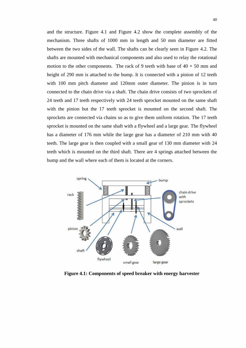
and the structure. Figure 4.1 and Figure 4.2 show the complete assembly of the
mechanism. Three shafts of 1000 mm in length and 50 mm diameter are fitted
between the two sides of the wall. The shafts can be clearly seen in Figure 4.2. The
shafts are mounted with mechanical components and also used to relay the rotational
motion to the other components. The rack of 9 teeth with base of 40 × 50 mm and
height of 290 mm is attached to the bump. It is connected with a pinion of 12 teeth
with 100 mm pitch diameter and 120mm outer diameter. The pinion is in turn
connected to the chain drive via a shaft. The chain drive consists of two sprockets of
24 teeth and 17 teeth respectively with 24 teeth sprocket mounted on the same shaft
with the pinion but the 17 teeth sprocket is mounted on the second shaft. The
sprockets are connected via chains so as to give them uniform rotation. The 17 teeth
sprocket is mounted on the same shaft with a flywheel and a large gear. The flywheel
has a diameter of 176 mm while the large gear has a diameter of 210 mm with 40
teeth. The large gear is then coupled with a small gear of 130 mm diameter with 24
teeth which is mounted on the third shaft. There are 4 springs attached between the
bump and the wall where each of them is located at the corners.
Figure 4.1: Components of speed breaker with energy harvester

41
Figure 4.2: Simulation model
4.3 Working Principle
Rack and pinion is used to convert between linear and rotary motion. Whenever a car
is travels across the speed breaker, the bump is pressed downwards. The rack
attached to the bottom of the bump will move downward which will rotate the pinion.
The pinion will then rotate the larger sprocket of the chain drive via the shaft. The
motion of the chain drive will then rotate the smaller sprocket which eventually
drives the large gear mounted on the same shaft. The large gear will then rotate the
smaller gear which is connected to it. Through multiple series of gear drives as
shown in Figure 4.1 and 4.2, the speed of the rotation of gear is multiplied to higher
speed that is enough to power the generator (not shown in the figures as it does not
contribute to the analysis).
4.4 Constructional Material(s)
Autodesk Inventor provided the Material library which is a collection of material
definitions being defined with its physical properties. The physical properties provide
information on the material composition that will be used for simulation and analysis.
Appropriate material can be assigned to the objects or parts of the design. The

42
following Table 4.1, 4.2 and 4.3 show the type of materials available in Autodesk
Inventor’s Material library being assigned to parts of the speed breaker with energy
harvester and conventional speed breaker together with their information:
Table 4.1: Properties of concrete
Table 4.2: Properties of Steel

43
Yield strength is defined as the stress at which a material begins to deform
plastically. When the stress applied reaches to the yield strength of the material, it
will deform elastically and will return to its original shape when the applied stress is
removed.
Tensile strength is a measurement of the force required to pull something or
an object to the point where it breaks. The tensile strength of a material is the
maximum amount of tensile stress that it can take before failure, for example
breaking.
In this design, it is better for the material to have a high yield strength and
also high tensile strength so that the stress applied to it will not permanently deform.
Thus, it will need a very high stress to cause deformation to the material.
Table 4.3: Properties of stainless steel

44
4.5 Stress Analysis
Stress analysis is used to simulate the response of the design when a stressed is
applied. To imitate a real life situation, forces are added to the design to study its
response. In this project, the force exerted by a car on the bump is assumed to be
20000 N. The input forces in Table 4.4 are forces that are actually being exerted on
the parts being specified in Figure 4.3.
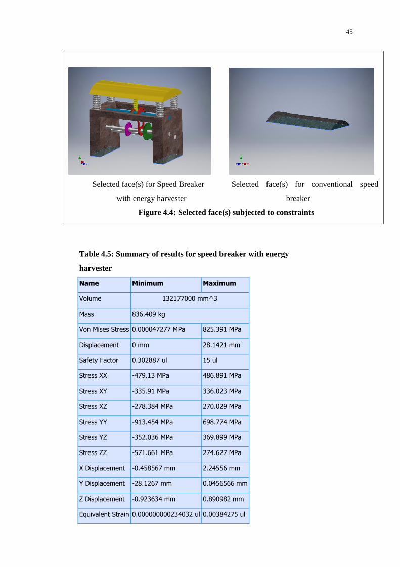
Constraints are also added to mimic environmental conditions. Fixed
constraints in Figure 4.4 are applied to establish grounded effect where there is zero
displacement of the parts specified.
Selected face(s) for Speed Breaker Selected face(s) for conventional
with energy harvester speed breaker
Figure 4.3: Selected face(s) subjected to forces
Table 4.4: A force of 20000N which is the average weight of a car is
applied on the selected faces
Load Type Force
Magnitude 20000.000 N
Vector X 0.000 N
Vector Y -20000.000 N
Vector Z 0.000 N
45
Selected face(s) for Speed Breaker Selected face(s) for conventional speed
with energy harvester breaker
Figure 4.4: Selected face(s) subjected to constraints
Table 4.5: Summary of results for speed breaker with energy
harvester
Name Minimum Maximum
Volume 132177000 mm^3
Mass 836.409 kg
Von Mises Stress 0.000047277 MPa 825.391 MPa
Displacement 0 mm 28.1421 mm
Safety Factor 0.302887 ul 15 ul
Stress XX -479.13 MPa 486.891 MPa
Stress XY -335.91 MPa 336.023 MPa
Stress XZ -278.384 MPa 270.029 MPa
Stress YY -913.454 MPa 698.774 MPa
Stress YZ -352.036 MPa 369.899 MPa
Stress ZZ -571.661 MPa 274.627 MPa
X Displacement -0.458567 mm 2.24556 mm
Y Displacement -28.1267 mm 0.0456566 mm
Z Displacement -0.923634 mm 0.890982 mm
Equivalent Strain 0.000000000234032 ul 0.00384275 ul

46
4.5.1 Von Mises Stress and Strain
The Von Mises stress is computed by Autodesk Inventor. A material is said to yield
when its Von Mises stress reaches a critical value known as the yield strength. The
Von Mises stress is used to predict yielding of materials under any loading condition
from results of simple uniaxial tensile tests.
Strain is the response of a system to an applied stress. When a material is
loaded with a force, it produces a stress, which then causes a material to deform.
Engineering strain is defined as the amount of deformation in the direction of the
applied force divided by the initial length of the material.
Table 4.6: Summary of results for conventional speed breaker
Name Minimum Maximum
Volume 34376800 mm^3
Mass 82.7558 kg
Von Mises Stress 0.0295224 MPa 0.0480435 MPa
Displacement 0 mm 0.000170465 mm
Safety Factor 15 ul 15 ul
Stress XX -0.0108113 MPa 0.00294729 MPa
Stress XY -0.0070022 MPa 0.00699455 MPa
Stress XZ -0.0012459 MPa 0.00128585 MPa
Stress YY -0.0553184 MPa -0.0343404 MPa
Stress YZ -0.00548913 MPa 0.00740543 MPa
Stress ZZ -0.0106217 MPa -0.0016883 MPa
X Displacement -0.0000415742 mm 0.0000416568 mm
Y Displacement -0.00016512 mm 0 mm
Z Displacement -0.0000162248 mm 0.0000257104 mm
Equivalent Strain 0.00000120912 ul 0.0000018945 ul

47
The Autodesk Inventor uses the Von Mises Stress to compute and simulate
the results. The colour contours in both Figure 4.5 and 4.6 indicate the stress and
strain being applied with red as the highest value and blue the lowest value. A force
of 20000N is being applied on the surface of the bump. Both Figures for Von Mises
stress and strain respectively showed the same colour distribution of speed breaker
with energy harvester for the conventional speed breaker.
For the colour distribution across the speed breaker with energy harvester, it
is almost covered with blue with the springs in aqua and some red underneath the
spring which is hidden away. The maximum value for Von Mises stress is 825.4
MPa and minimum value is 0 MPa.
For conventional speed breaker, there is wide range of colours with the
bottom corner slightly covered with red. The maximum value for Von Mises stress is
0.04804 MPa and minimum value of 0.02952 MPa.
These values are being compared with their own yield strength and tensile
strength of the materials used in Table 4.1, 4.2 and 4.3. Therefore, both speed
breakers are able to withstand the stress very well as their Von Mises Stress are way
below the yield and tensile strength of the materials.
Speed breaker with energy harvester Conventional speed breaker
Figure 4.5: Von Mises Stress

48
4.5.2 Displacement
The displacement shows how much the components are being displaced from their
own position. The colour contour shows the blue colour being the minimum value
and red colour being the maximum value of displacement.
The results show that the bump of the speed breaker with energy harvester is
being displaced by nearly 30 mm while there is approximately 0 mm displacement
for the conventional speed breaker when a force of 20000 N is applied. This shows
that for the speed breaker with energy harvester, the springs are being compressed by
30 mm when a normal car is passed by. As for the conventional speed breaker, there
should be no displacement as the whole structure is made from concrete with high
yield and tensile strength.
Speed breaker with energy harvester Conventional speed breaker
Figure 4.6: Strain

49
4.5.3 Safety Factor
All objects are subjected to stress limits which can be represented by their yield or
ultimate strengths. These objects will experience deformation if a stress above this
limit is being applied. So, for a design which is not supposed to permanently deform,
a maximum allowable stress should be less than the material yield strength.
In Autodesk Inventor, the safety factor is the ratio of maximum allowable
stress to the Von Mises Stress. The ratio must be more than 1 for the design to be
acceptable. Anything less than 1 means there are some deformation. In the
simulation, the safety factor will indicate the areas of potential yield. The colour
contour in Figure 4.8 shows a range of colours to indicate the value of safety factor.
Red colour indicates the minimum safety factor of 0 and blue colour with maximum
safety factor of 15.
Based on the simulation of safety factor in Figure 4.8, the safety factor for
conventional speed breaker is more than 1. This means that it will not suffer any
deformation. However, for the speed breaker with energy harvester, it can be seen in
Figure 4.8 that there are areas with safety factor below 1 which are reddish in colour
Speed breaker with energy harvester Conventional speed breaker
Figure 4.7: Displacement

50
with the minimum value of safety factor is 0.3 located underneath the spring. This
means that the spring and also some areas of the bump having a safety factor of less
than 1 will suffer some deformation over a period of time. Thus, the material of the
bump and spring should be changed so that their physical properties will have higher
yield strength.
4.6 Conclusion
Overall, the speed breaker with energy harvester which is designed in this project is
not safe to be implemented based on the result of the safety factor. However, only the
material of the bump and springs are needed to be changed so that their physical
properties are strong enough to withstand the stress and have high yield strength. It
can be seen that, there are no problems with the other components of the design as
they can withstand the Von Mises Stress and have safety factor of more than 1. Thus,
the speed breaker with energy harvester can be implemented once the material of the
suggested parts are changed which could result in safety factor of more than 1.
Speed breaker with energy harvester Conventional speed breaker
Figure 4.8: Safety Factor

51
CHAPTER 5
4 CONCLUSION AND RECOMMENDATIONS
5.1 Conclusion
The utilization of energy proves that we are concerning on the current issues and still
fighting for a better future for the next generation. This project utilizes the traffic
energy which if untapped, will be wasted as heat energy. Rack and pinion
mechanism for harvesting the traffic energy through speed breaker was proposed. It
generates electrical energy that is proportional to the density of vehicles passing
through it. With the impacts study and simulation in this project, we can clear the
doubts of our society on the practicability of implementing the speed breaker as a
traffic energy harvester to provide electricity. As the impacts of the traffic energy
harvester on the speed breakers had been investigated, we can determine the
suitability of the power generation speed breaker to be implemented in large scale.
Through this project, it is found that the design of the speed breaker with rack and
pinion mechanism is insufficient to be implemented on the road. There are great
needs for the improvement and changes in the design so that it is suitable to be
implemented.

52
5.2 Recommendations
In engineering design, it is important to consider the following factors for a good
design:
Cost
Safety
Reliability
Availability of material
Durability
Energy efficiency
So in this project, there are a few recommendations suggested to improve the
design of the rack and pinion mechanism for speed breaker.
1. Bump
The bump that is used in the design is made of concrete. Although it provides a
high yield and tensile strength, it is also heavy. It is better to use material which have
similar properties but also light for the bump. There are bump which are made from
rubber and ABS plastic available in the market. Thus, with a more lightweight
material for the bump, the mechanism is more reliable and durable.
2. Spring
Springs need to be resilient, even when going through numerous compressions
and deflections. A key component to this resiliency is in the spring material. The
choice of material is based on numerous factors ranging from fatigue strength, cost
and availability, corrosion resistance, magnetic permeability and even electrical
conductivity.
3. Ball bearings
The design in this project can be further improve by adding ball bearings to the
shaft. A roller-element bearing is a bearing which carries a load by placing round
elements between the two pieces. The relative motion of the pieces causes the round
elements to roll (tumble) with little sliding. They reduce the friction and transmit the
motion effectively.

53
4. Safety
For safety purposes, the rack and pinion mechanism as energy harvester for the
speed breaker should be installed at one lane of the road instead of the width of the
road. This is to avoid the compression of the bump to affect the vehicles on the other
lane.
5.3 Applications
Power generation with speed breaker can be used in most of the places such as:
Housing area
School area
Toll Plaza
Parking Lot
Traffic Signals
The generated power from the speed breaker is stored in the battery. It can be used
for:
i. Street Lights
A street light which is turned on or lit at a certain time every night. Modern lamps
may also have light-sensitive photocells to turn them on at dusk, off at dawn, or
activate automatically in dark weather.
ii. Traffic Lights
Traffic lights are signalling devices positioned at road intersections, pedestrian
crossings and other locations to control competing flows of traffic.

54
REFERENCES
Amol, S. F., 2015. Air Compression and Electricity Generation by Using Speed
Breaker with Rack And Pinion Mechanism. International Journal Of Modern
Engineering Research. [online] Available at:
<http://www.ijmer.com/papers/Vol5_Issue1/Version-3/C0501_03-2328.pdf>
[Accessed 15 March 2016].
Andriopoulou, S., 2012. A review on energy harvesting from roads. Environmental
Engineering & Sustainable Infrastructure. [online] Available at: <http://kth.diva-
portal.org/smash/get/diva2:549685/FULLTEXT01> [Accessed 15 August 2015].
Aniket, M., Pratik, K. and Atul, K., 2013. Electricity generation from speed breakers.
The International Journal Of Engineering And Science (IJES). [online] Available
at: <http://www.theijes.com/papers/v2-i11/Part.1/E021101025027.pdf> [Accessed
10 August 2015].
Anyaegbunam, F. N. C., 2015. Power generation from a renewable energy source -
speed breaker generators. International Journal of Electrical & Computer
Sciences. [online] Available at: <http://ijens.org/Vol_15_I_05/152205-3939-
IJECS-IJENS.pdf> [Accessed 10 February 2016].Aravind, R., Venkata, S., Yaram,
A. K. and Ramana, R., 2015. Modified design of speed breaker for power
generation. International Journal of Research in Engineering and Technology.
[online] Available at: <
http://esatjournals.org/Volumes/IJRET/2015V04/I14/IJRET20150414018.pdf>
[Accessed 12 August 2015].
Archer, J., Fotheringham, N., Symmons, M. and Corben, B., 2008. The impact of
lowered speed limits in urban and metropolitan areas. [online]: Monash
University Accident Research Centre Report Documentation Page. Available at:
<http://www.monash.edu.au/miri/research/reports/muarc276.pdf> [Accessed 26
July 2015].
Aswathaman, V. and Priyadharshini, M., 2011. Every speed breaker is now a source
of power. 2010 International Conference on Biology, Environment and Chemistry.
Singapore. Available at: <http://www.ipcbee.com/vol1/55-B10014.pdf>
[Accessed 23 August 2015].

55
Indrajit, R. C., 2015. Traffic congestion and environmental quality: a case study of
Kolkata City. International Journal of Humanities and Social Science Invention,
4(7), pp. 20-28.
Kuldeep, S. C., Ayushi, T., Dheeraj, K. and Gaurav, K., 2014. Electricity generation
using power hump with automatic street light control. International Journal of
Engineering and Technical Research. [online] Available at:
<https://www.erpublication.org/admin/vol_issue1/upload%20Image/IJETR_APRI
L_2014_STET_65.pdf> [Accessed 24 February 2016].
Kurowski, P. M., 2012. Engineering Analysis with SolidWorks Simulation 2012.
[online] Available at:
<http://www.deu.edu.tr/userweb/zeki.kiral/CAD/Failure_Assesment.pdf>
[Accessed 24 February 2016].
Mohamad, R., Mahmoud K. and Hicham, E. H., 2015. Using speed bump for power
generation –experimental study. International Conference on Applied Energy.
[online] Available at:
<http://www.sciencedirect.com/science/article/pii/S1876610215009601>
[Accessed 14 February 2016].
Piyush, B., Shubham, G., Navneet, R. and Jegadeeshwaran, 2014. Generation of
electricity with the use of speed breaker. International Journal of Advances in
Engineering & Technology. [online] Available at: <http://www.e-
ijaet.org/media/36I20-IJAET0520963_v7_iss2_589-595.pdf> [Accessed 20 July
2015].
Ramakrishna, P. G. and Ethiraj, G., 2015. Electricity generation by speed breaker.
International Journal of Advanced Research in Electrical, Electronics and
Instrumentation Engineering. [online] Available at:
<http://www.ijareeie.com/upload/2015/may/136_ELECTRICITY.pdf> [Accessed
14 February 2016].
Roads Department, 2000. Axle load surveys [online] Available at:
<http://www.vegvesen.no/_attachment/336324/binary/585461?fast_title=Botswan
a_Guideline+4+-+Axle+Load+Surveys+> [Accessed 20 July 2015].
Sailaja, M., Raja, R. M. and Phani, K. S., 2015. Design of rack and pinion
mechanism for power generation at speed breakers. International Journal of
Engineering Trends and Technology. [online] Available at:
<http://www.ijettjournal.org/2015/volume-22/number-8/IJETT-V22P274.pdf>
[Accessed 15 February 2016].
Santosh, S., Jyothi, and Sudhir, 2014. Design of power generation unit using roller
mechanism. Journal of Electrical and Electronics Engineering. [online] Available
at: <http://iosrjournals.org/iosr-jeee/Papers/Vol9-issue3/Version-1/I09315560.pdf>
[Accessed 23 August 2015].

56
Shakun, S. and Ankit, A., 2011. Produce electricity by the use of speed breakers.
Journal of Engineering Research and Studies. [online] Available at:
<http://www.technicaljournalsonline.com/jers/VOL%20II/JERS%20VOL%20II%
20ISSUE%20II%20APRIL%20JUNE%202011/ARTICLE%2030%20JERS%20V
OL%20II%20ISSUE%20II%20APRIL-%20JUNE%202011.pdf> [Accessed 20
February 2016].
Shehar, B., Anns, N., Abrar, A. and Umer, S., 2015. Power generation using speed
breakers. TELKOMNIKA Indonesian Journal of Electrical Engineering. [online]
Available at:
<http://iaesjournal.com/online//index.php/TELKOMNIKA/article/viewFile/9374/
pdf9374> [Accessed 15 February 2016].
Syed, A. A. and Bilal, M., 2014. Power scavenging from moving vehicles on road.
International Conference on Education and Educational Technology. [online]
Available at: <http://www.superior.edu.pk/ICEET/pdf/research/9.pdf> [Accessed
15 February 2016].
Valsange, P. S., 2012. Design of helical coil compression spring. International
Journal of Engineering Research and Applications. [online] Available at:
<http://www.ijera.com/papers/Vol2_issue6/BY26513522.pdf> [Accessed 18
August 2015].
Venkata, R., Prasada, R., Chiranjeeva, R. and Umamaheswara, R., 2014. Design and
fabrication of power generation system using speed breaker. International Journal
of Current Engineering and Technology. [online] Available at:
<http://inpressco.com/wp-content/uploads/2014/08/Paper762697-2702.pdf>
[Accessed 22 July 2015].
Zeeshan, N., Muhammad, Z. and Abubakr, S., 2014. Design and fabrication of
electricity generation from speed breaker. Bachelor’s Degree. Swedish College of
Engineering & Technology Wah Cantt. Available at:
<http://www.academia.edu/7716724/Design_and_Fabrication_of_Electricity_Gen
eration_from_Speed_breaker_SESSION_2010-2014_PROJECT_SUPERVISOR>
[Accessed 28 August 2015].