investigation on the effect of cooling of the tool using ... · rateofcuttingfluidq(ml/min) q1=...
TRANSCRIPT

Engineering Science and Technology, an International Journal
Contents lists available at ScienceDirect
Engineering Science and Technology,an International Journal
journal homepage: ht tp : / /www.elsevier.com/ locate / jestch
Press: Karabuk University, Press UnitISSN (Printed) : 1302-0056ISSN (Online) : 2215-0986ISSN (E-Mail) : 1308-2043
Available online at www.sciencedirect.com
ScienceDirect
HOSTED BY
19 (2016) 1190–1198
Full Length Article
Investigation on the effect of cooling of the tool using heat pipeduring hard turning with minimal fluid application
a, b
R. Robinson Gnanadurai *, A.S. Varadarajana Department of Mechanical Engineering, Karunya University, Coimbatore, 641114, Tamil Nadu, Indiab Nehru College of Engineering and Research Centre, Pampady, Thrissur 680597, Kerala, IndiaA R T I C L E I N F O
Article history:Received 14 November 2015Accepted 29 January 2016Available online
Keyword:Hard turningMinimal fluid applicationPulsed jetHeat pipe
A B S T R A C T
Hard turning with minimal fluid application is a recently developed technique to alleviate the problemassociated with cutting fluid. During this process, very small quantity of cutting fluid is applied as a narrowhigh velocity pulsing jet at the cutting zone. As the quantity of cutting fluid is very small, some auxil-iary cooling of tool using heat pipe was attempted in the present work to enhance heat dissipation andthus improving cutting performance. Heat pipe was installed in vertical position in contact with the toolfor extracting more heat from the tool. The influence of heat pipe cooling of tool on the cutting perfor-mance was analyzed by Taguchi’s design of experiments. It was observed that the use of heat pipe inminimal fluid application reduced cutting temperature and tool wear to a maximum of 22% and 15%,respectively, in comparison with conventional hard turning with minimal fluid application without theaid of heat pipe. It appears that heat pipe can be successively employed as a mean of cooling the toolduring hard turning with minimal fluid application.
BY-NC-ND license (http://creativecommons.org/ licenses/by-nc-nd/4.0/).This is an open access article under the CC© Karabuk University. Publishing services by Elsevier B.V.
March 201624
2016
1. Introduction
Hard turning process inherently generates high cutting temper-ature due to high hardness of the work piece and the existence ofhigh friction at the tool–chip interface and the tool–work inter-face. The tool life in the hard turning is commonly improved bysupplying large quantity of cutting fluid. However, the introduc-tion of cutting fluid brings forth health and safety concerns [1,2].In addition, the cost of procurement, storage and disposal of cuttingfluids is several times higher than tool cost [3]. Due to the techno-logical innovations such as ultra-hard tool materials, new toolcoatings material, and optimized tool geometry, machining withoutcutting fluid called dry turning is developed. However in dry turningoperations, the friction and adhesion between chip and tool tendto be higher which causes higher temperatures, higher wear ratesand consequently shorter tool lives. Further, dry turning needs ex-tremely rigid machine tool which is difficult to implement on theshop floor with the existing machine tools. All these problems relatedto turning with conventional flood cooling and pure dry turning leadto research on machining with minimal fluid application [4] as analternative.
* Corresponding author. Tel.: +91 09894575243, fax: +91 04222615615.E-mail address: [email protected] (R. Robinson Gnanadurai).Peer review under responsibility of Karabuk University.
http://dx.doi.org/10.1016/j.jestch.2016.01.012
2215-0986/� Karabuk University. Publishing services by Elsevier B.V.This is an open access article under the CC BY-NC-ND license (http://creativecommons.or
2016
Machining with minimal fluid application (MFA) is a techniqueto minimize the use of cutting fluid on the shop floor. In this tech-nique, extremely small (2 to 5 ml) quantities of proprietary cuttingfluid are applied at the critical zones as a pulsed jet. It is reportedthat the frictional forces between two sliding surfaces can be reducedby rapidly fluctuating the width of the lubricant filled gap sepa-rating them [5]. This principle was used for developing the minimalcutting fluid application system for minimizing the consumptionof cutting fluid in machining. In MFA, fluctuation of width of lu-brication that is filled in the gap between the tool rake face, andthe chip is achieved with a high velocity narrow pulsing jet. It isreported [6–8] that this new technique not only reduced the usageof cutting fluid drastically but offered better cutting performanceas well when compared to wet turning.
In minimal fluid application, extremely small quantity of cuttingfluid in the order of 2 ml/min is available for the dual purpose ofcooling and lubrication. Extreme temperature conditions that existnear the root of the chip may cause the thermal degradation of thecutting fluid. Due to this, cutting fluid loses its lubrication proper-ty and fails to reduce frictional condition at the cutting zone. If someauxiliary cooling means is designed to cool the tool would avoidthe degradation of cutting fluid and improve the cutting perfor-mance. Heat pipes can be successfully used for removing heat inmany applications as found in the literatures. Use of heat pipe inmachining for cooling the tool can reduce the amount of cuttingfluid used and the associated environmental pollution. The review
g/licenses/by-nc-nd/4.0/).

dissipation from the tool which helped in reducing of tempera-ture at tool chip interface.
Review of literatures indicated that cutting performance can beimproved by introducing heat pipes for removal of heat from thecutting tools. Heat pipe assisted cooling system can reduce or elim-inate the use of cutting fluids and the associated environmentalpollution. Moreover, the above literature clearly revealed that nostudy has been made related to the application of heat pipe in thearea of machining with minimal fluid application.
In the present research work, an attempt was made to investi-gate the applicability of heat pipes in cooling the cutting tool duringhard turning with minimal fluid application. The objective is to in-vestigate the effect of heat pipe cooling of tool on cutting force, toolwear, surface finish and cutting temperature during turning of hard-ened AISI 4340 steel with minimal fluid application usingmulticoated carbide insert.
3. Experimental procedures
Cutting experiments were conducted on a Kirloskar Turn master-35 lathe to study the influence of heat pipe assisted cooling of cuttingtool on cutting performance during minimal fluid application. AISI4340 steel with hardness of 45 HRC was used as work material.Cutting tool consisted of tungsten carbide inserts with sculpturedrake face with a specification SNMG 120408 and a tool holder PSBNR2525M12 by Taegutec were used in the experiments. Since the quan-tity of cutting fluid used is extremely small, a specially formulatedcutting fluid was employed in this investigation. The formulationconsisted of petroleum sulfonate (15% by weight), ethylene glycol(1% by weight), oleic acid (3% by weight), triethanol amine (3% byweight), alcohol ethoxylate (3% by weight) and paraffinic mineraloil (rest) [19,20]. It acted as oil in water emulsion. Petroleum sul-fonate acts as an emulsifier, rust inhibitor, surfactant and EP agent.Ethylene glycol resists freezing due to its low freezing point and actsas a coupling agent to increase the stability of the emulsion. Oleicacid is used as an emulsifying or solubilizing agent in aerosol prod-ucts. It serves as an agent for improving the lubricity of the cuttingfluid. Triethaol Amine is used to provide the alkalinity needed toprotect the work against rusting and it acts as an antioxidant. It alsocontrols the evaporation rate of water in cutting fluid. Alcoholethoxylates possess greater resistance to water hardness than manyother surfactants. Commercially available paraffinic mineral oil wasused as base.
Cutting fluid was applied at the tool work interface with the helpof a minimal fluid applicator. Minimum fluid applicator shown inFig. 1 can deliver very small quantity of cutting fluid in the formof high velocity pulsing jet and has the facility to vary the
Fig. 1. Minimal fluid application system.
R.R. Gnanadurai, A.S. Varadarajan/Engineering Science and Technology, an International Journal 19 (2016) 1190−1198 1191
of literatures clearly revealed that, no study has been made in re-lation to the application of heat pipe in the area of machining withminimal fluid application. Hence, in order to achieve the effectivecooling of the tool during machining with minimal fluid applica-tion, use of heat pipe is explored in the present work.
2. Literature review
Heat pipe is a heat transfer device with a very high thermal con-ductance. It is used to transport heat from one location to anotherwithout the need for an external power supply by diffusion [9]. Aheat pipe consists of an evacuated container sealed at ends, a wickstructure, and a small amount of working fluid in equilibrium withits own vapor. A heat pipe has three sections namely evaporatorsection, adiabatic (transport) section, and condenser section. Theexternal heat load on the evaporator section causes the working fluidto vaporize. The resulting vapor pressure drives the vapor throughthe adiabatic section to the condenser section. In the adiabaticsection, no heat is absorbed or rejected. The condensing section con-denses the vapor and the latent heat of vaporization of the workingfluid is rejected into the atmosphere. The condensed working fluidis then pumped back by capillary pressure generated in the wickstructure. Transport of heat can be continuous as long as there isenough heat input to the evaporator section so that sufficient cap-illary pressure is generated to drive the condensed liquid back tothe evaporator. Large quantities of heat can be transported througha small cross-sectional area over a considerable distance with noadditional power input to the system using heat pipe when com-pared to other conventional methods of heat transfer.
Heat pipes are used for cooling purposes in a wide range of ap-plications. Recently, it found its application in the field ofmanufacturing to control the process temperatures in die-casting,injection molding and metal machining. Application of heat pipein metal machining as an alternative to conventional method of re-moving heat from the cutting zone is an emerging area of interestamong researchers. Cooling of cutting tool reduces cutting tem-perature and improves the tool life by reducing tool wear [10–13].
Noorul Hag et al. [14] investigated the effect of parameters suchas diameter of heat pipe, length of heat pipe, magnitude of vacuumin the heat pipe and the material used for making heat pipe oncutting performance. Heat transfer efficiency of heat pipe duringhard turning of engine crank pin material using mixed alumina insertwas studied. A set of heat pipe parameters for optimum perfor-mance were arrived at by performing a nine run experiment. Therewas considerable improvement in tool life when a 400 mm Hgvacuum was maintained in a heat pipe made of brass having length40 mm and diameter 7 mm was used.
Liang et al. [15] studied the effect of heat pipe in reducing thetool–chip interface temperature of the cutter with a flat heat pipeattached on the rake face of insert in dry turning. The results showedthat the tool–chip interface temperature could be reduced effec-tively for the cutter with heat pipe cooling and the reduction intemperature is found to be more at the higher cutting speed. Zhuet al. [16] experimentally verified the feasibility and effectivenessof heat-pipe cooling in end-milling operations. The result demon-strated that use of heat pipe cooling reduced the tool wear andprolonged the tool life of end mill cutter.
Zhu et al. [17] made a numerical study in order to investigatethe effect of heat pipe cooling in drilling operations by predictingthe thermal, structural static and dynamic characteristics of the tool.The numerical simulation indicated that heat pipe assisted drill-ing reduced the peak temperature and stress on the tool tip whencompared to dry drilling. Liang et al. [18] estimated the amount ofheat flowed into the turning tool and that carried away by the heatpipe. It is found that the presence of heat pipe increased the amountof heat flowing into the tool and also increased the amount of heat

injection pressure (up to 120 Bar), frequency of pulsing (up to 1000pulses/min) and rate of delivery of cutting fluid (up to 30 ml/min)independently.
Heat pipe used in this research work was made of electrolyticcopper and water was used as working fluid. Before filling water,presence of non-condensable gases if any, was removed by evac-uation using a vacuum pump. Water was filled inside the tube ata pressure of 10−3 millibar in order to lower the boiling point of water.The inlet passage of water was crimped and sealed.
Before selecting the structural parameters of heat pipe, authorsconducted preliminary experiments for optimizing the type of wickstructure, orientation and the location of heat pipe. Accordingly,grooved type wick having an axial groove along the length of heatpipe has been selected for the study in order to circulate the workingfluid inside the heat pipe with less flow resistance than other typesof wicks such as mesh and sintered powder types [21]. The con-denser section of the heat pipe was provided with cooling fins of10 mm width and 0.5 mm thickness over a length of 75 mm. In orderto cool the fins, air was blown against the cooling fins with a speedof 500 m/min using a fan. The line sketch of the fabricated heat pipewith dimension is shown in Fig. 2. The detailed structural param-eters of heat pipe are presented in Table 1.
The tool holder was provided with a 6.5 mm hole on the top faceusing EDM process for mounting the heat pipe in vertical posi-tion. The location of the hole was selected in such a way that therewas adequate surface contact between the heat pipe and the toolinsert. Thermal cement with high thermal conductivity was usedto fix the heat pipes to the tool holder to ensure good thermal contactbetween the insert and the heat pipe. Assembly of tool holder withheat pipe is schematically shown in Fig. 3.
Photograph of the experimental setup is shown in Fig. 4. A sixteenrun experiment was designed based on Taguchi’s technique [22],and the input parameters were varied at two levels. The input pa-rameter and their respective levels are given in Table 2. The design
Fig. 2. Line sketch of heat pipe.
Table 1Structural parameters of heat pipe.
Structural parameters Value
Length of evaporator, mm 10Length of adiabatic section, mm 5Length of condenser, mm 75Outer radius of heat pipe, mm ϕ6.3Heat pipe wall thickness, mm 1Fin width, mm 10Fin thickness, mm 0.5Fin length, mm 75Wall material Electrolytic copperWick type GroovedGroove dimension ,mm 0.5 × 0.5Spacing between grooves, mm 1Working fluid of heat pipe WaterWorking fluid charge level 30% of heat pipe volume is filled (0.45 ml)
Fig. 3. Assembly of tool holder and heat pipe.
Fig. 4. Photograph of the experimental setup for evaluating the cutting perfor-mance during cooling of tool using heat pipe.
R.R. Gnanadurai, A.S. Varadarajan/Engineering Science and Technology, an International Journal 19 (2016) 1190−1198
1192

matrix for the 16 run experiment is shown in Table 3. For each trial,the cutting time was fixed as 60 seconds and the experiments werecarried out in random order with two replications. The list of pa-rameters that were kept constant is shown in Table 4.
Cutting force was measured using a Kistler three component9257B dynamometer with an uncertainty ±0.1 N. The cutting tem-perature was measured using an extrapolative technique developed
by Varadarajan et al. [23] based on Finite Element Analysis. Two stan-dard K type thermocouples of uncertainty ±0.2 °C were planted atthe interface between the cutting tool insert and the holder sym-metrically. The bottom of the insert and the two sides were insulatedfor thermal isolation of the insert from the tool holder. The tem-perature was measured simultaneously by two thermocouples afterachieving steady state condition in the insert. A correlation was de-veloped between the temperature measured at the interface betweenthe cutting tool insert and the holder and the average tempera-ture of the tool tip using finite element model which was validatedusing tool work thermo couple technique. Flank wear was mea-sured using a tool maker’s microscope (with an uncertainty of±0.01 mm), and the tool chip contact length was measured usinga profile projector (with an uncertainty of ±0.01 mm). Surfaceroughness was measured using a stylus type TIME-TR100 surfaceroughness tester with an uncertainty of ±1.5%. A tool life test wascarried out for studying the variation of flank wear and surfaceroughness with respect to time.
4. Results and discussion
The average values of observations made during the 16 run ex-periment are presented in Table 5. The observations were analyzedusing Qulitek-4 software, and the set of levels of the input param-eters for achieving optimum performance is presented in Table 6.It was observed that the presence of heat pipe forms the most sig-nificant parameter influencing the cutting temperature, cutting force,surface roughness, flank wear and tool chip contact length.
It was also observed that the rate of fluid application is to be keptat level 2 (8 ml/min) and the frequency of pulsing at level 1 (300pulses/min) for achieving better cutting performance. When the fre-quency of pulsing was kept at lower level (Level 1) and the rate offluid application at higher level (Level 2), the amount of cutting fluiddelivered per pulse is more than that is possible when the rate offluid application was kept at lower level 1 (2 ml/min) and the fre-quency of pulsing at higher level (700 pulses/min). If the quantityof cutting fluid delivered per pulse is very small, the fluid par-ticles will not have sufficient kinetic energy to penetrate into thetool work interface and reach the tool chip interface through themicrocracks on the work material near the tool tip.
When the frequency of pulsing kept at level 1 (300 pulses permin) and the rate of fluid application at higher level (8 ml/min), theamount of cutting fluid delivered per pulse will be considerably highand the fluid particles will have the requisite kinetic energy to pen-etrate into the tool–chip interface leading to better rake face
Table 2Input parameters and their levels.
Parameter Level 1 Level 2
Rate of cutting fluid q (ml/min) q1 = 2 q2 = 8Frequency of pulsing F (pulses/min) F1 = 300 F2 = 700Composition C (% of oil in water) C1 = 5 C2 = 15Heat pipe (HP) HP0
Without heat pipeHP1With heat pipe
Table 3Design matrix for 16 run experiment.
Exp. no Rate of cuttingfluid (q)
Frequency ofpulsing (F)
Composition(C)
Heat pipe(HP)
1 q1 F1 C1 HP12 q1 F1 C1 HP03 q1 F1 C2 HP14 q1 F1 C2 HP05 q1 F2 C1 HP16 q1 F2 C1 HP07 q1 F2 C2 HP18 q1 F2 C2 HP09 q2 F1 C1 HP110 q2 F1 C1 HP011 q2 F1 C2 HP112 q2 F1 C2 HP013 q2 F2 C1 HP114 q2 F2 C1 HP015 q2 F2 C2 HP116 q2 F2 C2 HP0
Table 4List of parameters that were kept constant.
Parameter Value
Pressure of cutting fluid (p) 80 BarCutting Velocity (V) 80 m/minFeed (f) 0.1 mm/revDepth of Cut (d) 1.25 mm
Table 5Observations during the cutting experiments.
Exp. No. Cutting temperature, T (°C) Main cutting force, Fz (N) Surface finish, Ra (μm) Flank wear, VB (mm) Tool chip Contact Length, L (mm)
R1 R2 Avg. R1 R2 Avg. R1 R2 Avg. R1 R2 Avg. R1 R2 Avg.
1 142.6 144.5 143.55 145.82 149.22 147.52 3.45 3.21 3.33 0.05 0.07 0.06 0.04 0.06 0.052 156.32 150.78 153.55 131.66 117.42 124.54 1.72 1.6 1.66 0.05 0.03 0.04 0.03 0.01 0.023 209.45 215.95 212.7 147.91 154.21 151.06 2.43 3.51 2.97 0.06 0.04 0.05 0.03 0.03 0.034 141.84 144.98 143.41 130.2 143.5 136.85 1.22 1.56 1.39 0.03 0.03 0.03 0.02 0.04 0.035 173.78 167.12 170.45 191.25 187.65 189.45 2.67 3.01 2.84 0.07 0.07 0.07 0.09 0.07 0.086 152.81 144.99 148.9 158.29 146.01 152.15 1.92 1.32 1.62 0.04 0.06 0.05 0.07 0.03 0.057 201.62 215.34 208.48 140.31 148.47 144.39 3.1 2.4 2.75 0.05 0.07 0.06 0.03 0.07 0.058 107.21 105.25 106.23 149.02 145.38 147.2 1.98 1.66 1.82 0.07 0.09 0.08 0.04 0.04 0.049 182.33 188.43 185.38 150.29 154.09 152.19 2.46 2.94 2.7 0.1 0.08 0.09 0.03 0.05 0.0410 129.3 127.94 128.62 144.95 140.01 142.48 1.25 1.81 1.53 0.03 0.05 0.04 0.03 0.03 0.0311 186.2 183.44 184.82 150.67 144.77 147.72 3.2 2.76 2.98 0.05 0.05 0.05 0.05 0.03 0.0412 120.92 118.3 119.61 140.12 133.86 136.99 1.61 1.83 1.72 0.09 0.05 0.07 0.07 0.03 0.0513 198.56 184.6 191.58 184.74 174.56 179.65 2.76 3.16 2.96 0.05 0.03 0.04 0.09 0.01 0.0514 137.22 139.46 138.34 152.2 159.8 156 1.6 1.88 1.74 0.04 0.04 0.04 0.04 0.04 0.0415 220.12 223.88 222 148.69 152.13 150.41 2.55 3.11 2.83 0.04 0.06 0.05 0.04 0.06 0.0516 105.32 112.22 108.77 140.34 145.08 142.71 1.67 1.73 1.7 0.03 0.03 0.03 0.03 0.05 0.04
R.R. Gnanadurai, A.S. Varadarajan/Engineering Science and Technology, an International Journal 19 (2016) 1190 1198 1193

lubrication and to some extent enhanced cooling as the dropletsevaporate.
It was observed that the composition of cutting fluid should bekept at level 2 (15% oil) for achieving better cutting performance.Presence of oil rich cutting fluid at the tool chip interface acted asdielectric preventing the surface interaction between tool rake faceand underside of chip, which prevented the sticking of the chip ontothe rake face and improves rake face lubrication. Due to this, thefriction condition at the tool chip interface turns from sticking tosliding which brought forth reduction of cutting force. The reduc-tion in cutting force led to reduction in tool wear and improvementin surface finish.
The relative significance of the operating parameters on cuttingtemperature, main cutting force, surface roughness average and flankwear are shown in Fig. 5(a)–(d) respectively. It can be found thatheat pipe has the most significant effect on improving cutting per-formance among the other parameters selected for the study.
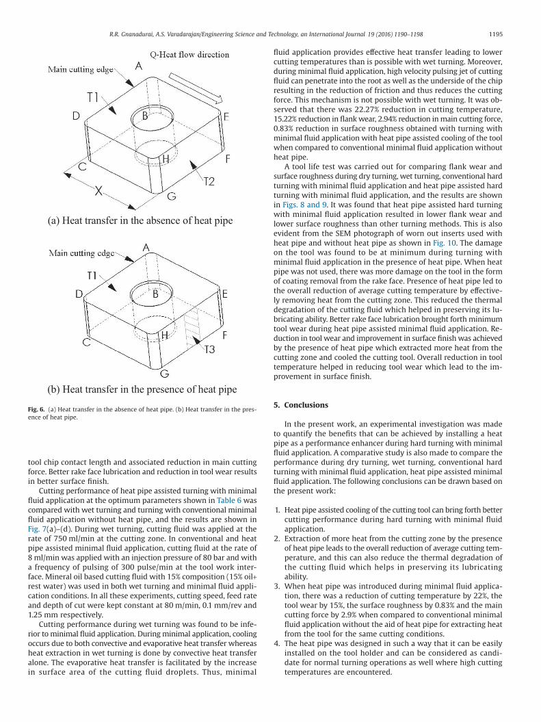
When the heat pipe was not installed (Fig. 6(a)), let T1 be theaverage cutting temperature at the face ABCD of the insert and T2
that of the face EFGH. If k is the thermal conductivity of thematerial of the insert, A is the area of a side face of insert and x isthe distance between the faces ABCD and EFGH, the rate of heat (Q1)transferred from the face ABCD to EFGH is given by
Q kAT T
x11 2= −⎛
⎝⎜⎞⎠⎟
(1)
When the heat pipe was installed (Fig. 6(b)), let T3 be the averagetemperature at the surface EFGH. The rate of heat (Q2) transferredis given by
Q kAT T
x21 3= −⎛
⎝⎜⎞⎠⎟
(2)
Because of the presence of the heat pipe, the face EFGH will becooled and hence T3 < T2, and from the Eqs. (1) and (2), it can beseen that Q2 > Q1. When more heat is transferred from the face ABCD,the severity of temperature related damages of the tool tip reduceswhich is evident in Fig. 7.
Average cutting temperature is considered as the factor that ac-celerates all forms of tool wear. Hence when heat generated on thetool is removed at faster rate, the mechanisms responsible for toolwear of different forms become less active leading to the reduc-tion in tool wear. Rapid removal of heat from the contact zone madepossible by the presence of heat pipe leads to overall reduction ofaverage cutting temperature, and this can also reduce the thermaldegradation of the cutting fluid which helps in preserving its lu-bricating ability. This causes the conditions in the contact zone tochange from sticking to one of sliding. This leads to reduction in
Table 6Levels of operating parameters for optimum performance.
Factor Optimum level
Rate of minimal cutting fluid, q (ml/min) 8Frequency of pulsing, F (pulses/min) 300Composition of minimal cutting fluid, C (%) 15Heat pipe, (HP) HP1
With heat pipe
(a) (b)
(c) (d)
140142144146148150152154156158160
2 8 300 700 5 15 HP0 HP1
Mai
n C
uttin
g Fo
rce,
Fz
(N)
Level of Parameters
120
130
140
150
160
170
180
190
200
2 8 300 700 5 15 HP0 HP1
Cut
ting
Tem
pera
ture
, T (o C
)
Level of Parameters
11.21.41.61.8
22.22.42.62.8
3
2 8 300 700 5 15 HP0 HP1
Surf
ace
Rou
ghne
ss, R
a(µ
m)
Level of Parameters
0.03
0.035
0.04
0.045
0.05
0.055
0.06
0.065
0.07
2 8 300 700 5 15 HP0 HP1
Flan
k W
ear,
VB
(mm
)
Level of Parameters
Fig. 5. Relative significance of the operating parameters on (a) main cutting force, (b) cutting temperature, (c) surface roughness and (d) flank wear.
R.R. Gnanadurai, A.S. Varadarajan/Engineering Science and Technology, an International Journal 19 (2016) 1190−1198 1194
tool chip contact length and associated reduction in main cuttingforce. Better rake face lubrication and reduction in tool wear resultsin better surface finish.
Cutting performance of heat pipe assisted turning with minimalfluid application at the optimum parameters shown in Table 6 wascompared with wet turning and turning with conventional minimalfluid application without heat pipe, and the results are shown inFig. 7(a)–(d). During wet turning, cutting fluid was applied at therate of 750 ml/min at the cutting zone. In conventional and heatpipe assisted minimal fluid application, cutting fluid at the rate of8 ml/min was applied with an injection pressure of 80 bar and witha frequency of pulsing of 300 pulse/min at the tool work inter-face. Mineral oil based cutting fluid with 15% composition (15% oil+rest water) was used in both wet turning and minimal fluid appli-cation conditions. In all these experiments, cutting speed, feed rateand depth of cut were kept constant at 80 m/min, 0.1 mm/rev and1.25 mm respectively.
Cutting performance during wet turning was found to be infe-rior to minimal fluid application. During minimal application, coolingoccurs due to both convective and evaporative heat transfer whereasheat extraction in wet turning is done by convective heat transferalone. The evaporative heat transfer is facilitated by the increasein surface area of the cutting fluid droplets. Thus, minimal
fluid application provides effective heat transfer leading to lowercutting temperatures than is possible with wet turning. Moreover,during minimal fluid application, high velocity pulsing jet of cuttingfluid can penetrate into the root as well as the underside of the chipresulting in the reduction of friction and thus reduces the cuttingforce. This mechanism is not possible with wet turning. It was ob-served that there was 22.27% reduction in cutting temperature,15.22% reduction in flank wear, 2.94% reduction in main cutting force,0.83% reduction in surface roughness obtained with turning withminimal fluid application with heat pipe assisted cooling of the toolwhen compared to conventional minimal fluid application withoutheat pipe.
A tool life test was carried out for comparing flank wear andsurface roughness during dry turning, wet turning, conventional hardturning with minimal fluid application and heat pipe assisted hardturning with minimal fluid application, and the results are shownin Figs. 8 and 9. It was found that heat pipe assisted hard turningwith minimal fluid application resulted in lower flank wear andlower surface roughness than other turning methods. This is alsoevident from the SEM photograph of worn out inserts used withheat pipe and without heat pipe as shown in Fig. 10. The damageon the tool was found to be at minimum during turning withminimal fluid application in the presence of heat pipe. When heatpipe was not used, there was more damage on the tool in the formof coating removal from the rake face. Presence of heat pipe led tothe overall reduction of average cutting temperature by effective-ly removing heat from the cutting zone. This reduced the thermaldegradation of the cutting fluid which helped in preserving its lu-bricating ability. Better rake face lubrication brought forth minimumtool wear during heat pipe assisted minimal fluid application. Re-duction in tool wear and improvement in surface finish was achievedby the presence of heat pipe which extracted more heat from thecutting zone and cooled the cutting tool. Overall reduction in tooltemperature helped in reducing tool wear which lead to the im-provement in surface finish.
5. Conclusions
In the present work, an experimental investigation was madeto quantify the benefits that can be achieved by installing a heatpipe as a performance enhancer during hard turning with minimalfluid application. A comparative study is also made to compare theperformance during dry turning, wet turning, conventional hardturning with minimal fluid application, heat pipe assisted minimalfluid application. The following conclusions can be drawn based onthe present work:
1. Heat pipe assisted cooling of the cutting tool can bring forth bettercutting performance during hard turning with minimal fluidapplication.
2. Extraction of more heat from the cutting zone by the presenceof heat pipe leads to the overall reduction of average cutting tem-perature, and this can also reduce the thermal degradation ofthe cutting fluid which helps in preserving its lubricatingability.
3. When heat pipe was introduced during minimal fluid applica-tion, there was a reduction of cutting temperature by 22%, thetool wear by 15%, the surface roughness by 0.83% and the maincutting force by 2.9% when compared to conventional minimalfluid application without the aid of heat pipe for extracting heatfrom the tool for the same cutting conditions.
4. The heat pipe was designed in such a way that it can be easilyinstalled on the tool holder and can be considered as candi-date for normal turning operations as well where high cuttingtemperatures are encountered.
(a) Heat transfer in the absence of heat pipe
(b) Heat transfer in the presence of heat pipe
Fig. 6. (a) Heat transfer in the absence of heat pipe. (b) Heat transfer in the pres-ence of heat pipe.
R.R. Gnanadurai, A.S. Varadarajan/Engineering Science and Technology, an International Journal 19 (2016) 1190−1198 1195

(a) (b)
(c) (d)
125
130
135
140
145
150
Wet Turning Conventional MinimalFluid Application
(MFA)
Heat pipe assistedMFA
Mai
n C
uttin
g Fo
rce
(N)
Different Cooling Methods
0
50
100
150
200
250
300
Wet Turning Conventional MinimalFluid Application
(MFA)
Heat pipe assistedMFA
Cut
ting
Tem
pera
ture
(o C)
Different Cooling Methods
0
0.02
0.04
0.06
0.08
0.1
0.12
Wet Turning Conventional MinimalFluid Application
(MFA)
Heat pipe assistedMFA
Flan
k W
ear (
mm
)
Different Cooling Methods
1.16
1.18
1.2
1.22
1.24
1.26
1.28
Wet Turning Conventional MinimalFluid Application
(MFA)
Heat pipe assistedMFA
Different Cooling Methods
Fig. 7. Comparison of (a) main cutting force, (b) cutting temperature, (c) flank wear and (d) surface roughness during wet turning, conventional minimal fluid applicationand minimal fluid application with heat pipe assisted cooling of tool.
00.020.040.060.080.1
0.120.140.160.180.2
0.22
0 50 100 150 200
Flan
k W
ear,
VB
(mm
)
Time (Sec)
Dry turningWet TurningTurning with MFAHeat pipe assited turning with MFA
Fig. 8. Variation of flank wear for different turning methods.
R.R. Gnanadurai, A.S. Varadarajan/Engineering Science and Technology, an International Journal 19 (2016) 1190−1198 1196

Acknowledgements
The authors are grateful to the Centre for Research in Design andManufacturing Engineering (CRDM) of School of Mechanical Sci-ences, Karunya University for providing the facilities to carry outthis research work. The authors would like to thank Mr. J. Jones Robin,Mr. Siva Sankaran and Mr. Jeya Seelan for their assistance. They aregrateful to M/s Taegu Tec for supporting this research work by pro-viding cutting inserts.
Nomenclature
MFA Minimal fluid applicationEDM Electrical discharge machiningV Cutting velocity [m/min]q Rate of cutting fluid [ml/min]N Frequency of pulsing [pulses/min]p Pressure of cutting fluid [bar]Fz Main cutting force [N]T Cutting temperature [°C]Ra Surface roughness [μm]VB Flank wear [mm]Q Rate of heat transfer [J/s]A Area of heat transfer [m2]k Thermal conductivity [W/mK]
References
[1] J.W. Sutherland, V.N. Kulur, N.C. King, An experimental investigation of airquality in wet and dry turning, CIRP Ann. 49 (2000) 61–64.
[2] M. Sokovic, K. Mijanovic, Ecological aspects of the cutting fluids and its influenceon quantifiable parameters of the cutting processes, J. Mater. Process. Technol.109 (2001) 181–189.
[3] F. Klocke, G. Eisenblatter, Dry cutting, CIRP Ann. 46 (1997) 519–526.[4] A.S. Varadarajan, P.K. Philip, B. Ramamoorthy, Investigations on hard turning
with minimal cutting fluid application (HTMF) and its comparison with dryand wet turning, Int. J. Mach. Tool. Manu. 42 (2002) 193–200.
[5] Uzi Landman, ‘Frustrated’ lubricant molecules offer new strategy for reducingfriction in mechanical devices, Georgia Tech–Research News (1998)<http://gtresearchnews.gatech.edu/newsrelease/FRICTION.html> (Accessed23.05.15).
[6] P.K. Philip, A.S. Varadarajan, B. Ramamoorthy, Influence of cuttingfluid composition and delivery variables on performance in hardturning using minimal fluid in pulsed jet form, J. Inst. Eng. (India) 82 (2001)12–19.
[7] N.R. Dhar, M.T. Ahmed, S. Islam, An experimental investigation on effect ofminimum quantity lubrication in machining AISI 1040 steel, Int. J. Mach. Tool.Manu. 47 (2007) 748–753.
[8] R. Robinson Gnanadurai, A.S. Varadarajan, The effect of an auxiliary pulsing jetof cutting fluid on cutting performance during hard turning with minimal fluidapplication, Int. J. Mach. Mach. Mater. 12 (2012) 321–336.
[9] A. Faghri, Heat Pipe Science and Technology, Taylor and Francis, Washington,DC, 1995. ISBN 978-1-56032-383-9.
[10] T.C. Jen, G. Gutierrez, S. Eapen, G. Barber, H. Zhao, P.S. Szuba, et al.,Investigation of heat pipe cooling in drilling applications. Part I: preliminarynumerical analysis and verification, Int. J. Mach. Tool. Manu. 42 (2000)643–652.
[11] H. Zhao, G.C. Barber, Q. Zou, A study of flank wear in orthogonal cutting withinternal cooling, Wear 253 (2002) 957–962.
1.15
1.25
1.35
1.45
1.55
1.65
1.75
0 50 100 150 200
Surf
ace
Rou
ghne
ss, R
a(µ
m)
Time (Sec)
Dry turningWet TurningTurning with MFAHeat pipe assited turning with MFA
Fig. 9. Variation of surface roughness for different machining conditions.
a) without heat pipe b) with heat pipe
Fig. 10. SEM photograph of worn out inserts used during turning with minimal fluid application and during minimal fluid application in the presence of heat pipe.
R.R. Gnanadurai, A.S. Varadarajan/Engineering Science and Technology, an International Journal 19 (2016) 1190−1198 1197

[12] R.Y. Chiou, V. Aynbinder, L.G. Stepanskiy, L. Lu, S. Rauniar, J.S.M. Chen, et al.,Analytical study of the effect of heat pipe cooling in machining. Proceedingsof ASME IMECE 2005, Paper No. IMECE2005-79344, 13–21, 2005.
[13] R.Y. Chiou, L. Lu, J.S.J. Chen, M.T. North, Investigation of dry machining withembedded heat pipe cooling by finite element analysis and experiments, Int.J. Adv. Manuf. Technol. 31 (2007) 905–914.
[14] A. Noorul Haq, T. Tamizharasan, Investigation of the effects of coolingin hard turning operations, Int. J. Adv. Manuf. Technol. 30 (2006) 808–816.
[15] L. Liang, Y. Quan, Z. Ke, Investigation of tool-chip interface temperature in dryturning assisted by heat pipe cooling, Int. J. Adv. Manuf. Technol. 54 (2011)35–43.
[16] L. Zhu, T.C. Jen, C.L. Yin, X.L. Kong, Y.H. Yen, Experimental analyses to investigatethe feasibility and effectiveness in using heat-pipe embedded end-mills, Int.J. Adv. Manuf. Technol. 60 (2012) 497–504.
[17] L. Zhu, T.C. Jen, C.L. Yin, X.L. Kong, Y.H. Yen, Investigation of the feasibility andeffectiveness in using heat pipe-embedded drills by finite element analysis, Int.J. Adv. Manuf. Technol. 64 (2013) 659–668.
[18] L. Liang, Y. Quan, Investigation of heat partition in dry turningassisted by heat pipe cooling, Int. J. Adv. Manuf. Technol. 66 (2013) 1931–1941.
[19] A.S. Varadarajan, B. Ramamoorthy, P.K. Philip, Formulation of a cutting fluidfor hard turning with minimal cutting fluid, 20th AIMTDR Conference, BirlaInstitute of Technology, Ranchi, India, 201–205, 2002.
[20] P. Sam Paul, A.S. Varadarajan, R. Robinson Gnanadurai, Study on the influenceof fluid application parameters on tool vibration and cutting performance duringturning of hardened steel, Eng. Sci. Technol. Int. J. 19 (1) (2015) 241–253,doi:10.1016/j.jestch.2015.07.017.
[21] F.B. Nishida, L.S. Marquardt, V.Y.S. Borges, P.H.D. Santos, T.A. Alves, Developmentof a copper heat pipe with axial grooves manufactured using wire electricaldischarge machining (Wire-EDM), Adv. Mater. Res. 1120–1121 (2015) 1325–1329.
[22] R.H. Lochner, J.E. Matar, Designing for Quality, Chapman and Hall, London, 1990.[23] A.S. Varadarajan, P.K. Philip, T. Sundararajan, Extrapolative Prediction of Cutting
Temperature Using Finite Element Method, 19th AIMTDR Conference, Chennai,India, 2000, pp. 407–412. ISBN: 8173193983.
R.R. Gnanadurai, A.S. Varadarajan/Engineering Science and Technology, an International Journal 19 (2016) 1190−1198 1198