investigation on maximizing power transfer e ciency of
TRANSCRIPT

IEEJ International Workshop on Sensing, Actuation, and Motion Control
Investigation on Maximizing Power Transfer Efficiency of WirelessIn-wheel Motor by Primary and Load-Side Voltage Control
Gaku Yamamoto∗a) Student Member, Takehiro Imura∗b) Member
Hiroshi Fujimoto∗c) Senior Member
The authors have been developed a Wireless Power Transfer (WPT) system for the In-Wheel Motor (IWM). It iscalled the Wireless In-Wheel Motor (W-IWM). This paper presents the way in which the efficiency of WPT is en-hanced in this system. Some methods which maximize power transfer efficiency by power converter control have beenproposed in the past WPT research. In these research projects, a DC-DC converter is inserted on the receiver side tovary the load state. However, space on the receiver side is so small for the W-IWM, and it is preferable to make thesecondary circuit small. Therefore, a full bridge converter is used instead of a DC-DC converter in the W-IWM. Inthis paper, the authors propose a theoretical formula for the transfer efficiency of the W-IWM. And, from analysis ofthe formula, we indicate that there is a combination of the primary voltage and the load voltage which maximizes theefficiency. The feasibility is validated by an experiment using a motor bench set.
Keywords: wireless power transfer, magnetic resonance coupling, in-wheel motor, electric vehicle, efficiency
1. Introduction
Recently, Electric Vehicles (EV) have been attracting muchattention. EVs are not only environmentally friendly but arealso easier for motion control. By using motors as sourcesof its driving force, EVs have a faster response time than en-gine vehicles(1). Moreover, a structure in which a motor isin a wheel can be achieved because a motor can be made tobe smaller than an engine. This is called an In-Wheel Motor(IWM). IWM have many advantages because they can con-trol each wheel independently and is space efficient(2). How-ever, since IWMs are under the suspension system, the powerand signal lines can be broken by repeated bending. In orderto solve this problem, new structures have been considered toenhance the durability of the cable(3) (4). However, all methodsuse cables, and therefore, the problem cannot be solved.
Therefore, the authors have been developing WirelessPower Transfer (WPT) system for IWM(5)∼(7). Coils and a ra-dio communication device are placed on board and in-wheel.Then, electric power and information are transferred to theIWM wirelessly. Therefore, no cables are needed betweenthe body and the IWM. Moreover, if WPT to a moving ve-hicle is achieved in the future, coils buried under the groundcan be used for WPT to the IWM. The authors call this sys-tem the Wireless In-Wheel Motor (W-IWM). Relative posi-tion of coils will change because of the suspension stroke inthe IWM. Hence, wireless power transfer via magnetic res-onant coupling, which is robust to shift in position, is ap-plied (8) (9).
a) Correspondence to: [email protected]) Correspondence to: [email protected]) Correspondence to: [email protected]∗ The University of Tokyo
5-1-5, Kashiwanoha, Kashiwa, Chiba, 227-8561 Japan
Ground
MotorCar chassis
GroundCoil
Coilcommunication Wheel
Power Source
BatteryPower converter
MotorCar chassis
Power cables
Signal cables
Wheel
Ground
Conventional IWM Wireless IWM(W-IWM)
Power
Fig. 1. W-IWM image
(a) FPEV4-S awyer
Primary circuit Primary coil
Secondary coil W-IWM
(b) First trial unit
Fig. 2. Experimental EV and first trial unit
It is known that efficiency of WPT changes based on thestate of the load. Some methods which maximize powertransfer efficiency by power converter control are proposedin past WPT research(10)∼(12). In such research, a DC-DC con-verter is inserted on the receiver side to vary the load state.And a diode bridge is used as an AC-DC converter. However,space of the receiver side is so small for the W-IWM that it ispreferable to make the secondary circuit small. Moreover, therectifier on the receiver side is used as an inverter in the casewhere the IWM regenerates. Therefore, a full bridge con-
c⃝ 2015 The Institute of Electrical Engineers of Japan. 1

Maximizing Power Transfer Efficiency of Wireless In-wheel Motor (Gaku Yamamotoet al.)
C2
R2
L2
PMSM
M
Three phasePWM inverter
C1
L1
R1
Lm
VL
E
Vbatt
Secondaryconverter
Primaryinverter
ResonatorBuck-boostconverter
Requiredpower FF VL
Duty ratioPower PL
V10
Fig. 3. Circuit configuration
Table 1. Final target and first target of car performance
Final target First targetNumber of in-wheel motor 4 2
Maximum output power [kW] 48 6.6Maximum wheel torque [Nm] 1300 475
verter is used instead of a diode bridge and a DC-DC con-verter in the W-IWM. Theoretical formulas of the W-IWMare introduced in this paper. The feasibility is demonstratedwith experiment using a motor bench set.
2. Outline of the W-IWM
2.1 Target Specification As shown in Fig. 1, powerand signal cables are removed. The possibility of disconnec-tion is eliminated in this system. It is also possible to directlypower the IWM wirelessly from coils under the ground. TheW-IWM is installed on an experimental EV, FPEV4-S awyer,developed by our research group(13) and shown in Fig. 2(a).This experimental car is composed of three parts, front/rearsub-units and the main frame. By exchanging these sub-units,the performance of various configurations can be comparedas using the same platform. Fig. 2(b) shows first trial sub-unit for W-IWM. Table 1 illustrates final and first target ofW-IWM. The final objective is a 48 kW output system forfour wheels, however, at this stage, the authors are targetinga 6.6 kW output system for two wheels. Gap between twocoils is 100 mm, considering the space between the wheeland the car body.
2.2 Circuit Configuration The circuit configurationof W-IWM is shown in Fig. 3. The required input voltageof the primary inverter changes with the output of the IWMand the misalignment of transmitter and receiver coils by thesuspension stroke. The output voltage of the battery changeswith the state of charge. Considering these points, a buck-boost converter is inserted on the input side of the primaryinverter. Battery voltage is converted to the required voltageby controlling the buck-boost converter. DC power from thebuck-boost converter is converted to high frequency AC bythe primary inverter. The primary inverter is operated as asquare wave inverter in this paper, but it is also possible touse the inverter as a PWM inverter. The AC power is trans-mitted to the secondary side circuit by magnetic resonancecoupling, and rectified to DC power by the secondary con-verter. The DC power drives the IWM via a voltage type
C2
R2
L2
PMSM
M
Three phasePWM inverter
VL
(a) Short mode
C2
R2
L2
PMSM
M
Three phasePWM inverter
VL
(b) Rectification mode
Fig. 4. Operation pattern of a secondary circuit
three-phase PWM inverter. Here, primary and secondary in-dicate on-board side and in-wheel side respectively. Regen-eration becomes possible when the secondary converter andthe primary inverter are used as an inverter and a converterrespectively.
2.3 WPT via Magnetic Resonance Coupling Inmagnetic resonance coupling, a capacitor is inserted alongwith the inductor which is used for WPT to harmonize theresonance frequency of the primary and secondary circuits.
ω0 =1
√L1C1
=1
√L2C2
. (1)
ω0 is the operating frequency of primary inverter.L1 andL2
are the primary and secondary inductance, andC1 andC2 arethe primary and secondary capacitance. The authors call thisLC circuit as the resonator in this paper.
2
Maximizing Power Transfer Efficiency of Wireless In-wheel Motor (Gaku Yamamotoet al.)
VL
t
VL*
Vup
Vlow
tr(Rectification)
ts(Short)
V
V
Fig. 5. A waveform of load voltage
3. Circuit Operation of W-IWM
3.1 Load Voltage Control by Hysteresis ComparatorIt is analyzed that the load voltage becomes unstable when apower constant load is connected to the secondary side cir-cuit (14). Thus, the load voltageVL must be stabilized by feed-back control. Two methods were proposed to stabilize theload voltage(6) (7). One uses a hysteresis comparator and an-other uses PWM.
The method using a hysteresis comparator is applied in thispaper. In the load voltage control using a hysteresis com-parator, the upper side switching elements of the secondaryconverter are always turned off and the lower side switchingelements are turned on and off. The lower and upper thresh-olds of the hysteresis comparator,Vlow andVup, are definedas
Vlow = VL∗ − ∆V (2)
Vup = VL∗ + ∆V, (3)
whereVL∗ and∆V are the load voltage reference and hystere-
sis bandwidth, respectively.The lower-side switching elements are turned on whenVL
rises overVup. The state of the secondary circuit is as suchshown in Fig. 4(a) (Short mode) at this time. Then, powertransfer to the motor is cut off, andVL is lowered.
The lower side switching elements are turned off whenVL
falls underVlow. The state of the secondary circuit is shown inFig. 4(b) (Rectification mode) at this time. Electrical poweris supplied to the motor, andVL rises if transmitted powerexceeds load power.
By repeating the circuit operation mentioned above,VL iscontrolled aroundVL
∗, as shown in Fig. 5.3.2 Primary Voltage Control The load current
changes according to the motor output when the load volt-age is controlled to be a constant value. Thus, the voltagetype three-phase PWM inverter and the IWM can be pro-jected as a variable resistance load. In WPT, it is knownthat the electric power transmitted to secondary side changesas the load resistance value changes when a constant voltagesource is connected to the primary side. Therefore, the outputvoltage of primary buck-boost converter is controlled with afeed-forward loop by calculating the required power on thesecondary side from the torque command and the speed ofthe motor. It is possible to control the output voltage with afeed-forward loop by changing the duty cycle of the primary
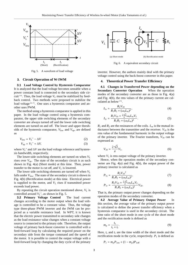
VLRLC
(a) Short mode
RL
Ia
VLC
(b) Rectification mode
Fig. 6. A equivalent secondary circuit
inverter. However, the authors mainly deal with the primaryvoltage control using the buck-boost converter in this paper.
4. Theoretical Power Transfer Efficiency
4.1 Changes in Transferred Power depending on theSecondary Converter Operation When the operationmodes of the secondary converter are as those in Fig. 4(a)and Fig. 4(b), the rms values of the primary current are cal-culated as below(15).
I1s ≃R2V10
R1R2 + (ω0Lm)2, (4)
I1r ≃R2V10 +
2√
2πω0LmVL
R1R2 + (ω0Lm)2. (5)
R1 andR2 are the resistances of the coils.Lm is the mutual in-ductance between the transmitter and the receiver.V10 is therms value of the fundamental harmonic in the output voltageof the primary inverter. The Fourier transform,V10 can beexpressed as
V10 =2√
2π
V1, (6)
whereV1 is rms output voltage of the primary inverter.Hence, when the operation modes of the secondary con-
verter are Fig. 4(a) and Fig. 4(b), the output power of theprimary inverter is calculated as
P1s ≃R2V10
2
R1R2 + (ω0Lm)2, (7)
P1r ≃R2V10 +
2√
2πω0LmVL
R1R2 + (ω0Lm)2V10. (8)
That is, the primary output power changes depending on theoperation modes of the secondary converter.
4.2 Average Value of Primary Output Power Inthis section, the average value of the primary output poweris calculated to define the power transfer efficiency when ahysteresis comparator is used in the secondary circuit. Thetime ratio of the short mode in one cycle of the short modeand the rectification mode is defined as
mp =ts
ts + tr. (9)
Here,ts and tr are the time width of the short mode and therectification mode in the cycle, respectively.P1 is defined as
P1 = mpP1on+ (1−mp)P1off
3

Maximizing Power Transfer Efficiency of Wireless In-wheel Motor (Gaku Yamamotoet al.)
Load voltage VL [V]
Prim
ary
side
vol
tage
V10
[V
]
96
90
94 93 92 91
95
0 100 200 300 400 5000
100
200
300
400
500
(a) PL = 200 W
Load voltage VL [V]
Prim
ary
side
vol
tage
V10
[V
]
96
90
9493
95
9291
0 100 200 300 400 5000
100
200
300
400
500
(b) PL = 1000 W
Load voltage VL [V]
Prim
ary
side
vol
tage
V10
[V
]
96
95
0 100 200 300 400 5000
100
200
300
400
500
(c) PL = 3300 W
Fig. 7. Transition of power efficiencyη with changing load powerPL
=R2V10
2 + 2√
2πω0Lm(1−mp)V10VL
R1R2 + (ω0Lm)2. (10)
4.3 Theoretical Formula of mp As shown in Fig. 3,the load power is defined asPL. The load resistanceRL is cal-culated by assuming that the load is regarded as a resistance.
RL =VL
2
PL(11)
Therefore, the secondary circuit is assumed to be Fig. 6(a)and Fig. 6(b), depending on the operation mode of the sec-ondary converter.
By solving the circuit equation in Fig. 6(a),VL is calculatedas
VL(t) = Vupexp
(− 1
RLCt
). (12)
Here, t= 0 is the time at whichVL is equal toVup. The sec-ondary circuit switches to Fig. 6(b) when t is equal totr, andV(tr) is equal toVlow at this point. Thus,tr is calculated asfollowing,
tr = RLCln
(Vup
Vlow
). (13)
Next, by solving the circuit equation in Fig. 6(b),VL is cal-culated as
VL(t) =RLIa+ (Vlow− RLIa)exp
(− 1
RLCt
). (14)
Here, t= 0 is the time at whichVL is equal toVlow. The sec-ondary circuit switches to Fig. 6(a) when t is equal tots, andV(ts) is equal toVup at this point. Thus,ts is calculated as thefollowing,
ts = RLCln
(Vlow − RLIa
Vup − RLIa
). (15)
In conclusion, the theoretical formula ofmp is
mp =
ln(
VlowVup
)ln
(VlowVup
)+ ln
( Vup+RL Ia
Vlow−RL Ia
) . (16)
The output current of the secondary converterIa in Fig. 6(b)is equals to the average value of the rectified current of thesecondary resonator in Fig. 4(b). The rms value of the sec-ondary resonator currentI2r is calculated as below.
I2r ≃ω0LmV10 − 2
√2π
R1VL
R1R2 + (ω0Lm)2(17)
Therefore, assuming thatI2r is a sinusoidal wave current,Ia
is calculated as
Ia =2√
2π
ω0LmV10 − 2√
2π
R1VL
R1R2 + (ω0Lm)2. (18)
4.4 Power Transfer Efficiency From Eq. (10), thepower transfer efficiency from a primary inverter output toa secondary converter is
η =R1R2 + (ω0Lm)2PL
R2V102 + 2
√2πω0Lm(1−mp)V10VL
. (19)
mp is regarded as a function ofV10 and VL from Eq. (11),Eq. (16) and Eq. (18). Thus,η is also regarded as a functionof V10 andVL from Eq. (19). Figure 7 shows the efficiencycalculated from Eq. (19) with changingV10 andVL in casePL are 200 W, 1000 W and 3300 W. In all cases, there arecombinations ofV10 andVL which maximize power transferefficiency.
The W-IWM cannot be driven if the desired value of theload voltage is not achieved when the secondary converter isoperated in rectification mode. Thus, the minimum primaryvoltageV1min to attain a certain load voltage is introduced byanalyzing the circuit assuming the secondary converter to bea full wave rectifier. It is calculated as
V1min =π
2√
2
8π2 R1RL + R1R2 + (ω0Lm)2
ω0LmRLVL. (20)
In Fig. 7, the white part indicates the range that cannot at-tain the required power in the secondary circuit. In this area,V1min > V10 is consisted.ω0Lm ≫ R1 ≃ R2 is obtained from the transmitter and re-
ceiver coils which are used in this paper. Thus,V1min can beexpressed as
V1min ≃π
2√
2ω0Lm
PL
VL. · · · · · · · · · · · · · · · · · · · · · · · · (21)
4

Maximizing Power Transfer Efficiency of Wireless In-wheel Motor (Gaku Yamamotoet al.)
load motorW-IWM
secondary coil
primary coiltorque meter
primary circuit
reduction gear integratedhub bearing unit
Fig. 8. An experimental bench measurement
218
mm
218
mm
350 mm 300 mm
primary coil secondary coil
Fig. 9. Coils for WPT
Table 2. Parameters of Resonator
Parameter Primary SecondaryCoil resistanceR1,2 0.411Ω 0.382ΩCoil inductanceL1,2 260µH 223µH
CapacitanceC1,2 13.5 nF 15.7 nFMutual inductanceLm 48.6µH (gap: 100 mm)Operating frequency 83.3 kHz
where first and second items in eq. (20) are ignored. There-fore, the boundary line ofV10 between the color and the whiteregions in Fig. 7 is inversely proportional toVL
5. Basic Experiment
5.1 Experimental Set The experimental set and theparameters of the resonator are shown in Fig. 8 and Tab. 2,respectively. Figure 9 shows the configuration of the coils,which are made by litz wires and ferrite(5). The rectifiedthree-phase 200 V AC is used instead of a battery as thepower source. The resonant frequency is 85 kHz, which isstated as the nominal frequency by the Society of Automo-tive Engineers (SAE)(16). Similarly to being mounted on anEV, the gap between the transmitter and the receiver is setto 100 mm. Switching elements in the primary inverter andthe secondary converter are SiC-MOSFETs(made by ROHM,BSM180D12P2C101)(17).
5.2 Comparison of Theoretical and Experimental Val-ues ofmp The theoretical values ofmp were compared tothe experimental values. In this experiment, the W-IWM hadbeen supplied with 30 % of the rated torque value while therevolution speed of the load motor was set to 68 rpm. Theoutput torque was 64 Nm, and the load powerPL was 562W. While changing primary voltage,mp was measured at thispoint. V∗L and∆V were set as 240 V and 2.5 V, respectively.Figure 10 shows the measurement result of the secondary res-onator voltage. The voltage becomes nearly zero when the
0 0.005 0.01 0.015 0.02-300
-200
-100
0
100
200
300
Time [s]
Seco
ndar
y vo
ltage
V2 [
V]
Short(ts)
Rectification(tr)
Fig. 10. A waveform of a secondary resonator
0 50 100 150 2000
0.2
0.4
0.6
0.8
1
Primary side voltage V10
[V]
mp [
-]
CalculationExperiment
Fig. 11. A comparison with theoretical and experimentvalue ofmp
lower-side switching elements of the secondary converter areturned on in Fig. 10. Thus,ts is this time width andtr is theother as shown in Fig. 10. The experimental value ofmp, cal-culated by Eq. (9) is defined as the average of ten periods. Onthe other hand, the theoretical value is calculated by Eq. (16).
Comparison of the theoretical and experimental values areshown in Fig. 11.V10 is calculated by Eq. (6) by measuringthe output voltage of the primary inverterV1. The W-IWMcannot be driven in the range wheremp is equals to zero be-causeV10 becomes lower thanV1min. Therefore, experimentswere not performed in this range. The validity of the theoret-ical formula is verified by the experiment.
5.3 Transition of Power Transfer Efficiency withchangingV10 Theoretical values ofη were compared tothe experimental values with the changingV10. In this ex-periment, the W-IWM was supplied with 10 % and 30 % ofthe rated torque value while the revolution speed of the loadmotor was set to 68 rpm. The output torque was 19 Nm and64 Nm, and the load powerPL was 188 W and 562 W, re-spectively. By changing the primary voltage, efficiency fromprimary inverter output to the secondary converter outputηwas measured at these points.V∗L and∆V were set as 240 Vand 2.5 V.
Comparison of the theoretical and experimental values areshown in Fig. 12. The theoretical value is calculated byeq. (19), but the losses of the secondary converter is ignoredin this formula. Thus, the experimental average efficiency ofthe secondary converter is multiplied by the theoretical valuein Fig. 12.
The theoretical primary voltage maximizing the transfer ef-ficiency agrees with the experimental value. The errors be-tween the calculation and the experiment are probably due tothe wiring inductance and resistance.
5

Maximizing Power Transfer Efficiency of Wireless In-wheel Motor (Gaku Yamamotoet al.)
50 75 100 125 15080
82.5
85
87.5
90
Primary side voltage V10
[V]
Eff
icie
ncy
[%]
CalculationExperiment
(a) T=10 % N= 68 rpm
80 100 120 14085
87.5
90
92.5
95
Primary side voltage V10
[V]E
ffic
ienc
y [%
]
CalculationExperiment
(b) T=30 % N= 68 rpm
Fig. 12. Power transfer efficiency with changingV1
225 250 275 300 325 350 37580
82.5
85
87.5
90
Load voltage VL [V]
Eff
icie
ncy
[%]
CalculationExperiment
(a) T=10 % N= 68 rpm
225 250 275 300 325 350 37585
87.5
90
92.5
95
Load voltage VL [V]
Eff
icie
ncy
[%]
CalculationExperiment
(b) T=30 % N= 68 rpm
Fig. 13. Power transfer efficiency with changingVL
5.4 Transition of Power Transfer Efficiency withchanging VL Theoretical values ofη were compared tothe experimental values with changingVL. In this exper-iment, the conditions of the motor output are the same ofSec. 5.3. By varying the load voltageVL from 240 V to 350V, in steps of 10 V, the efficiency from the primary inverteroutput to the secondary converter outputη was measured atthese points. The primary voltage is 85 V with 10 % torquecommand and 122 V in 30 % torque command. These voltagevalues are the points where the efficiency has the maximumin Fig. 12.
Comparison of the theoretical and experimental values areshown in Fig. 13. Similar to Seq. 5.3, the experimental av-erage efficiency of the secondary converter is multiplied bythe theoretical value in Fig. 13. The theoretical load voltagemaximizing the transfer efficiency agrees with experimentalvalue as well as Sec. 5.3.
6. Conclusion
In this paper, the outline of the Wireless In-Wheel Motorusing manetic resonance coupling is explained. In this sys-tem, a full bridge converter is used as the AC-DC converter inthe receiver circuit. For load voltage control, the upper-sideswitching elements of the converter are always turned off andthe lower-side switching elements are turned on and off. Thepower transfer efficiency in the system is demonstrated. It isrevealed that there is a combination of the primary and theload voltage which maximizes the efficiency. The effective-ness of the theoretical formula of the efficiency is also shown,according to the experiment performed with bench set. Thetheoretical primary and load voltage maximizing transfer ef-ficiency agrees with experimental value.
Future work includes the control of the primary and load
voltage maximizing the efficiency in real time.
Acknowledgment
The research presented in this paper was funded in partby the Ministry of Education, Culture, Sports, Science andTechnology grant (No. 26249061). The authors would like toexpress their deepest appreciation to the Murata Manufactur-ing Co., Ltd. for providing the laminated ceramic capacitors(U2J characteristics) used in these experiments.
References
( 1 ) Y. Hori: “Future Vehicle Driven by Electricity and Control Research on FourWheel Motored“UOT Electric March II””, IEEE Trans. IE, Vol. 51, No. 5,pp. 954–962 (2004)
( 2 ) M. Suzuki, K. Sakai, K. Okada, and Y. Makino: “Development of In-WheelMotor Type Axle Unit”, NTN TECHNICAL REVIEW, No75, pp. 46–52(2007) (in Japanese)
( 3 ) Ntn corporation, WO2013108546 A1 (2013)( 4 ) Toyota Motor Corporation, P2012-223041A (2012) (in Japanese)( 5 ) G. Yamamoto, T. Imura, H. Fujimoto: “Transmitting and Receiving Coil
Design for Wireless Power Transfer to In-Wheel Motor”, IEEJ, IIC-14-073/MEC14-061, pp. 103–108 (2014) (in Japanese)
( 6 ) D. Gunji, T. Imura, H. Fujimoto: “Fundamental Research of Power Conver-sion Circuit Control for Wireless In-Wheel Motor using Magnetic ResonanceCoupling”, IEEE IECON2014, 40th Annual Conference of the IEEE Indus-trial Electronics Society, pp. 3004–3009 (2014)
( 7 ) M. Sato, G. Yamamoto, D. Gunji, T. Imura, and H.Fujimoto: “Developmentof Wireless In-Wheel Motor based on Magnetic Resonance Coupling,” 2013JSAE Annual Congress (Autumn), No. 113-14, pp. 9–12 (2014) (in Japanese)
( 8 ) A. Kurs, A. Karalis, R. Moffatt, J. D. Joannopoulos, P. Fishe, and M. Soljacic:“Wireless Power Transfer via Strongly Coupled Magnetic Resonances”, inScience Express on 7 June 2007, Vol.317, No.5834, pp. 83–86 (2007)
( 9 ) T. Imura, H. Okabe, T. Uchida, and Y. Hori:“Wireless Power Transfer dur-ing Displacement Using Electromagnetic Coupling in Resonance “ Magnetic-versus Electric-Type Antennas” ”, IEEJ Trans. IA,Vol.130, No.1, pp. 76–83(2010) (in Japanese)
(10) K. Iimura, N. Hoshi, and J. Haruna:“Experimental Discussion on Induc-tive Type Contactless Power Transfer System with Boost or Buck ConverterConnected to Rectifier,” Power Electronics and Motion Control Conference(IPEMC), 2012 7th International, Vol. 4, pp. 2652–2657 (2012)
(11) M. Kato, T. Imura, and Y. Hori, “Study on Maximize Efficiency by SecondarySide Control Using DC-DC Converter in Wireless Power Transfer via Mag-netic resonant Coupling,” in IEEE EVS27 Internatonal Battery, Hybrid andFuel Cell Electric Vehicle Symposium (2013)
(12) W. Zhong, and S. Y. R. Hui:“Maximum Energy Efficiency Tracking for Wire-less Power Transfer Systems”, Power Electronics, IEEE Transactions on(2014)
(13) H. Fujimoto, T. Miyajima, and J. Amada: “Development of Electric Vehiclewith Variable Drive Unit System”, International Electric Vehicle TechnologyConference & Automotive Power Electronics Japan 2014 (2014)
(14) D. Gunji, T. Imura, and H. Fujimoto“Stability Analysis of Secondary LoadVoltage on Wireless Power Transfer using Magnetic Resonance Coupling forConstant Power Load”, IEE of Japan Industry Applications Society Confer-ence, No.3-42, pp.251–254 (2014) (in Japanese)
(15) D. Gunji, T. Imura, H. Fujimoto: “Basic Study of Transmitting Power ControlMethod without Signal Communication on Wireless Power Transfer”, IEEJ,SPC-14-153,HCA-14-061,VT-14-048 (2014) (in Japanese)
(16) SAE International: “Wireless charging advances with selection of 85-kHzcharging frequency”, http://articles.sae.org/12647/ (2013)
(17) ROHM: “SiC Power Module BSM180D12P2C101 Datasheet” (2013)
6