investigation of uniaxial asymmetric high-cycle fatigue
TRANSCRIPT

Investigation of Uniaxial Asymmetric High-cycle Fatigue Failure Behavior of 7075-T651 Aluminum Alloy Sheet
Da-Lian YANG1, a, Yi-Lun LIU1, 2, b*, Song-Bai LI1, c, Jiu-Huo YI1, d, Jie TAO1, e 1State Key Laboratory for High Performance and Complex Manufacturing, School of Mechanical and
Electrical Engineering, Central South University, Changsha 410083, China
2Light Alloy Research Institute, Central South University, Changsha 410083, China
[email protected], [email protected], c [email protected],[email protected], [email protected]
*Corresponding author
Keywords: 7075 Aluminum Alloy, High Cycle Fatigue (HCF), S-N Curve, Fatigue Fracture.
Abstract. In this investigation, the high cycle fatigue life of 7075-T651 aluminum sheets under
different stress levels were tested, and S-N curves were obtained by fitting the test data. For the
problem that the traditional S-N curve fitting methods without considering the effect of fatigue limit
on the S-N curve fitting accuracy, the traditional fitting methods were improved, the results show that
the improved method can reduce the fitting error. The high- cycle fatigue fracture morphology of
260MPa was observed by scanning electron microscopy (SEM). The observations reveal that the high
cycle fatigue fracture morphology shows ductile fracture features. The main reason of the crack
nucleation is that the second phase particles on the sub-surface, but the small dispersed precipitates
can improve the fatigue performances. The morphology of the fatigue crack propagation is “stair”
distribution. The fatigue crack transient beak region is characterized by the mixed-rupture
characteristics of quasi-cleavage and dimples.
Introduction
With the advantages of small density, high strength, good machinability and heat treatment performances, the aluminum alloy of 7075 are widely used in the fields of aerospace industry, transportation, electronic communication [1-2]. These components suffered from the external alternating loads inevitably in service, eventually, the materials of components appear the irreversible fatigue failure, and either affect the normal operation of the equipment, or causes a serious disaster. Therefore, it is very significance to further investigate the fatigue performances and the fatigue mechanism of the 7075 aluminum alloy so that it can provide a guide for the structural design to reduce the fatigue accidents.
In the past decade, many domestic and foreign scholars have done a lot of work on the fatigue performance investigation of aluminum alloy and have obtained a series of achievements. E. Cirik [3] investigated the effect of anodic oxidation on the fatigue performance of 7075-T6 alloy and fatigue tests with pre-corroded specimens showed that fatigue life of coated specimens was significantly affected by pre-corrosion, except for the specimen with the thickest coating layer. T. W. Zhao [4] tested the fatigue crack propagation rate of 7075-T651 aluminum alloy with the standard and non-standard compact specimens under the conditions of different stress ratio (R), overload, underload, high-low order, by improving the model of Wheeler [5], a good prediction results that the loading condition influence on the fatigue crack growth were obtained. R. S. Sachin [6] revealed the fretting fatigue behavior in 7075-T6 aluminum alloy use constant amplitude cyclic loading, using a Zeiss confocal microscope and a Hitachi Scanning Electron Microscope (SEM) to characterize the fretting fatigue damage, the results showed that fretting degradation depends on the microstructure of the material. J. Han [7] discovered the fatigue mechanism and fracture characteristics of the 7075-T651 aluminum alloy use the standard cylinder specimen, meanwhile, he obtained the fatigue life and S-N curve under different stress amplitudes.
Despite comprehensive work, many questions remain to be answered, the fatigue mechanism of
7075-T651 aluminum alloy based on the low cycle fatigue (LCF) testing and use the cylinder
International Conference on Material Science and Application (ICMSA 2015)
© 2015. The authors - Published by Atlantis Press 252

specimens usually, and there are less investigation of the fatigue performance of 7075-T651,
especially, the high-cycle fatigue (HCF) performance should be studied more in-depth. In the current
investigation, the fatigue performance often based on the medium thick sheet, but the fatigue
performance of the aluminum alloy sheet was less studied. In this investigation, high-cycle fatigue
experiments will be conducted using 7075-T651 aluminum alloy sheet under the conditions of
different stress amplitude load, so that it can provide a fatigue performance guide for the application
of 7075-T651 aluminum alloy.
Experimental
Material and Specimens
The material used in the current experimental investigation was 7075-T651 aluminum alloy sheets
which come from Europe (4mm thick). The chemical composition as shown in Table 1.
Tab. 1 Chemical composition of aluminum alloy 7075-T651 (wt. %)
Ti Mn Si Fe Cr Cu Mg Zn Al
0.019 0.034 0.06 0.17 0.18 1.5 2.45 5.71 Bal.
7075 aluminum alloy, in temper T651, is a kind of high strength aluminum alloy, widely used in
the aerospace industry, the ultimate tensile strength of longitude- trans-verse orientation (L-T) up to
587 MPa (85.82 ksi), the 0.2% offset yield strength of longitude- transverse orientation (L-T) up to
519 MPa (75.88 ksi) and the elongation is 13.0%. The 7075-T651 aluminum alloy sheets are detected
by X-ray detector and there are no obvious defects. The microstructure as shown in Fig. 1.
In this investigation, the uniaxial arc shaped sheet specimens, conforming to the specifications in
ASTM, were machined from a 7075- T651 aluminum alloy sheet, 4 mm (0.157 in.) thick, The stress
axes of the specimens were parallel (longitudinal) and perpendicular (transverse) to the rolling
direction, as shown in Fig. 2. The cutting method used the wire cutting technology in order to reduce
damage. Polished the machined surface of specimen with fine sandpaper uniformly in order to
minimize the stress concentration.
Fig. 1 The microstructure of 7075-T651 Fig. 2 The shape and the size of high cycle
aluminum alloy. fatigue specimen (unit: mm)
HCF Testing
Cyclic- stress- controlled high-cycle fatigue tests were performed on a fully-automated,
closed-loop servo hydraulic materials test system which was made by the United States MTS
company. This test system with a load cell which can provide the maximum static load 50kN and the
maximum dynamic load 30kN. The testing conforming to the specifications in ASTM. The
stress-controlled tests were conducted at room temperature (25°C), in the air, at a constant cyclic
frequency of 40 Hz and a stress ratio R=0. 1, the loading force changed according to the sine curve
and the maximum stress levels were 350MPa~140MPa. The whole test process was completed
automatically and the datum was recorded.
Twenty-one specimens were tested. Stopping the load if the cycles more than 107 because if the
cycles more than 107, it is generally considered that the specimen survives forever under the stress
L
T
S
253
level. The fatigue fracture morphology observation was performed on the scanning electron
microscope (TESCAN MORA3 LMU), the accelerating voltage was 20 KV, and the energy
dispersive spectrometry was conducted on the OXFORD instrument.
S-N Curve Fitting and Fatigue Limit Estimation
Usually, to ensure the fitting S-N curve can accurately describe the fatigue life properties of
material, a large amount of test datum is required, however, it is great expensive to obtain a large
amount of experimental datum in practice. Using the up and down method can obtain the fatigue limit
of material, but the higher the test accuracy desired, the greater the amount of tests required and the
higher the costs increased. If the fatigue limit is unknown, the fitting results of the traditional S-N
fitting method are different from the test data, especially, for higher cycle life, so, the fatigue limit
estimate by the S-N curve is different from the real value. To solve these problems, the traditional
S-N curve fitting method was improved, before fitting S-N curve, the fatigue limit was pre-estimated.
The details as follows:
For l stress levels2i lS S S , if the specimen failure under the stress level
iS and the cycle
number 710iN , but not failure under the stress level1iS and the cycle number 7
1 10iN , then it can
be estimated that the fatigue limit in the range ofiS to
1iS , and the test data
1 1{ , }i iS N cannot
participate SN curve fitting. Calculating:
^
1 1( ) / 2i i iS S S (1)
where ^
1iS is the pre-estimate fatigue limit and the cycle number^
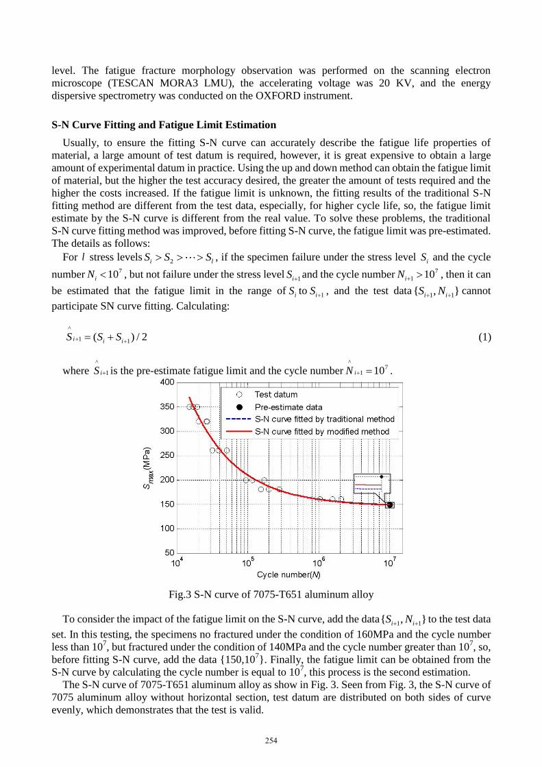
71 10iN .
Fig.3 S-N curve of 7075-T651 aluminum alloy
To consider the impact of the fatigue limit on the S-N curve, add the data1 1{ , }i iS N
to the test data
set. In this testing, the specimens no fractured under the condition of 160MPa and the cycle number
less than 107, but fractured under the condition of 140MPa and the cycle number greater than 10
7, so,
before fitting S-N curve, add the data {150,107}. Finally, the fatigue limit can be obtained from the
S-N curve by calculating the cycle number is equal to 107, this process is the second estimation.
The S-N curve of 7075-T651 aluminum alloy as show in Fig. 3. Seen from Fig. 3, the S-N curve of
7075 aluminum alloy without horizontal section, test datum are distributed on both sides of curve
evenly, which demonstrates that the test is valid.
254

It also can be seen from Fig.3 that the fatigue limit, which are estimated by S-N curve use the
modified data, are higher than use the test datum, and the fatigue limit, which are estimated use the
modified datum, is closer to the real fatigue limit which in the range of 140 MPa to 160 MPa. All
results show that the S-N curves fitted use the modified datum can describe the fatigue life of material
more accurate. Thereby, it can be estimated the fatigue limit is 149.0033MPa, which less slightly than
the pre-estimate fatigue limit.
Fatigue Fracture Morphology Observation
From the Macroscopic Scale
The fatigue fracture morphology of stress level 260 MPa was observed by SEM. The low
magnification SEM photographs are shown in Fig.4. Seen from the Fig.4 (a), there are three typical
regions: the fatigue crack initiation region (A), the fatigue crack propagation region (B) and the
fatigue transient break region (C), among them, the area of the fatigue transient break region is
largest.
The Ref [7] pointed out that for the specimens without internal tissue defects, the fatigue crack
often originated from sub-surface, in this investigation, the fatigue crack initiated from subsurface
too.
The main incentive of the fatigue crack initiation is that the resistance of surface is smaller and is
easier to form the local stress concentration, the material appear local plastic deformation under the
local high stress, because of the presence of large size precipitated phase particles in the alloy tissue
and their properties (strength, Young’s modulus) are different from the solute particles’, under the
action of cyclic load, either the surface of the precipitated phase particles and the solute tissue appear
to slide and separation, or the precipitated phase particles are brittle and fractured themselves, then
the cracks initialize on the weak point of the key regions, lastly, the cracks appear. Some micro cracks
merge into a large crack, and which propagate from the crack initiation region to material internal
along the direction of perpendicular load, then the fatigue crack propagation region is formed and the
radial pattern “stair” is left (Fig. 4 (b)). Finally, the fatigue crack transient beak region is formed while
the material unable to bear the external load and fracture.
Fig. 4 Fatigue fracture morphology of σmax=260MPa from macroscopic scale: (a) the panorama of the
fracture morphology; (b) the fatigue crack initiation morphology; (c), (d): the EDS spectrum
The EDS spectrum of the precipitated phase particles as shown in Fig.4 (c) and Fig.4 (d), it can be
seen that those precipitated phase particles are rich Fe intermetallic compounds which formed in the
solidification process (Fig.4 (c)) and others are silicon-containing compounds (Fig.4 (d)). Therefore,
reducing impurity in the high strength aluminum alloy in smelting process can greatly improve its
fatigue performance.
From the Microscopic Scale
The fatigue fracture morphology of stress level 260 MPa was observed by high magnification
SEM, as shown in Fig.5. The fatigue crack propagation region is shown in Fig.5 (a), the fatigue crack
growth region is a parallel serrated section, which is a typical shear fracture, there are plenty of
spherical holes surround the shear region, these holes were formed by undissolved phase debond from
the matrix under fatigue loading. The reason of this phenomenon is that there are a lot of nano
(a)
2mm
(b)
200μm
(c)
(d)
A B
C
255

strengthening phases in 7075 aluminum alloy (Fig. 5 (b)), which resisted the crack to propagate, the
cracks are difficult to propagate, which lead to appear large deformation on the adjacent border, thus,
the alloy fractured along the grain layer and the fracture appears small plane characteristics.
Fig. 5 Fatigue fracture morphology of σmax=260MPa from microscopic scale:(a) fatigue crack
morphology of propagation region; (b) Fatigue stripe; (c) Fatigue cracks morphology of the transient
breaking region
In the crack propagation region, the fatigue stripes are clear and the stripe intervals are equal and
about 0.3μm, as shown in Fig. 5 (c). It reveals that the crack propagation rate is stable, in addition,
there are many secondary cracks in the crack propagation region, which are propagated from the
surface to the internal and parallel to the fatigue stripes. There are both intergranular fracture and
transgranular fracture, in this investigation, the latter is mainly. The secondary cracks depth is much
greater than the depth of the fatigue stripes.
When the fatigue crack propagated to the critical dimension, the material become instability,
fractured immediately and the transient break region is formed. The transient break region has the
mixed-rupture characteristics of quasi-cleavage and dimples. The surface of the fracture has a large
number of torn edges and there are small equiaxial dimples on edge.
Conclusions
(1) The stress level has great influence on the fatigue life of the 7075-T651 aluminum alloy sheet.
The fatigue life of aluminum alloy 7075-T651 decreases with increases of the stress amplitude and
the S-N curve without horizontal section.
(2) The method can effectively improve the accuracy of the S-N curve, which provide a reference
method for S-N curve fitting. Fatigue limit was obtained by this method under test conditions and the
fatigue limit is149.0033MPa.
(3) The fatigue fracture macro observation revealed that the high-cycle fatigue fracture
morphology of 7075-T651 aluminum alloy sheet show ductile fracture features. The main reason of
the crack nucleation is that the second phase particles on the sub-surface, but the small and dispersed
precipitates have a positive impact on the alloy fatigue performances. The morphology of the fatigue
crack propagation is “stair” distribution. The fatigue crack transient beak region is characterized by
the mixed-rupture characteristics of quasi-cleavage and dimples.
Acknowledgement
This project is supported by the National Natural Science Foundation of China (51375500); Hunan
Provincial Education Department Funded Projects (2013SK2001); The Fundamental Research Funds
for the Central Universities of Central South University (2013zzts037), are gratefully acknowledged.
References
[1]Z. T. Wang, R .Z. Tian, Aluminum Processing Handbook, Central South University Press,
Changsha, 1988.
(a)
20μm
(b)
2μm 20μm
(c)
256

[2]B. Liu, C. Q. Peng, R. C. Wang, et al., Recent development and prospects for giant plane
aluminum alloys, The Chinese Journal of Nonferrous Metals. 9(2010) 1705-1715.
[3]E. Cirik, K. Genel, Effect of anodic oxidation on fatigue performance of 7075-T6 alloy, Surface &
Coatings Technology. 21 (2008) 5190-5201.
[4]T. W. Zhao, J. X. Zhang, Y. Y. Jiang, A study of fatigue crack growth of 7075-T651 aluminum
alloy, International Journal of Fatigue. 30 (2008) 1169–1180.
[5]K. Walker, The effect of stress ratio during crack propagation and fatigue for 2024-T3 and
7075-T6 aluminum, Effects of environment and complex load history on fatigue life, ASTM STP.
462(1970) 1-14.
[6]R. S. Sachin, W. H. David, Fretting fatigue behavior in 7075-T6 aluminum alloy, Wear 261.
(2006) 426-434.
[7]J. Han, Q. X. Dai, Y. T. Zhao, et al., Study on Fatigue Performance of 7075 -T651 Aluminum
Alloys, Journal of Aeronautical Materials.4 (2010): 92-96.
257