investigation of torsion, warping and distortion of large ... · pdf fileinvestigation of...
TRANSCRIPT
Ocean Systems Engineering, Vol. 1, No. 1 (2011) 73-93 73
Investigation of torsion, warping anddistortion of large container ships
Ivo Senjanovi *, Nikola Vladimir and Marko Tomi
Faculty of Mechanical Engineering and Naval Architecture, University of Zagreb,
I. Lu i a 5, 10000 Zagreb, Croatia
(Received January 26, 2011, Accepted March 11, 2011)
Abstract. Large deck openings of ultra large container ships reduce their torsional stiffness considerablyand hydroelastic analysis for reliable structural design becomes an imperative. In the early design stagethe beam model coupled with 3D hydrodynamic model is a rational choice. The modal superpositionmethod is ordinary used for solving this complex problem. The advanced thin-walled girder theory, withshear influence on both bending and torsion, is applied for calculation of dry natural modes. It is shownthat relatively short engine room structure of large container ships behaves as the open hold structure withincreased torsional stiffness due to deck effect. Warping discontinuity at the joint of the closed and opensegments is compensated by induced distortion. The effective torsional stiffness parameters based on anenergy balance approach are determined. Estimation of distortion of transverse bulkheads, as a result oftorsion and warping, is given. The procedure is illustrated in the case of a ship-like pontoon and checkedby 3D FEM analysis. The obtained results encourage incorporation of the modified beam model of theshort engine room structure in general beam model of ship hull for the need of hydroelastic analysis,where only the first few natural modes are of interest.
Keywords: container ship; engine room; torsion; warping; distortion; analytics; FEM.
1. Introduction
In spite of the fact that ship hydroelastic behaviour is known for many years (Bishop and Price
1979), nowadays it is becoming more actual problem related to large container ships (Payer 2001,
RINA 2006). These ships are especially sensitive to torsion due to large deck openings and
conventional strength analysis based on the rigid body wave load is not reliable enough (Valsgård et
al. 1995, Shi et al. 2005). In the early design stage, when ship structure is not yet determined in
details, use of the beam model of hull girder for coupling with 3D hydrodynamic model, is
preferable (Malenica et al. 2007).
The modal superposition method is usually used for hydroelastic analysis and the beam structural
model has to describe the ship hull dry natural modes successfully. The natural modes are input data
for determining modal structural stiffness, restoring stiffness, hydrodynamic coefficients and wave
load (Tomaševi 2007).
The transverse bulkheads in large container ships are quite robust in order to increase torsional
stiffness and reduce distortion of cross-section. Height of their girders and stools is equal to the
có có
c
Ô
có
có
*Corresponding author, Professor, E-mail: [email protected]

74 Ivo Senjanovi , Nikola Vladimir and Marko Tomicó có
frame spacing, i.e., ca. 2 m. Due to larger number of bulkheads their influence can be taken into
account by increasing value of St. Venant torsional stiffness proportionally to the bulkhead strain
energy and of the corresponding open hull portion strain energy (Senjanovi et al. 2008).
Stiffness of the short engine room structure is reduced, that makes another problem related to
large container ships. Its complex deformation is illustrated in the case of a 7800 TEU container
ship, Fig. 1. The deck in-plane shear deformation is dominant, as well as bending of the stool on
the top of the transverse bulkheads. The engine room front and aft bulkhead are less skewed than
the hold bulkheads. Warping of the transom is very small, that is an important fact when specifying
boundary conditions for torsional vibrations of beam model.
Main problem related to beam model of container ship is to satisfy warping compatibility at the
joint of the closed engine room structure with the open hold cross-section. A sophisticate solution,
assuming that the cross-section discontinuity is compensated with the induced horizontal bending, is
presented in (Pedersen 1983, 1985). That solution is realistic for joint of long open and closed segments
of ship hull. However, in the considered case of the short engine room structure, 3D FEM analysis
shows that discontinuity at joint with open holds is compensated with distortion of cross-sections.
This paper aims to determine the effective values of stiffness parameters of short engine room
structure in the beam model, based on energy approach. Due to small aspect ratio, length/breadth,
the engine room structure behaves as the open hold structure with increased torsional stiffness.
Therefore, torsionally induced horizontal bending is small and can be neglected, which makes the
determination of the effective values of torsional stiffness parameters much easier (Senjanovi et al.
2010). In addition, distortion of the engine room transverse bulkheads is considered based on known
torsional and warping response. The basic formulae of thin-walled girder theory are used and the
procedure is verified by a 3D FEM analysis of ship-like pontoon.
2. Basic formulae for beam torsion
The torsional thin-walled girder theory is based on the assumption that the structure behaves as a
có
có
Fig. 1 Bird's eye view of the 7800 TEU container ship aftbody, the 2nd natural mode
Investigation of torsion, warping and distortion of large container ships 75
membrane and that there is no distortion of cross-section (Vlasov 1961, Haslum and Tonnesen
1972, Steneroth and Ulfvarson 1976). In the advanced torsional beam theory, shear influence on
torsion is taken into account in a similar manner to that in the flexural beam theory (Pavazza 2005).
Hence, twist angle consists of a pure twist angle and a shear contribution
(1)
where the latter depends on the former
(2)
E and G are Young's modulus and shear modulus, respectively, and Iw and Is are the warping
modulus and the shear moment of inertia of cross-section, respectively (Senjanovi et al. 2009).
The sectional forces include torque T, consisted of pure torque Tt and warping contribution Tw,
and bimoment Bw, as a result of the primary and secondary shear stress fields, and normal stress
due to restrained warping (Senjanovi et al. 2009)
, (3)
(4)
(5)
where It is the torsional modulus.
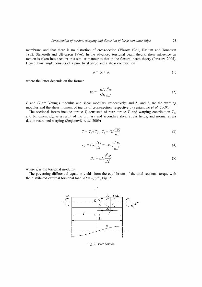
The governing differential equation yields from the equilibrium of the total sectional torque with
the distributed external torsional load, dT = −µxdx, Fig. 2
ψ ψt ψs+=
ψs
EIw
GIs--------
d2ψt
dx2
----------–=
có
có
T Tt Tw+= Tt GItdψt
dx--------=
Tw GIsdψs
dx--------- EIw
d3ψt
dx3
----------–= =
Bw EIwd2ψt
dx2
----------=
Fig. 2 Beam torsion

76 Ivo Senjanovi , Nikola Vladimir and Marko Tomicó có
(6)
Its solution reads
(7)
where
(8)
and ψp is a particular solution. The total twist angle (1) takes form
(9)
Now, it is possible to determine sectional forces by Eqs. (3), (4) and (5). The axial displacement
and normal stress read, respectively
, (10)
where w is the warping function.
3. Torsional stiffness of the engine room structure
Up to now the problem is considered assuming that there is no distortion of the cross-section.
Discontinuities of the hull beam due to both deck stool and wide deck strip are analysed in
(Pedersen 1983, 1985). The bending and shear effects of the stool are included in the equilibrium of
the bimoments as a discontinuity. The shear and normal stress distribution of a wide deck strip
acting on the hull beam contributes to the generalized hull sectional forces, i.e., bimoment,
transverse shear force, torsional moment and horizontal bending moment. Hence, a pure torsional
load induces horizontal bending, and the distributed sectional forces are incorporated into the
mathematical model through the governing equilibrium differential equation.
In the case of a short engine room, torsion induces distortion, while bending is negligible and this
complex problem is solved here by the energy balance approach and by applying the concept of
effective stiffness for reasons of simplicity. A closed hull segment is considered as an open one with
deck influence. For this purpose the deck strain energy is determined as follows.
The upper deck is exposed to large deformation, while the double bottom in-plane deformation is
quite small, Fig. 1. The relative axial displacement of the internal upper deck boundaries, with
respect to the double bottom, is a result of their warping, Fig. 3
(11)
EIwd4ψt
dx4
---------- GItd2ψt
dx2
----------– µx=
ψt A0 A1
x
l-- A2chαx A3shαx ψp+ + + +=
αGIt
EIw--------=
ψ A0 Al
x
l-- A2 1
It
Is---–⎝ ⎠
⎛ ⎞chαx A3 1It
Is---–⎝ ⎠
⎛ ⎞shαx ψp
EIw
GIs--------ψp
″–+ + + +=
u wψt′= σ Ewψt
″=
U UD UB+ wD wB+( )ψt
′= =

Investigation of torsion, warping and distortion of large container ships 77
This causes deck in-plane deformation and the problem can be solved in an approximate analytical
way by considering the deck as a beam. Its horizontal anti-symmetric deflection consists of pure
bending and shear contribution, Fig. 3. The former is assumed in the form
(12)
which satisfies the relevant boundary conditions: and , where Ub is the
boundary bending deflection. Shear deflection depends on the bending deflection (12)
(13)
where the internal deck cross-section area, A = 2at1, its moment of inertia, , and the
relation , are taken into account, Fig. 3. Total deflection is obtained by summing up
Eqs. (12) and (13), i.e., . The relation between the total boundary deflection and the
bending boundary deflection reads
(14)
The total internal deck strain energy consists of the bending and shear contributions
(15)
By substituting Eqs. (12) and (13) into (15), one finds
ub
y
2b------ 3
y
b---⎝ ⎠⎛ ⎞
2
– Ub=
ub 0( ) 0= ub
″0( ) 0=
us
EI
GA--------–
d2ub
dy2
---------- 2 1 v+( )a
b---⎝ ⎠⎛ ⎞
2y
b---Ub= =
I2
3---a
3t1=
E 2 1 v+( )G=
u ub us+=
U 1 2 1 v+( )a
b---⎝ ⎠⎛ ⎞
2
+ Ub=
E1
1
2---EI
d2ub
dy2
----------⎝ ⎠⎜ ⎟⎛ ⎞
2
dy
b–
b
∫1
2---GA
dus
dy-------⎝ ⎠⎛ ⎞
2
dy
b–
b
∫+=
Fig. 3 Upper deck deformation and double bottom rotation, (a) bird's eye view, (b) lateral view

78 Ivo Senjanovi , Nikola Vladimir and Marko Tomicó có
(16)
Finally, by taking into account Eqs. (11) and (14), yields
(17)
On the other hand, the total energy of the closed hull segment can be obtained by summing up the
warping and twisting strain energy of the open segment, marked as ( ), the deck strain energy and
work of distributed torque, i.e.,
(18)
where
(19)
(20)
(21)
Strain energy of the transverse bulkheads is not taken into account since it is quite small comparing
to above ones. Within a short span 2a, the constant value of (as for the deck) can be assumed,
so that Eq. (20), by inserting from Eq. (3), leads to
(22)
Furthermore, and in (18) can be contracted in one term since both depend on
(23)
where
, (24 (a), (b))
is the effective torsional modulus which includes both open cross-section and deck effects.
The engine room structure is designed in such a way that the hold double skin continuity is
ensured and necessary decks are inserted between the double skins. Eq. (17) for the strain energy is
E1 4 1 v+( )Gt1a
b---⎝ ⎠⎛ ⎞
3
1 2 1 v+( )a
b---⎝ ⎠⎛ ⎞
2
+ Ub
2=
E1
4 1 v+( )Gt1a
b---⎝ ⎠⎛ ⎞
3
1 2 1 v+( )a
b---⎝ ⎠⎛ ⎞
2
+
-------------------------------------- wD wB+( )2ψt
′2=
°
Etot
*Ew
°Et
°E1 Eµ–+ +=
Ew
° 1
2--- Bw
°ψt
″xd
a–
a
∫=
Et
° 1
2--- Tt
°ψt
′xd
a–
a
∫=
Eµ µxψ xd
a–
a
∫=
ψt
′
Tt
°
Et
°GIt
°aψt
′2=
Et
°E1 ψt
′2
Et
°E1+ GaItψt
′2=
It 1 C+( )It°
= CE1
Et
°-----=
It

Investigation of torsion, warping and distortion of large container ships 79
derived for the first (main) deck, and for the others it can be assumed that their strain energy is
proportional to the deck plating volume, V, and linearly increasing deformation with the deck
distance from the inner bottom, h, Fig. 3, since the double bottom is much stiffer than the decks. In
this way, the coefficient C, Eq. (24(b)), by employing (17) and (22), reads
(25)
where
. (26)
The general expressions for a thin-walled girder, Section 2, are still applicable for a closed
segment but with the effective stiffness moduli , and instead of the actual ones , and
. The above theory is elaborated in details in (Senjanovi et al. 2010).
4. Distortion of segmented pontoon
Open and closed cross-section segments are connected at the transverse bulkhead, which is
subjected to distortion due to different shear flows on its front and back side, induced by the torque
Mt, Fig. 4. Shear flow of the open cross-section, , is parabolic, while that of the closed cross-
section, , is uniform. The resulting side forces are , and the deck and bottom forces
read and , since for open section and due to self equilibrium for
given bottom flow , Fig. 4. The above shear forces satisfy the static equilibrium conditions. The
internal stress equilibrium leads to distortion of transverse bulkhead, δ.
CEi∑
Et
°-----------
4 1 v+( )t1a
b---⎝ ⎠⎛ ⎞
3
wD wB+( )2k
1 2 1 v+( )a
b---⎝ ⎠⎛ ⎞
2
+ It°a
-------------------------------------------------------------------= =
kVi
V1
-----hi
h1
-----⎝ ⎠⎛ ⎞
2
∑=
It Iw°
Is°
It*
Iw*
Is*
có
s°
s*
SS SS
°SS
*–=
SD SD
*= SB SB
*= SD
° 0= SB
°0=
s°
Fig. 4 Bulkhead shear forces at joint of open and closed cross-section segments

80 Ivo Senjanovi , Nikola Vladimir and Marko Tomicó có
Shear flows shown in Fig. 4 are realistic for long open and closed pontoon segments. However, in
the case of short closed segment, as engine room structure, the deck stiffness is reduced and its
shear flow is expected to be considerably reduced, Fig. 5. As a result the remained part of cross-
section behaves similarly to open one. Difference of the shear flows, , is quite small but still
causes bulkhead distortion, δ, which can be estimated in the following way.
Tendency of deck and double bottom of engine room structure subjected to torsion is rotation
around vertical axis in opposite directions due to warping of cross-sections, Fig. 6. The total
s° s*–
Fig. 6 Deck and bulkhead displacements and in-plane deformations, (a) bird's eye view on the deck, (b) axialview on the transverse bulkhead.
Fig. 5 Shear forces at joint of long open and short closed cross-section segments (qualitative presentation)
Investigation of torsion, warping and distortion of large container ships 81
transverse gap between the deck corner and the undeformed bulkhead top, i.e., inner bottom, yields,
Fig. 6
(27)
where relative axial deck displacement, due to both bending and shear, with respect to double
bottom, U, is given by Eq. (11). Gap V is cancelled by the deck corner transverse displacement vD
and the bulkhead top displacement vBH in opposite directions, as a result of equilibrated internal
shear forces SD and SBH, Fig. 6. The shear forces depend on shear deformations γD = vD / a and
δ BH = vBH /H', respectively, where δBH is distortional angle, Fig. 6. Thus, one can write for the deck
shear force
(28)
where t1 is the upper deck thickness, while k takes contribution of all decks to the resulting deck
force SD into account. It is obtained by assuming proportional increase of deck shear deformation
with deck distance from the inner bottom, and moment equilibrium of shear forced Si and SD. That
gives the same definition of k as that estimated by energy balance, Eq. (26).
In the similar way, the bulkhead shear force reads
(29)
The force equilibrium leads to the ratio of the deck and bulkhead transverse displacements
(30)
which is reciprocal to their stiffnesses. On the other hand, vD + vBH = V and by taking Eqs. (11), (27)
and (30) into account, one obtains
(31)
If the bulkhead thickness increases, tBH, the distortion angle decreases, and vice versa.
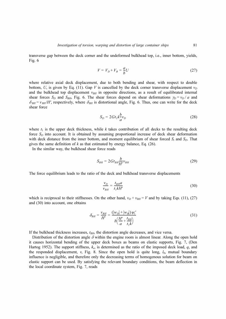
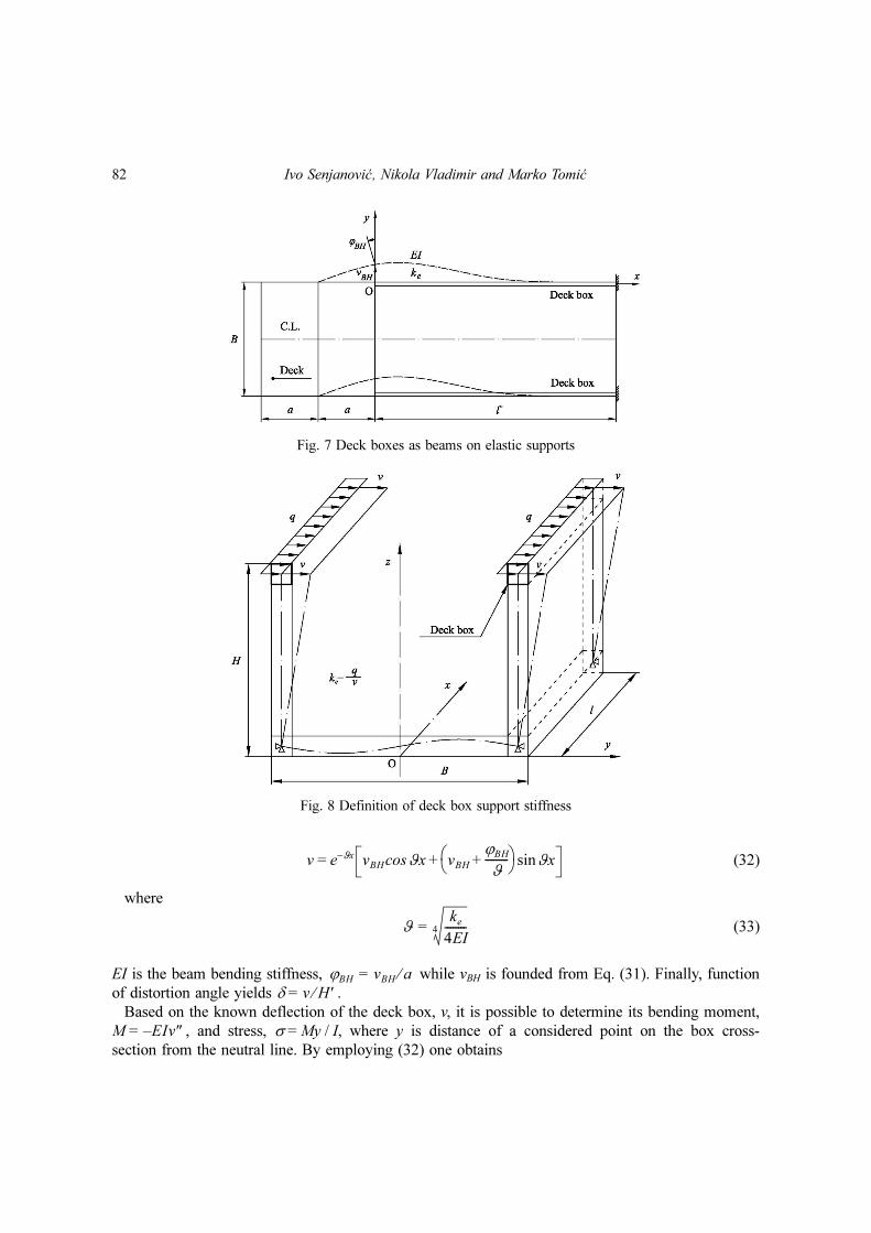
Distribution of the distortion angle δ within the engine room is almost linear. Along the open hold
it causes horizontal bending of the upper deck boxes as beams on elastic supports, Fig. 7, (Den
Hartog 1952). The support stiffness, ke, is determined as the ratio of the imposed deck load, q, and
the responded displacement, v, Fig. 8. Since the open hold is quite long, l0, mutual boundary
influence is negligible, and therefore only the decreasing terms of homogenous solution for beam on
elastic support can be used. By satisfying the relevant boundary conditions, the beam deflection in
the local coordinate system, Fig. 7, reads
V VD VB+a
b---U= =
SD 2Gt1kb
a---vD=
SBH 2GtBHb
H′------vBH=
vD
vBH
--------tBHa
t1kH′------------=
δBHvBH
H′--------
wD wB+( )ψt′
bH′a
------tBH
t1k-------+⎝ ⎠
⎛ ⎞-----------------------------------= =
82 Ivo Senjanovi , Nikola Vladimir and Marko Tomicó có
v = e−ϑx (32)
where
(33)
EI is the beam bending stiffness, while vBH is founded from Eq. (31). Finally, function
of distortion angle yields δ = .
Based on the known deflection of the deck box, v, it is possible to determine its bending moment,
M = , and stress, σ = My / I, where y is distance of a considered point on the box cross-
section from the neutral line. By employing (32) one obtains
vBH ϑxcos vBH
ϕBH
ϑ---------+⎝ ⎠
⎛ ⎞ ϑxsin+
ϑke
4EI--------4=
ϕBH vBH a⁄=
v H′⁄
EIv″–
Fig. 8 Definition of deck box support stiffness
Fig. 7 Deck boxes as beams on elastic supports
Investigation of torsion, warping and distortion of large container ships 83
(34)
The complete stress consists of the membrane part due to restrained warping, Eq. (10), and the
above bending stress, Eq. (34).
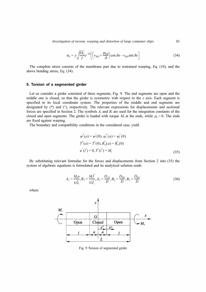
5. Torsion of a segmented girder
Let us consider a girder consisted of three segments, Fig. 9. The end segments are open and the
middle one is closed, so that the girder is symmetric with respect to the z axis. Each segment is
specified in its local coordinate system. The properties of the middle and end segments are
designated by (*) and (°), respectively. The relevant expressions for displacements and sectional
forces are specified in Section 2. The symbols Ai and Bi are used for the integration constants of the
closed and open segments. The girder is loaded with torque Mt at the ends, while µx = 0. The ends
are fixed against warping.
The boundary and compatibility conditions in the considered case, yield
(35)
By substituting relevant formulae for the forces and displacements from Section 2 into (35) the
system of algebraic equations is formulated and its analytical solution reads
(36)
where
σb yEke
I--------e
ϑx–vBH
ϕBH
ϑ---------+⎝ ⎠
⎛ ⎞ ϑxcos vBH ϑxsin–=
ψ*
a( ) ψ°
0( )= ψt
*′a( ) ψt
°′0( )=,
T*
a( ) T°
0( )= Bw
*a( ) Bw
°0( )=,
u°
l°( ) 0= T
°l°( ) Mt=,
A1
Mta
GIt
---------= B1
Mtl°
GIt°
---------= A3
DA3
D--------= B2
DB2
D--------= B3
DB3
D--------=, , , ,
Fig. 9 Torsion of segmented girder

84 Ivo Senjanovi , Nikola Vladimir and Marko Tomicó có
(37)
Value of constants A0, A2 and B0 is zero.
6. Geometric properties of a ship-like pontoon
A 7800 TEU Container Vessel of the following main particulars is considered:
Length overall Loa = 334 m
Length between perpendiculars Lpp = 319 m
Breadth B = 42.8 m
Depth H = 24.6 m
Draught T = 14.5 m
Displacement ∆ = 135530 t.
The material properties are the following:
Young's modulus E = 2.06 · 108 kN/m2
Shear modulus G = 0.7923 · 108 kN/m2
Poisson's ratio ν = 0.3.
The ship lateral plan and midship section are shown in (Senjanovi et al. 2008). The engine room
is located ca. 0.2 L from the aft perpendicular, where the cross-section is reduced. However, in this
numerical investigation, the engine room is extended to the full midship section so that a prismatic
ship-like pontoon can be created and analysed.
The geometrical properties of the open and closed ship cross-section are determined by the
program STIFF (1990) based on the strip theory of thin-walled girders (Senjanovi and Fan 1992,
1993), Table 1. It is evident that the cross-section area of the closed section is 50% larger than that
of the open section. The torsional modulus of the closed section is much higher than that of the
open section. The shear centre of the closed section is in the middle of the cross-section, while that
of the open section is below the keel.
The warping function of the open cross-section, w, is shown in (Senjanovi et al. 2009). The
relative axial displacement of the inside point of the upper deck and bilge, at the level of the inner
bottom, as the representative quantities, reads wD = -221 m2 and wB = 267 m2, respectively. The
relative moment of inertia of the decks volume k, Eq. (26), is calculated in Table 2.
DA3
Mt
G------ 1
It°
It---–⎝ ⎠
⎛ ⎞chβ l°
1–=
DB2
Mt
G------– shαa 1
It
It°
---–⎝ ⎠⎛ ⎞chβ l
° It
It°
---+=
DB3
Mt
G------ 1
It
It°
---–⎝ ⎠⎛ ⎞shαa shβ l
° α
β---chαa+=
D It°αchαa chβ l
°Itβshαa shβ l
°+=
có
có
có

Investigation of torsion, warping and distortion of large container ships 85
7. Pontoon torsion and distortion
Torsion of the segmented pontoon of the total length of L = 300 m is analysed according to the theory
presented in the previous Sections. Warping at the boundaries is restrained according to Fig. 1. Torsional
moment Mt = 40570 kNm is imposed on the pontoon ends. The following values of the basic parameters
are used: a = 10.1 m, b = 19.17 m, t1 = 0.01645 m, wD = −221 m2, wB = 267 m2, m4, Table 1,
k = 1.894, Table 2. As a result C = 22.42, Eq. (25), and accordingly m4, Eq. (24(a)), are
obtained. Since , effect of the short engine room structure on its torsional stiffness is obvious.
The obtained pontoon deformation functions ψ and are shown in Fig. 10. Distribution of
distortion angle, δ, is also included in Fig. 10. It is determined by employing the procedure described
in Section 4 with the following input data: rad/m, m, m,
tBH = 0.01131 m in Eq. (31); moment of inertia of deck box cross-section I = 0.711 m4, Fig. 11, stiffness
of elastic support ke = 721 kN/m2. Value of ke is obtained by FEM for a pontoon open segment.
8. FEM analysis
In order to verify the numerical procedure for torsional analysis by the beam model with effective
It°
14.45=
It 338.4=
It 0.36It*
=
ψt′
ψt′ 5.454 106–⋅= H′ 22.6= t1 0.01645=
Table 1 Geometrical properties of ship cross-sections
Quantity Symbol, unit Open section (°) Closed section (*)
Cross-section area A, m2 6.394 10.200
Horizontal shear area Ash, m2 1.015 2.959
Vertical shear area Asv, m2 1.314 2.094
Vertical position of neutral line zNL, m 11.66 13.96
Vertical position of shear centre zSC, m -13.50 9.60
Horizontal moment of inertia Ibh, m4 1899 2331
Vertical moment of inertia Ibv, m4 676 889
Torsional modulus It, m4 14.45 939.5
Warping modulus Iw, m6 171400 24010
Shear moment of inertia Is, m4 710.5 173.6
Table 2 Relative moment of inertia of deck structure volume
Item i Substructure Vi (m3) hi (m)
1 Upper deck 12.738 22.6 1
2 Deck 2 14.038 18.234 0.7174
3 Deck 3 8.955 10.422 0.1495
4 Deck 4 6.434 5.214 0.0269
k = 1.894
Vi
V1
-----hi
h1
-----⎝ ⎠⎛ ⎞
2

86 Ivo Senjanovi , Nikola Vladimir and Marko Tomicó có
stiffness parameters, designated as (1+2)D for short, 3D FEM models of the segmented pontoon are
created using software SESAM (2007). The superelement technique and shell element are used. The
pontoon ends are closed with transverse bulkheads. The pontoon is loaded at its ends with the
vertical distributed forces in the opposite directions, generating total torque Mt = 40570 kNm. The
midship section is fixed against transverse and vertical displacements, and the pontoon ends are
constrained against axial displacements (warping).
The lateral and bird's eye views on the deformed segmented pontoon are shown in Fig. 12, and
influence of the stiffer engine room structure is evident. Detailed view of this pontoon portion is
presented in Fig. 13. It is apparent that the double bottom and sides rotate around the vertical axis
as a “rigid body”, while the decks and transverse bulkheads are exposed to shear deformation. The
Fig. 10 Deformation functions of segmented pontoon
Fig. 11 Cross-section of deck box girders

Investigation of torsion, warping and distortion of large container ships 87
shear stress distribution in the front engine room bulkhead is shown in Fig. 14. The boundary
stresses, which cause distortion of cross-sections, are presented in Fig. 15. The assumed shear forces
in theoretical consideration of distortion, Fig. 5, are similar to the actual boundary shear stress
distribution in Fig. 15.
Fig. 12 Deformation of segmented pontoon, lateral and bird's eye view
Fig. 13 Lateral, axial, bird's eye and fish views on deformed engine room superelement

88 Ivo Senjanovi , Nikola Vladimir and Marko Tomicó có
9. Comparative analysis
Twist angles of the analytical beam solution, ψ(1+2)D, and that of FEM analysis, ψ3D, for the pontoon
bottom and side are compared in Fig. 16. As it can be noticed, there are some small discrepancies
between ψ(1+2)D,bottom and ψ3D,bottom, which are reduced to a negligible value at the pontoon ends
x = L/2:ψ 1 2+( )D bottom,
ψ3D bottom,
------------------------------0.000733153
0.000731985------------------------------- 1.0016= =
Fig. 14 Shear stresses in front engine room bulkhead
Fig. 15 Shear stresses at internal boundary of front engine room bulkhead

Investigation of torsion, warping and distortion of large container ships 89
The distortion of (1+2)D solution, δ(1+2)D = ψ(1+2)D,side − ψ(1+2)D,bottom, also follows quite well that of
3D FEM analysis, Fig. 16.
Warping of cross-section is evaluated by comparing axial displacements of the bilge and upper
deck as representative points, Fig. 17. Correlation of the results obtained by the beam theory and
FEM analysis is quite good from engineering point of view. There are some discrepancies between
axial displacements at the deck level in the engine room area as a result of large shear deformation,
Fig. 13. However, this is a local phenomenon, which can not easily be captured by the beam theory.
In order to have better insight into the structure deformation, the longitudinal distribution of the
vertical position of twist centre is shown in Fig. 18. The twist centre is the corrected position of the
shear centre due to shear influence on torsion, (Pavazza 2005, Senjanovi et al. 2009). Its value is
somewhat reduced in the engine room area, but it is still too far from the twist centre of the closed
có
Fig. 16 Twist angles of segmented pontoon
Fig. 17 Axial displacements of deck and bottom

90 Ivo Senjanovi , Nikola Vladimir and Marko Tomicó có
segment, which would induce considerable horizontal bending. Based on the above facts, the
introduced assumption of short engine room structure behaving as the open one with increased
torsional stiffness is acceptable.
Deformation of the joint cross-section is shown in Fig. 19, where position of shear and twist
centres for open and closed cross-sections are indicated, and compared with the position of twist
centre for the real 3D structure. Also, twist angles, ψ3D and ψ(1+2)D, and distortion angle, δ, which
are of the same order of magnitude, are drawn.
Longitudinal distribution of the axial normal stresses at the deck inside and outside point as well
Fig. 18 Vertical position of twist centre
Fig. 19 Twist and distortion angles of joint cross-section of open and closed segments
Investigation of torsion, warping and distortion of large container ships 91
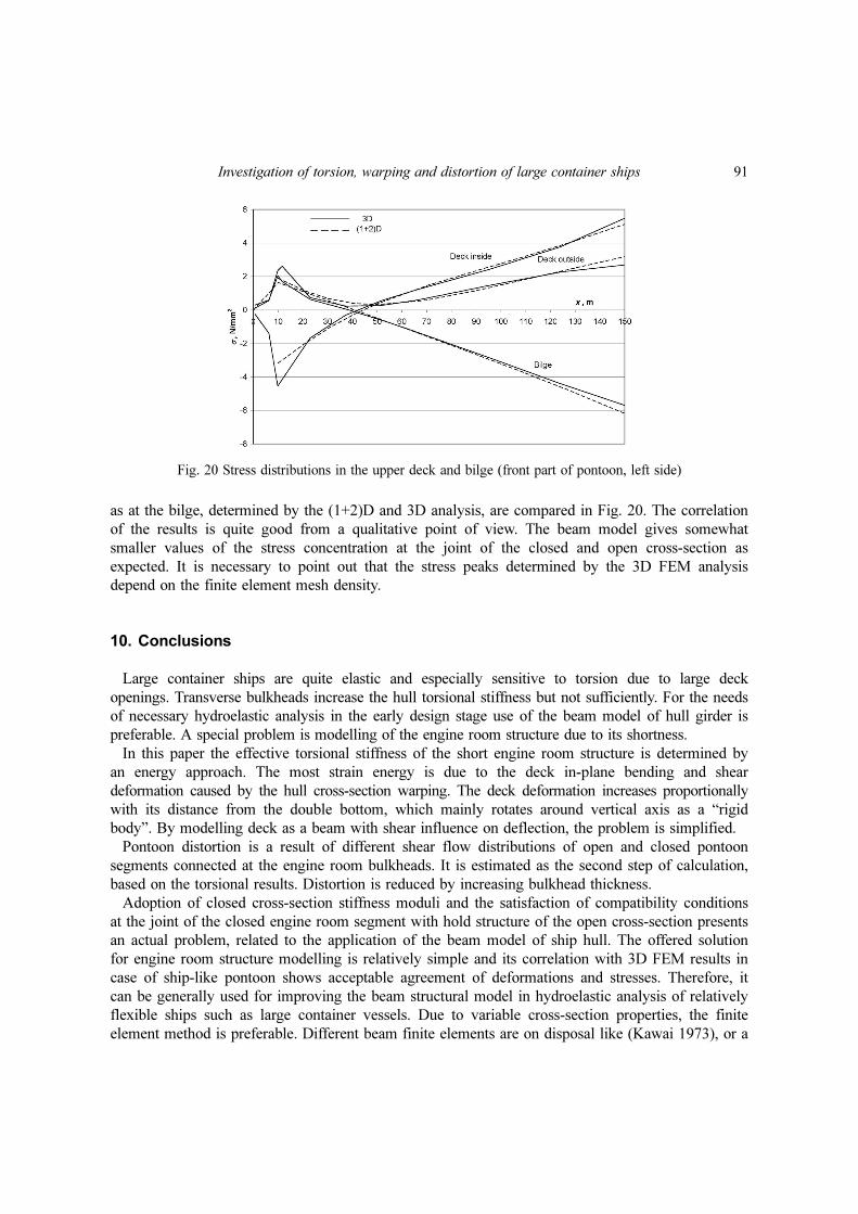
as at the bilge, determined by the (1+2)D and 3D analysis, are compared in Fig. 20. The correlation
of the results is quite good from a qualitative point of view. The beam model gives somewhat
smaller values of the stress concentration at the joint of the closed and open cross-section as
expected. It is necessary to point out that the stress peaks determined by the 3D FEM analysis
depend on the finite element mesh density.
10. Conclusions
Large container ships are quite elastic and especially sensitive to torsion due to large deck
openings. Transverse bulkheads increase the hull torsional stiffness but not sufficiently. For the needs
of necessary hydroelastic analysis in the early design stage use of the beam model of hull girder is
preferable. A special problem is modelling of the engine room structure due to its shortness.
In this paper the effective torsional stiffness of the short engine room structure is determined by
an energy approach. The most strain energy is due to the deck in-plane bending and shear
deformation caused by the hull cross-section warping. The deck deformation increases proportionally
with its distance from the double bottom, which mainly rotates around vertical axis as a “rigid
body”. By modelling deck as a beam with shear influence on deflection, the problem is simplified.
Pontoon distortion is a result of different shear flow distributions of open and closed pontoon
segments connected at the engine room bulkheads. It is estimated as the second step of calculation,
based on the torsional results. Distortion is reduced by increasing bulkhead thickness.
Adoption of closed cross-section stiffness moduli and the satisfaction of compatibility conditions
at the joint of the closed engine room segment with hold structure of the open cross-section presents
an actual problem, related to the application of the beam model of ship hull. The offered solution
for engine room structure modelling is relatively simple and its correlation with 3D FEM results in
case of ship-like pontoon shows acceptable agreement of deformations and stresses. Therefore, it
can be generally used for improving the beam structural model in hydroelastic analysis of relatively
flexible ships such as large container vessels. Due to variable cross-section properties, the finite
element method is preferable. Different beam finite elements are on disposal like (Kawai 1973), or a
Fig. 20 Stress distributions in the upper deck and bilge (front part of pontoon, left side)

92 Ivo Senjanovi , Nikola Vladimir and Marko Tomicó có
sophisticated one which takes shear influence on torsion into account (Senjanovi et al. 2009).
Acknowledgments
This investigation is carried out within the EU FP7 Project TULCS (Tools for Ultra Large
Container Ships) and the project of Croatian Ministry of Science, Education and Sports Load and
Response of Ship Structures. The authors would like to express their gratitude to Dr. Stipe
Tomaševi , University of Zagreb, for his support in generating 3D FEM models.
References
Bishop, RED and Price, WG. (1979), Hydroelasticity of Ships, Cambridge University Press.Den Hartog, JP. (1952), Advanced Strength of Materials, McGraw-Hill, New York.Haslum, K. and Tonnessen, A. (1972), “An analysis of torsion in ship hulls”, Eur. Shipbuild., 5(6), 67-89.Kawai, T. (1973), “The application of finite element methods to ship structures”, Comput. Struct., 3(5), 1175-
1194.Malenica, Š., Senjanovi , I., Tomaševi , S. and Stumpf, E. (2007), “Some aspects of hydroelastic issues in the
design of ultra large container ships”, Proceedings of the 22nd International Workshop on Water Waves andFloating Bodies, IWWWFB, Plitvice Lakes, Croatia.
Pavazza, R. (2005), “Torsion of thin-walled beams of open cross-section with influence of shear”, Int. J. Mech.Sci., 47(7), 1099-1122.
Payer, H. (2001), “Technological and economic implications of mega-container carriers”, SNAME Transactions,109, 101-120.
Pedersen, P.T. (1983), “A beam model for the torsional-bending response of ship hulls”, RINA Transactions, 125,171-182.
Pedersen, P.T. (1985), “Torsional response of containerships”, J. Ship Res., 29(3), 194-205.RINA (2006), Proceedings of the International Conference on Design & Operation of Container Ships, London.Senjanovi , I. and Fan, Y. (1992), “A higher-order theory of thin-walled girders with application to ship
structures”, Comput. Struct., 43(1), 31-52.Senjanovi , I. and Fan, Y. (1993), “A finite element formulation of ship cross-sectional stiffness parameters”,
Brodogradnja, 41(1), 27-36.Senjanovi , I., Tomaševi , S., Rudan, S. and Senjanovi , T. (2008), “Role of transverse bulkheads in hull
stiffness of large container ships” , Eng. Struct., 30(9), 2492-2509.Senjanovi , I., Tomaševi , S. and Vladimir, N. (2009), “An advanced theory of thin-walled girders with
application to ship vibrations”, Mar. Struct., 22(3), 387-437.Senjanovi , I., Vladimir, N. and Tomi , M. (2010), “The contribution of the engine room structure to the hull
stiffness of large container ships”, Int. Shipbuild. Prog., 57(1-2), 65-85.SESAM (2007), User's Manual, Det norske Veritas, Høvik.Shi, B., Liu, D. and Wiernicki, C. (2005), “Dynamic loading approach for structural evaluation of ultra large
container carriers”, SNAME Transactions, 113, 402-417.Steneroth, E.R. and Ulfvarson , A.Y.J. (1976), “The snaking of open ships”, Int. Shipbuild. Prog., 23(257), 3-9.STIFF (1990), User's Manual, FAMENA, Zagreb.Tomaševi , S. (2007), “Hydroelastic model of dynamic response of Container ships in waves”, Ph.D. Thesis.
University of Zagreb, Zagreb. (in Croatian)Valsgård, S., Svensen, T.E. and Thorkildsen, H. (1995), “A computational method for analysis of container
vessels”, SNAME Transactions, 103, 371-393.Vlasov, V.Z. (1961), Thin-walled elastic beams, Israel Program for Scientific Translation Ltd, Jerusalem.
có
có
có có
có
có
có có có
có có
có có
có
Investigation of torsion, warping and distortion of large container ships 93
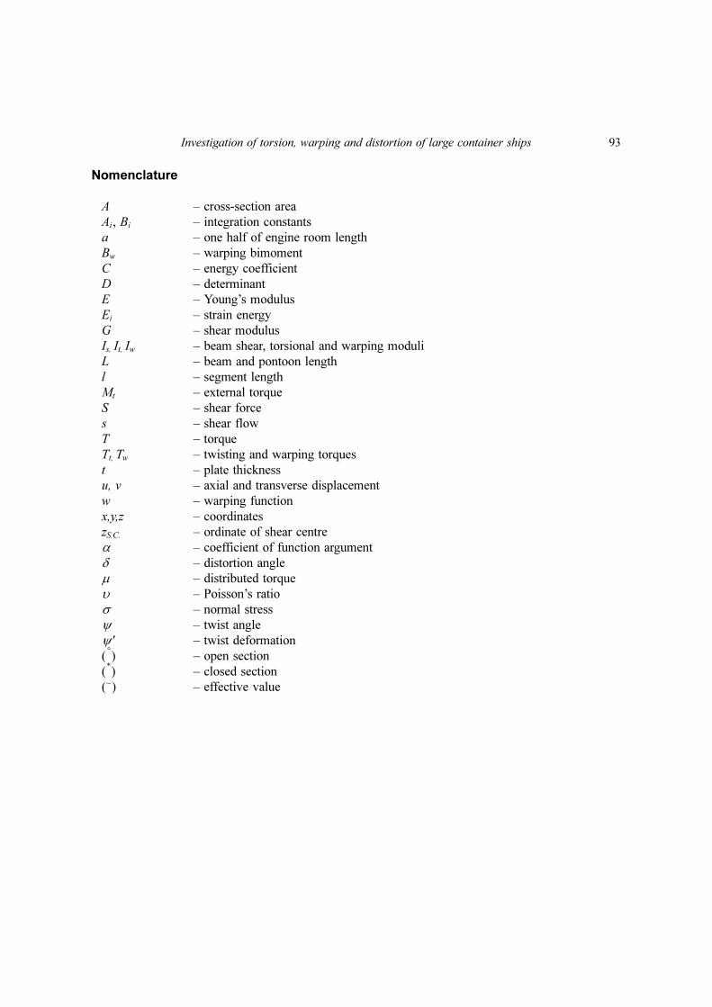
Nomenclature
A – cross-section area
Ai, Bi – integration constants
a – one half of engine room length
Bw – warping bimoment
C – energy coefficient
D – determinant
E – Young’s modulus
Ei – strain energy
G – shear modulus
Is, It, Iw – beam shear, torsional and warping moduli
L – beam and pontoon length
l – segment length
Mt – external torque
S – shear force
s – shear flow
T – torque
Tt, Tw – twisting and warping torques
t – plate thickness
u, v – axial and transverse displacement
w – warping function
x,y,z – coordinates
zS.C. – ordinate of shear centre
α – coefficient of function argument
δ – distortion angle
µ – distributed torque
υ – Poisson’s ratio
σ – normal stress
ψ – twist angle
ψ' – twist deformation
( ) – open section
( ) – closed section
(~) – effective value
°
*