investigation of the mechanism of mg insertion in …lfnazar/publications/chemmater...investigation...
TRANSCRIPT

Investigation of the Mechanism of Mg Insertion in Birnessitein Nonaqueous and Aqueous Rechargeable Mg-Ion BatteriesXiaoqi Sun,† Victor Duffort,† B. Layla Mehdi,‡ Nigel D. Browning,‡ and Linda F. Nazar*,†
†Department of Chemistry, University of Waterloo, Waterloo, ON N2L 3G1, Canada‡Fundamental and Computational Sciences Directorate, Pacific Northwest National Laboratory, Washington 99354, United States
*S Supporting Information
ABSTRACT: Magnesium batteries are an energy storagesystem that potentially offers high energy density, butdevelopment of new high voltage cathode materials andunderstanding of their electrochemical mechanism are criticalto realize its benefits. Herein, we synthesize the layered MnO2polymorph (the birnessite phase) as a nanostructured phasesupported on conductive carbon cloth and compare its electro-chemistry and structural changes when it is cycled as a positiveelectrode material in a Mg-ion battery under nonaqueous oraqueous conditions. X-ray photoelectron spectroscopy andtransmission electron microscopy studies show that a con-version mechanism takes place during cycling in a non-aqueous electrolyte, with the formation of MnOOH, MnO, andMg(OH)2 upon discharge. In aqueous cells, on the other hand, intercalation of Mg2+ ions takes place, accompanied by expulsionof interlayer water and transformation to a spinel-like phase as evidenced by X-ray diffraction. Both systems are structurallyquasireversible. The sharp contrast in behavior in the two electrolytes points to the important role of the desolvation energy ofthe Mg2+ cation in nonaqueous systems.
■ INTRODUCTION
Lithium-ion batteries dominate today’s rechargeable batteriesin both commercial applications and academic research.However, lithium batteries, which employ lithium metal as thenegative electrode, are limited to very special cases such aspolymer electrolytes at present1,2 as the formation of dendritesis very difficult to prevent. To overcome these limitations,current Li-ion technology uses graphite negative electrodes,reducing the theoretical capacity density from 2046 mAh L−1
to ∼850 mAh L−1 and significantly increasing the overallcost. Clearly, utilization of metal negative electrodes (anodes) isa promising way of achieving batteries with higher energydensity and lower cost. Among the various candidates, batteriesthat use Mg metal as the negative electrode are of specialinterest.3 In addition to magnesium’s desirable electro-chemical properties, including a volumetric specific capacity of3833 mAh L−1 and the absence of dendrite growth on depo-sition,4 magnesiummetal is already a material of broad industrialinterest offering good availability and safe handling in ambientatmosphere.The first rechargeable Mg battery prototype was reported
over 15 years ago by Aurbach et al.5 following two majorbreakthroughs: the development of electrolytes based on theassociation of a Grignard species R-Mg-Cl with a strong Lewisacid such as AlCl3
6,7 and the introduction of Chevrel phases,Mo6Ch8 with Ch = S, Se, as positive electrode materialscoupled with a Mg anode.8,9 Despite a low operating voltage of
about 1.1 V versus Mg on discharge, Chevrel electrodes aredifficult to fully recharge at room temperature due to reactivityof the electrolyte at potentials higher than 1.8 V.9−11 Thedevelopment of magnesium batteries has since been hinderedby the difficulty in finding new chorine-free electrolytes able toreversibly strip and cast Mg at low overpotential, which are stableat high potential. Research into new positive electrode (cathode)materials has also proven that the diffusion of Mg2+ ions insolid host structures is more hindered than that of monovalentalkali cations such as Li+ and Na+.12−16 To design new electrodematerials, fundamental studies focusing on the electrochemicalmechanism rather than performance are needed at this point tounderstand the key parameters underpinning the developmentof magnesium-based batteries.Promising candidates for positive electrodes with a higher
voltage than Chevrel phases are manganese oxides, which havebeen extensively investigated in the battery literature owing totheir rich crystal chemistry.17−28 The edge sharing MnO6octahedra can form ribbons of finite width that interconnectto generate tunnel structures such as hollandite (α-MnO2) ortodorokite: these consist of tunnels spanned by (2 × 2) or(3 × 3) octahedra, respectively. Alternatively, bidimensionalstructures consisting of stacked MnO2 planes crystallize either
Received: October 12, 2015Revised: December 15, 2015Published: December 16, 2015
Article
pubs.acs.org/cm
© 2015 American Chemical Society 534 DOI: 10.1021/acs.chemmater.5b03983Chem. Mater. 2016, 28, 534−542

without water in the interlayer space (i.e., O′3-NaMnO2)or insert structural water. The latter are exemplified by theminerals birnessite (Figure 1)29 and buserite, structures thatare characterized by interlayer distances of ∼7 Å and ∼10 Å,respectively.30
Studies of these materials as cathodes for Mg-ion batteries arerather limited. It was recently shown that magnesium cells usingα-MnO2 positive electrodes undergo a conversion mechanism,resulting in poor cyclability.31 Comprehensive analysis by theToyota team demonstrated that the Mg2+ intercalation barrierinto such structures at an early stage is comparable with Li+,but thermodynamics drive the transformation of the highlyunstable product into the rock salt oxide (Mg1-xMnxO) on theouter particle surface.31,32 This conversion mechanism is alsoapplicable to other MnO2 oxides in nonaqueous Mg cellsaccording to experimental studies that show the surface area isthe largest factor influencing their electrochemistry.33 On theother hand, two very recent studies have emphasized thebeneficial role of a high water content in the electrolyte infacilitating Mg2+ intercalation using anhydrous layered MnO2
34
and spinel MgMn2O435 positive electrode materials, which we
became aware of while completing this work. These studiesparallel our interest in exploring the behavior of birnessite in bothaqueous and nonaqueous electrolytes to identify the main factorsthat trigger intercalation or a conversion mechanism.Here, we report a one-step hydrothermal synthesis of nano-
metric platelets of birnessite Mg0.15MnO2·0.9H2O supported oncarbon cloth. The electrochemical performance of this materialwas examined in aqueous media using a 0.5 M Mg(ClO4)2electrolyte and in nonaqueous media using 0.25 M Mg(TFSI)2in diglyme. A detailed analysis of the reaction mechanisms (byX-ray diffraction (XRD), X-ray photoelectron spectroscopy(XPS), Karl Fischer titration, and transmission electronmicroscopy (TEM) studies) reveals a facile intercalation processin aqueous media and a sluggish conversion mechanism innonaqueous cells. On the basis of the contrast of these twosystems, we propose that a principal factor limiting the per-formance of nonaqueous cells is the anion desolvation energy,supporting recent pioneering theoretical studies in bothelectrolyte and cathode development for Mg batteries.36,37
■ EXPERIMENTAL METHODSSynthesis. The birnessite Mg0.15MnO2·0.9H2O/carbon cloth
composite (labeled Mg-bir/CC) was prepared by a hydrothermalmethod. Typically, 150 mg of Mg(MnO4)2·xH2O (Sigma-Aldrich) wasdissolved in 36mL of deionized water and transferred to a Teflon® linedstainless steel autoclave. A square piece of carbon cloth (7 × 7 cm2)(Fuel Cell Earth, 99.5% carbon content) was placed in the autoclaveto serve as the conductive substrate. The mixture was heated at 160 °C
for 2 h. After being cooled to room temperature, the product waswashed with water and dried in air.
Characterization. Powder XRD analyses were performed on aPANalytical Empyrean diffractometer using Cu Kα radiation. Thestructural water content was determined by thermogravimetric analysis(TGA, TA Instruments SDT Q600) using birnessite powder preparedby the same method (but not supported on carbon cloth) with a5 K min−1 heating ramp under N2 flow. Scanning electron microscope(SEM) studies were conducted using a Zeiss Ultra field emission orZeiss Leo 1530 SEM equipped with an energy dispersive X-rayspectroscopy (EDX) detector. TEM images were acquired ona Zeiss Libra 200MC TEM. High-resolution TEM (HRTEM) imagesand electron energy loss spectroscopy (EELS) spectra were obtainedwith FEI TITAN 80−300 eV TEM/STEM operated at 300 kV. Themicroscope was outfitted with a spherical aberration corrector for theprobe-forming lens, enabling sub-Angstrom resolution in the TEMand STEM mode. The electron energy loss spectra were acquired witha monochromated electron gun, providing chemical and electronicstructure analysis with atomic level resolution measurements.
XPS was carried out on a Thermo VG Scientific ESCALab 250instrument. Spectra were processed using Gaussian−Lorentzianfunctions and a Shirley-type background with CasaXPS software andreferenced to adventitious carbon at 285.0 eV.
The water content in the electrolyte was analyzed by Karl Fischertitration (Mettler Toledo Coulometric Karl Fischer Titrator C30).The electrolyte was extracted using dry acetonitrile (Caledon, 99.9%,treated with rigorously dried molecular sieves). Two to three measure-ments were taken for each sample.
Electrochemistry. Mg-bir/CC laminates were punched into disksand directly used as the electrodes after drying at 100 °C under vacuumovernight. The loading of birnessite on the electrode was∼1.5 mg cm−2.In the aqueous system, the material was examined in an electrolytecomposed of 0.5 M Mg(ClO4)2 (Sigma-Aldrich, 99.0%) in deionizedwater using Pt gauze (Sigma-Aldrich, 99.9%) as the counter electrodeand Ag/AgCl (saturated) as the reference electrode in T-shapeSwagelok three-electrode cells. For the nonaqueous system, 0.25 MMg(TFSI)2 in diglyme electrolyte was prepared by dissolving 140 °Cvacuum-dried Mg(TFSI)2 salt (Solvionic, 99.5%) in diglyme (Sigma-Aldrich, 99.5%), which was previously purified by distillation. The watercontent in electrolyte was less than 50 ppm. Carbon counter electrodeswere prepared by casting Black Pearls 2000 (BP2000, Cabot, surfacearea ∼1500 m2 g−1) and poly(vinylidene fluoride) (PVDF, Sigma-Aldrich, average Mw ∼534 000 g mol−1) with a 3:2 weight ratio in1-methyl-2-pyrrolidinone (NMP, Sigma-Aldrich, 99.5%) slurry ontocarbon cloth. The loading of BP2000 was ∼10 mg cm−2. Themagnesium reference electrode was polished with carbide paper(Mastercraft, 180 grit SiC) and cleaned with a Kimwipe inside anAr-filled glovebox before use. The voltage profile for the nonaqueoussystem was studied in three-electrode cells obtained from DPMSolutions Inc.38 The cell has a cylindrical geometry. A Mg ring,sandwiched in-between the positive and negative electrodes, is used asthe reference electrode. Long-term cycling for the nonaqueous systemwas carried out in 2325-type coin cells. Galvanostatic studies wereperformed on a VMP3 cycler (Biologic Instruments, 1C = 250 mA g−1
as calculated from a one electron transfer per formula unit).
■ RESULTS AND DISCUSSION
Materials Characterization. The diffractogram of thepristine sample of Mg0.15MnO2·0.9H2O/carbon cloth composite(labeledMg-bir/CC) (Figure 2a) is composed of the amorphouscarbon cloth scattering and the diffraction peaks of the birnessitephase (ICSD-068917).29 The (001) peak at 12.5° is character-istic of the ∼7 Å spacing of the MnO2 sheets in birnessite dueto its monolayer of structural water (Figure 1). It allows cleardifferentiation from the parent buserite structure that featuresa double layer of structural water and a interplanar distanceof ∼10 Å. The large breadth of the diffraction peaks is in goodagreement with the birnessite nanomorphology observed by
Figure 1. Birnessite crystal structure showing a water monolayerbetween the MnO2 sheets.
Chemistry of Materials Article
DOI: 10.1021/acs.chemmater.5b03983Chem. Mater. 2016, 28, 534−542
535

electron microscopy (Figure 2b). The structural water contentin birnessite was determined to be 0.9 by TGA (Figure S1), inagreement with previously reported values of 0.85.29
The composite morphology consists of a homogeneou ∼1 μmthick coating of birnessite Mg0.15MnO2·0.9H2O wrapped aroundthe ∼7.5 μm diameter fibers of the carbon cloth (Figure 2c). Themineral coating is composed of thin platelets radially arrangedaround the carbon fiber surface, with the platelet plane (of Mg2+
mobility) perpendicular to the fibers (Figure 2d). This assemblyoffers an optimal configuration that can be used directly as apositive electrode material for magnesium cells owing to theunderlying electronically conductive substrate and the nanometricmorphology of the active material that benefits the typically lowmobility of Mg2+ by providing short diffusion pathways.Electrochemistry. Aqueous Cell. The good performance of
birnessite cathodes in Mg aqueous cells or in an organic solventwith a significant amount of water (i.e., 5−20% wt.) has beenpreviously established.34,35 However, in those studies, thebirnessite structure was obtained through the electrochemicalconditioning of a nonhydrated manganese oxide, either MnO2
34
or MgMn2O4.35 Owing to the disordered nature of the birnessite
framework, detailed structural information is not readilyaccessible using XRD. Therefore, substantial differences in thelocal arrangement of the different materials, induced by theconditioning process, could lead to significant differences inthe electrochemical mechanism that are not observable by XRD.
For this reason, we verified the behavior of the Mg-bir/CCcomposite electrodes in aqueous media. Sloping curveswere observed for the discharge and charge voltage profiles(Figure 3a), consistent with previous studies.34,35 As expectedfrom its low surface area, the capacitive response of carbon cloth(∼0.05 mAh g−1 of active material, Figure S2) is negligiblecompared to the initial capacity of 150 mAh/g, i.e., insertion of0.3 Mg2+, as observed here and by others.34,35 The expectedreversible “theoretical” capacity is 0.5 Mg2+ based on a oneelectron transfer (since deep reduction of Mn3+ to Mn2+ istypically not very reversible). However, different from previousreports, capacity fading is observed over the first 20 cycles(Figure 3b). This is due to the enhancement of Mn2+ dissolutiondue to the nanometric size of our active material as well as the lowloading used in this study. Further evidence of this was found bypost-mortem SEM imaging of the dried separator facing theanode, showing the precipitation of large manganese containingparticles (Figure S3).XRD analysis of the composite electrode in the charge
(demagnesiated) and discharge (magnesiated) states (Figure 4a)confirms the magnesium intercalation process in aqueous cells.However, modification of the intercalate concentration changesthe electrostatic interaction responsible for the layered arrange-ment, resulting in a major topotactical transformation of thestructure. Upon discharge, the intercalated Mg2+ allows formore efficient screening of the interslab electrostatic repulsion.
Figure 3. Electrochemistry of Mg-bir/CC in an aqueous electrolyte: (a) voltage profile: (b) capacity and Coulombic efficiency evolution at 2C(a “C” rate being defined with respect to one e− transfer).
Figure 2. (a) XRD comparison of Mg-bir/CC composite (blue; only the index for the peak with highest intensity of the clump is shown for the purposeof clarity) and bare carbon cloth (red); Bragg peak positions for birnessite are noted by the greens tick marks, and reflections from the carbon cloth areindicated by asterisks; (b) TEM image of Mg-bir/CC; (c, d) SEM images of Mg-bir/CC.
Chemistry of Materials Article
DOI: 10.1021/acs.chemmater.5b03983Chem. Mater. 2016, 28, 534−542
536

This triggers a contraction of the interlayer spacing from7 Å to 4.86 Å, as evidenced by the shift of the first diffractionpeak from 12.5° (2θ) to 18.6°. Conversely, the removal ofMg2+ upon charge induces an expansion of the interlayer dis-tance to the 10 Å spacing characteristic of a double layer ofwater between the MnO2 layers in the buserite structure.The (001) and (002) buserite reflections are clearly visibleat 9.2° and 18.4°.The structural evolution in the discharged material implies not
only a contraction of the interlayer spacing, but also a glide of theMnO2 planes. Owing to the poor crystallinity of the phases, fullstructure determination was not possible. Nonetheless, the inter-layer distance of the magnesiated phase (4.86 Å) correspondsexactly to the distance between the octahedral slabs in theMgMn2O4 spinel structure (Figure 4b−d). Comparison of thediffractogramms of the discharged phase and MgMn2O4 clearlyshows the strong relationship between the two structures. Someof the reflections of the spinel structure are extinct in thedischarged phase, the most evident being the (103) reflection at33° (Figure 4d). Thus, we propose that the structure of thedischarged phase is based on the same layer arrangement asthe spinel phase; i.e., Jahn−Teller distorted, partially occupiedtriangular slabs of MnO6 octahedra interconnected by tetra-hedral MgO4 and octahedral MnO6 moieties. The appearanceof a new translational symmetry element, as evidenced by thedisappearance of the (103) spinel reflection, suggests a slightlydifferent stacking scheme that does not exactly reproduce thetridimensional structure of MgMn2O4 (Figure 4c). Attempts tomanually determine the precise stacking sequence using theFAULTS software41 were unsuccessful.The hypothesis of a local structure similar to the spinel phase is
further supported by a previous study that clearly shows theformation of spinel in the discharged state,35 although it was notreported as such. In the latter study, we note that the birnessitephase was obtained through a conditioning of the spinel phasewhere the original kagome layers are probably preserved in thebirnessite phase, thus favoring the reformation of the spinelstructure upon remagnesiation. On the other hand, in the presentstudy, there is no reason to presume a similar arrangement ofmanganese vacancies in the triangular lattice of the pristinebirnessite phase. Therefore, we believe that creation of themanganese vacancies occurs during the contraction of theinterlayer spacing: the stabilization of Mg2+ in the tetrahedralinterlayer site generates a very short (1.84 Å) Mn−Mg distance,
forcing Mn out of the triangular lattice and into the interlayerspace. The arrangement of the created vacancies would induce adifferent stacking scheme than in the spinel structure.The formation of such a small interlayer spacing raises the
question of the fate of the water. There is no available site toaccommodate water in the interlayer space of the dischargedphase. The formation of hydroxl groups, as observed in layeredMnOOH, would imply the reorganization of the entire closepacked oxygen framework and therefore is unlikely. Hence,water is most likely expelled from the structure. We note thatconversion of the layered structure to the spinel is reminscentof the conversion of metastable layered Li0.5MnO2 to themore thermodynamically stable spinel LiMn2O4 on cycling innonaqueous media,42 where similar driving forces are undoubt-edly responsible.
Nonaqueous Cells. Traditional Mg-electrolytes based onGrignard compounds (RMgCl in association with AlCl3) areconsidered highly corrosive to oxide materials, and theirsensitivity to moisture could interfere with the structural watercontained in birnessite. The electrochemical behavior of Mg-bir/CC in nonaqueous solvents was therefore investigated usingthe electrolyte 0.25 M Mg(TFSI)2/diglyme. This electrolyte,reported for the first time by Ha et al.,43 exhibits, in ourexperience, a large overpotential (>2 V) when significant currentflows through a Mg anode. However, magnesium metal can stillbe used as a reference electrode owing to the extremely lowcurrent passed in this case. We first investigated the electro-chemistry in a three-electrode cell,38 with a magnesium referenceelectrode and a capacitive-carbon counter electrode.44 Figure 5,panels a and b show the representative voltage profiles for theeighth cycle at a current density of C/10. The working electrodeexhibits a voltage plateau at ∼1.4 V during discharge and ∼1.7 Vduring charge. Such flat plateaus suggest a two-phase reactionmechanism.45 The almost linear voltage evolution of the carbonelectrode with respect to capacity proves its double layercapacitor behavior,46 validating the use ofMgmetal as a referenceelectrode in this system. However, the three-electrode cellsshowed limited lifetime. Owing to the gradual increase of thewater content in the electrolyte (see later), the surface of thereference electrode is progressively passivated by a film ofmagnesium hydroxide.Thus, typical two-electrode coin cells were used to study
long-term cycling performance and water content evolution(Fig. 5c-e). At both C/5 and C/10 rates, a long conditioning
Figure 4. (a) XRD patterns of cycled birnessite electrodes in the aqueous cell: blue, pristine; green, discharged; red, charged. The tick marks represent theBragg peak position of the birnessite29 (blue) and buserite39 (red) phases, respectively; for the purpose of clarity, only the index for the peak with highestintensity is shown. Arrows indicate the shift of the first reflection corresponding to the “interlayer” distance in the three materials. (b) Representation of thespinel MgMn2O4 showing the stacking of (c) the kagome layers.
40 (d) Comparison of the XRD patterns of dischargedMg-bir/CC and the spinel MgMn2O4.
Chemistry of Materials Article
DOI: 10.1021/acs.chemmater.5b03983Chem. Mater. 2016, 28, 534−542
537
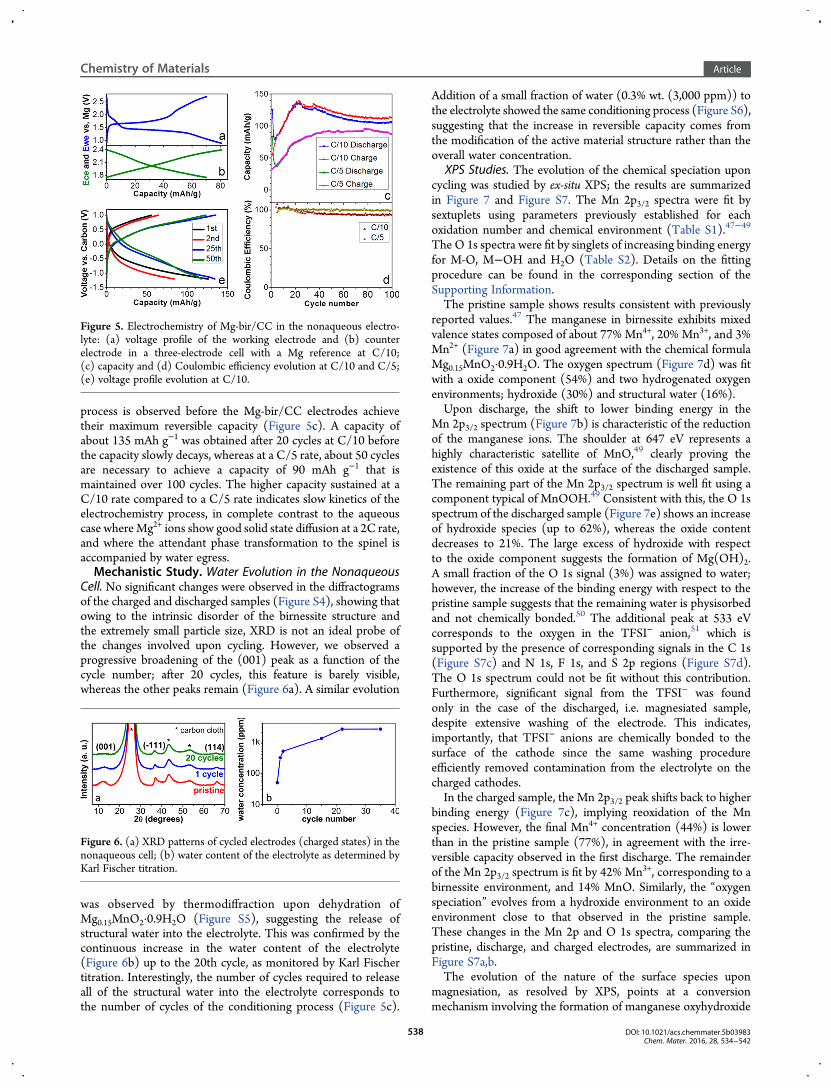
process is observed before the Mg-bir/CC electrodes achievetheir maximum reversible capacity (Figure 5c). A capacity ofabout 135 mAh g−1 was obtained after 20 cycles at C/10 beforethe capacity slowly decays, whereas at a C/5 rate, about 50 cyclesare necessary to achieve a capacity of 90 mAh g−1 that ismaintained over 100 cycles. The higher capacity sustained at aC/10 rate compared to a C/5 rate indicates slow kinetics of theelectrochemistry process, in complete contrast to the aqueouscase whereMg2+ ions show good solid state diffusion at a 2C rate,and where the attendant phase transformation to the spinel isaccompanied by water egress.Mechanistic Study. Water Evolution in the Nonaqueous
Cell. No significant changes were observed in the diffractogramsof the charged and discharged samples (Figure S4), showing thatowing to the intrinsic disorder of the birnessite structure andthe extremely small particle size, XRD is not an ideal probe ofthe changes involved upon cycling. However, we observed aprogressive broadening of the (001) peak as a function of thecycle number; after 20 cycles, this feature is barely visible,whereas the other peaks remain (Figure 6a). A similar evolution
was observed by thermodiffraction upon dehydration ofMg0.15MnO2·0.9H2O (Figure S5), suggesting the release ofstructural water into the electrolyte. This was confirmed by thecontinuous increase in the water content of the electrolyte(Figure 6b) up to the 20th cycle, as monitored by Karl Fischertitration. Interestingly, the number of cycles required to releaseall of the structural water into the electrolyte corresponds tothe number of cycles of the conditioning process (Figure 5c).
Addition of a small fraction of water (0.3% wt. (3,000 ppm)) tothe electrolyte showed the same conditioning process (Figure S6),suggesting that the increase in reversible capacity comes fromthe modification of the active material structure rather than theoverall water concentration.
XPS Studies. The evolution of the chemical speciation uponcycling was studied by ex-situ XPS; the results are summarizedin Figure 7 and Figure S7. The Mn 2p3/2 spectra were fit bysextuplets using parameters previously established for eachoxidation number and chemical environment (Table S1).47−49
The O 1s spectra were fit by singlets of increasing binding energyfor M-O, M−OH and H2O (Table S2). Details on the fittingprocedure can be found in the corresponding section of theSupporting Information.The pristine sample shows results consistent with previously
reported values.47 The manganese in birnessite exhibits mixedvalence states composed of about 77% Mn4+, 20% Mn3+, and 3%Mn2+ (Figure 7a) in good agreement with the chemical formulaMg0.15MnO2·0.9H2O. The oxygen spectrum (Figure 7d) was fitwith a oxide component (54%) and two hydrogenated oxygenenvironments; hydroxide (30%) and structural water (16%).Upon discharge, the shift to lower binding energy in the
Mn 2p3/2 spectrum (Figure 7b) is characteristic of the reductionof the manganese ions. The shoulder at 647 eV represents ahighly characteristic satellite of MnO,49 clearly proving theexistence of this oxide at the surface of the discharged sample.The remaining part of the Mn 2p3/2 spectrum is well fit using acomponent typical of MnOOH.49 Consistent with this, the O 1sspectrum of the discharged sample (Figure 7e) shows an increaseof hydroxide species (up to 62%), whereas the oxide contentdecreases to 21%. The large excess of hydroxide with respectto the oxide component suggests the formation of Mg(OH)2.A small fraction of the O 1s signal (3%) was assigned to water;however, the increase of the binding energy with respect to thepristine sample suggests that the remaining water is physisorbedand not chemically bonded.50 The additional peak at 533 eVcorresponds to the oxygen in the TFSI− anion,51 which issupported by the presence of corresponding signals in the C 1s(Figure S7c) and N 1s, F 1s, and S 2p regions (Figure S7d).The O 1s spectrum could not be fit without this contribution.Furthermore, significant signal from the TFSI− was foundonly in the case of the discharged, i.e. magnesiated sample,despite extensive washing of the electrode. This indicates,importantly, that TFSI− anions are chemically bonded to thesurface of the cathode since the same washing procedureefficiently removed contamination from the electrolyte on thecharged cathodes.In the charged sample, the Mn 2p3/2 peak shifts back to higher
binding energy (Figure 7c), implying reoxidation of the Mnspecies. However, the final Mn4+ concentration (44%) is lowerthan in the pristine sample (77%), in agreement with the irre-versible capacity observed in the first discharge. The remainderof the Mn 2p3/2 spectrum is fit by 42% Mn3+, corresponding to abirnessite environment, and 14% MnO. Similarly, the “oxygenspeciation” evolves from a hydroxide environment to an oxideenvironment close to that observed in the pristine sample.These changes in the Mn 2p and O 1s spectra, comparing thepristine, discharge, and charged electrodes, are summarized inFigure S7a,b.The evolution of the nature of the surface species upon
magnesiation, as resolved by XPS, points at a conversionmechanism involving the formation of manganese oxyhydroxide
Figure 5. Electrochemistry of Mg-bir/CC in the nonaqueous electro-lyte: (a) voltage profile of the working electrode and (b) counterelectrode in a three-electrode cell with a Mg reference at C/10;(c) capacity and (d) Coulombic efficiency evolution at C/10 and C/5;(e) voltage profile evolution at C/10.
Figure 6. (a) XRD patterns of cycled electrodes (charged states) in thenonaqueous cell; (b) water content of the electrolyte as determined byKarl Fischer titration.
Chemistry of Materials Article
DOI: 10.1021/acs.chemmater.5b03983Chem. Mater. 2016, 28, 534−542
538

(MnOOH) and manganese oxide (MnO) as well as magnesiumhydroxide (Mg(OH)2), summarized by the following equation:
+
+ +
⇔ − + −
+ +
+ −x x
x x
x
Mg MnO H O (structural or from electrolyte)
Mg 2 e
(2 0.70)MnO (1.70 2 )MnOOH
( 0.15)Mg(OH)
0.15 2 2
2
2
The voltage plateau observed in the first section of thedischarge in the three electrode cell (Figure 5a) is consistentwith this proposed multiphase process. The reversible capacity(135 mAh g−1) obtained after conditioning of the electrode at aC/10 rate corresponds to about a 0.5 electron transfer perMn atom. However, the change in the mean oxidation state(as measured by XPS) between the discharged and chargedsample, + 2.5 and +3.3, respectively (i.e., a 0.8 e− transfer), islarger than expected showing that the reaction occurspredominantly at the surface of the material. This behavior istypical of conversion reactions, where nucleation and growth ofthe conversion products take place at the interphase betweenelectrode and electrolyte. Propagation of the reaction to the bulkis hindered if the conversion product does not allow for facileMg2+ diffusion. Assuming a simplistic two-phase model, weestimate that about 60% of the active material is involved in theelectrochemical process. We see that despite the nanoscopicmorphology of the active material, the reaction cannot proceed tothe core of the particles: implying the formation of an interphasethat does not conduct Mg2+ ions. The gradual decrease of theionic conductivity of the solid interphase gives rise to the slopingvoltage curve observed in the second part of the discharge.HRTEM and Electron Energy Loss Spectroscopy. HRTEM
analysis was carried out to further characterize the species at thedischarged and charged states. The cathodes used were cycled at90 °C at C/10 with a carbon counter electrode. We employed
a higher temperature here to push the reaction further tocompletion so that the products would be easier to track by TEMwhere only small area could be sampled each time. As shownin Figure S8a, capacities of ∼210 mAh/g are obtained underthese conditions, which approximates to a 0.8 electron transfer.A conditioning process is also required for the cell to achievemaximum capacity (Figure S8b), indicating the same conversionmechanism as observed at room temperature. However, fewercycles are required to reach maximum capacity (i.e., two cycles at90 °C as opposed to 20 cycles at room temperature) because ofthe high temperature, which allows the electrode and electrolyteto reach an equilibrium state more quickly.The EELS spectra shown in Figure 8, panels a and b are
consistent with a conversion reaction. The small changes in theoxygen K-edge indicate that new oxide species are formedon discharge, which agrees with the XPS result where thetransformation from the layered oxide and structural watermatrix to the hydroxide, oxyhydroxide, and oxide mixture isobserved. The reversible change of the Mg K-edge intensity andits energy indicate that Mg-oxide is formed at the cathode duringdischarge and consumed on charge, with the positive charges onMg2+ compensated by the reduction or oxidation of Mn. Thecorresponding change in the Mn valence can be evaluated bythe Mn-L2,3 ratio (Figure 8a). To a first approximation, inthe absence of a detailed calibration curve, we have scaled theobservedMn valence in the pristine birnessite, which is known tobe +3.7 based on chemical analysis. The Mn valence decreasesto +3.2 upon discharge and increases to +3.5 upon charge(Figure 8c). The difference in these values between the Mnvalence calculated from the electrochemical capacities on dis-charge and charge of +2.9 and +3.7, respectively (Figure S8a),indicates an inhomogeneous reaction within the cathode matrix.We were not able to spatially resolve EELS spectra of only thesurface owing to the very highly divided nature of the birnessite.We expect that the core remains as unreacted birnessite, and
Figure 7. (a−c) Mn 2p3/2 and (d−f) O 1s XPS spectra of (a, d) pristine, (b, e) discharged, and (c, f) charged Mg-bir/CC electrodes; fits are shown incolor as labeled.
Chemistry of Materials Article
DOI: 10.1021/acs.chemmater.5b03983Chem. Mater. 2016, 28, 534−542
539
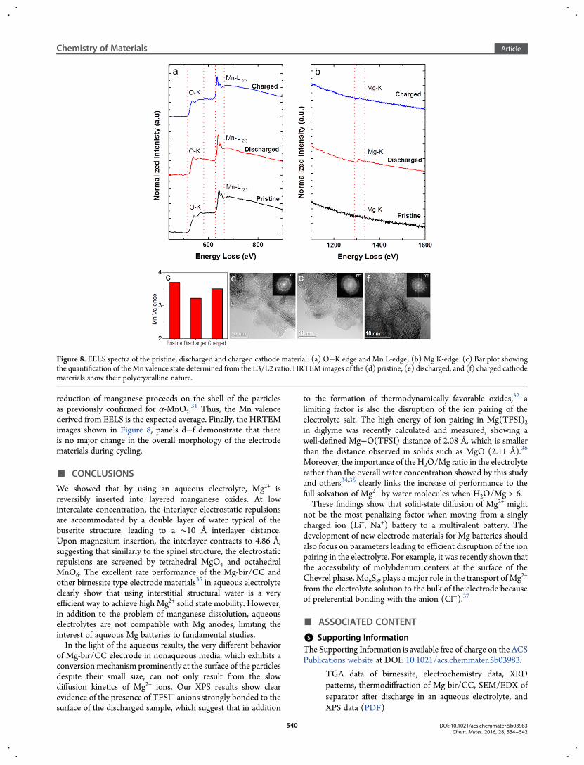
reduction of manganese proceeds on the shell of the particlesas previously confirmed for α-MnO2.
31 Thus, the Mn valencederived from EELS is the expected average. Finally, the HRTEMimages shown in Figure 8, panels d−f demonstrate that thereis no major change in the overall morphology of the electrodematerials during cycling.
■ CONCLUSIONS
We showed that by using an aqueous electrolyte, Mg2+ isreversibly inserted into layered manganese oxides. At lowintercalate concentration, the interlayer electrostatic repulsionsare accommodated by a double layer of water typical of thebuserite structure, leading to a ∼10 Å interlayer distance.Upon magnesium insertion, the interlayer contracts to 4.86 Å,suggesting that similarly to the spinel structure, the electrostaticrepulsions are screened by tetrahedral MgO4 and octahedralMnO6. The excellent rate performance of the Mg-bir/CC andother birnessite type electrode materials35 in aqueous electrolyteclearly show that using interstitial structural water is a veryefficient way to achieve high Mg2+ solid state mobility. However,in addition to the problem of manganese dissolution, aqueouselectrolytes are not compatible with Mg anodes, limiting theinterest of aqueous Mg batteries to fundamental studies.In the light of the aqueous results, the very different behavior
of Mg-bir/CC electrode in nonaqueous media, which exhibits aconversion mechanism prominently at the surface of the particlesdespite their small size, can not only result from the slowdiffusion kinetics of Mg2+ ions. Our XPS results show clearevidence of the presence of TFSI− anions strongly bonded to thesurface of the discharged sample, which suggest that in addition
to the formation of thermodynamically favorable oxides,32 alimiting factor is also the disruption of the ion pairing of theelectrolyte salt. The high energy of ion pairing in Mg(TFSI)2in diglyme was recently calculated and measured, showing awell-defined Mg−O(TFSI) distance of 2.08 Å, which is smallerthan the distance observed in solids such as MgO (2.11 Å).36
Moreover, the importance of theH2O/Mg ratio in the electrolyterather than the overall water concentration showed by this studyand others34,35 clearly links the increase of performance to thefull solvation of Mg2+ by water molecules when H2O/Mg > 6.These findings show that solid-state diffusion of Mg2+ might
not be the most penalizing factor when moving from a singlycharged ion (Li+, Na+) battery to a multivalent battery. Thedevelopment of new electrode materials for Mg batteries shouldalso focus on parameters leading to efficient disruption of the ionpairing in the electrolyte. For example, it was recently shown thatthe accessibility of molybdenum centers at the surface of theChevrel phase, Mo6S8, plays a major role in the transport of Mg2+
from the electrolyte solution to the bulk of the electrode becauseof preferential bonding with the anion (Cl−).37
■ ASSOCIATED CONTENT
*S Supporting InformationThe Supporting Information is available free of charge on the ACSPublications website at DOI: 10.1021/acs.chemmater.5b03983.
TGA data of birnessite, electrochemistry data, XRDpatterns, thermodiffraction of Mg-bir/CC, SEM/EDX ofseparator after discharge in an aqueous electrolyte, andXPS data (PDF)
Figure 8. EELS spectra of the pristine, discharged and charged cathode material: (a) O−K edge and Mn L-edge; (b) Mg K-edge. (c) Bar plot showingthe quantification of theMn valence state determined from the L3/L2 ratio. HRTEM images of the (d) pristine, (e) discharged, and (f) charged cathodematerials show their polycrystalline nature.
Chemistry of Materials Article
DOI: 10.1021/acs.chemmater.5b03983Chem. Mater. 2016, 28, 534−542
540

■ AUTHOR INFORMATIONCorresponding Author*E-mail: [email protected] authors declare no competing financial interest.
■ ACKNOWLEDGMENTSThis work was supported by the Joint Center for Energy StorageResearch (JCESR), an Energy Innovation Hub funded by theU.S. Department of Energy (DOE), Office of Science, BasicEnergy Sciences, and as part of the Chemical Imaging Initiativeconducted under the Laboratory Directed Research andDevelopment Program at Pacific Northwest National Laboratory(PNNL). The HRTEM work was conducted in the William R.Wiley Environmental Molecular Sciences Laboratory (EMSL), anational scientific user facility sponsored by DOE’s Office ofBiological and Environmental Research and located at PNNL.We would like to thank Jeff Aguiar for the help with thequantitative analysis of the energy loss spectra. PNNL, amultiprogram national laboratory, is operated by Battelle forthe Department of Energy under Contract No. DE-AC05-76RLO1830. NSERC is acknowledged by LFN for a CanadaResearch Chair.
■ REFERENCES(1) Armand, M. B.; Chabagno, J.-M.; Duclot, M. J. Poly-esthers as solidelectrolytes. In Fast Ion Transport in Solid Electrodes and Electrolytes;Vashishta, P., Mundy, J.-N., Shenoy, G. K., Eds; North-Holland:Amsterdam, 1979; pp 131−136.(2) Damen, L.; Hassoun, J.; Mastragostino, M.; Scrosati, B. Solid-State,Rechargeable Li/LiFePO4 Polymer Battery for Electric VehicleApplication. J. Power Sources 2010, 195, 6902.(3) Muldoon, J.; Bucur, C. B.; Gregory, T. Quest for NonaqueousMultivalent Secondary Batteries: Magnesium and Beyond. Chem. Rev.2014, 114, 11683−11720.(4) Yoo, H. D.; Shterenberg, I.; Gofer, Y.; Gershinsky, G.; Pour, N.;Aurbach, D.Mg Rechargeable Batteries: anOn-Going Challenge. EnergyEnviron. Sci. 2013, 6, 2265−2279.(5) Aurbach, D.; Lu, Z.; Schechter, A.; Gofer, Y.; Gizbar, H.;Turgeman, R.; Cohen, Y.; Moshkovich, M.; Levi, E. Prototype Systemsfor Rechargeable Magnesium Batteries. Nature 2000, 407, 724−727.(6) Aurbach, D.; Gizbar, H.; Schechter, H.; Chusid, O.; Gottlieb, E. E.;Gofer, Y.; Goldberg, I. Electrolyte Solutions for RechargeableMagnesium Batteries Based on Organomagnesium ChloroaluminateComplexes. J. Electrochem. Soc. 2002, 149, A115−A121.(7) Mizrahi, O.; Amir, N.; Pollak, E.; Chusid, O.; Marks, V.; Gottlieb,H.; Larush, L.; Zinigrad, E.; Aurbach, D. Electrolyte Solutions with aWide Electrochemical Window for Rechargeable Magnesium Batteries.J. Electrochem. Soc. 2008, 155, A103−A109.(8) Lancry, E.; Levi, E.; Gofer, Y.; Levi, M.; Salitra, G.; Aurbach, D.Leaching Chemistry and the Performance of the Mo6S8 Cathodes inRechargeable Mg Batteries. Chem. Mater. 2004, 16, 2832−2838.(9) Levi, E.; Mitelman, A.; Isnard, O.; Brunelli, M.; Aurbach, D. PhaseDiagram ofMg Insertion into Chevrel Phases, MgxMo6T8 (T = S, Se). 3.The Crystal Structure of Triclinic Mg2Mo6Se8. Inorg. Chem. 2008, 47,1975−1983.(10) Yagi, S.; Tanaka, A.; Ichitsubo, T.; Matsubara, E. ElectrochemicalStability of Metal Electrodes for Reversible Magnesium Deposition/Dissolution in Tetrahydrofuran Dissolving Ethylmagnesium Chloride.ECS Electrochem. Lett. 2012, 1, D11−D14.(11) Yagi, S.; Tanaka, A.; Ichikawa, Y.; Ichitsubo, T.; Matsubara, E.Electrochemical Stability of Magnesium Battery Current Collectors in aGrignard Reagent-Based Electrolyte. J. Electrochem. Soc. 2013, 160,C83−C88.(12) Amatucci, G. G.; Badway, F.; Singhal, A.; Beaudoin, B.; Skandan,G.; Bowmer, T.; Plitz, I.; Pereira, N.; Chapman, T.; Jaworski, R.
Investigation of Yttrium and Polyvalent Ion Intercalation intoNanocrystalline Vanadium Oxide. J. Electrochem. Soc. 2001, 148,A940−A950.(13) Levi, E.; Levi, M. D.; Chasid, O.; Aurbach, D. A Review on theProblems of the Solid State Ion Diffusion in Cathodes for RechargeableMg Batteries. J. Electroceram. 2009, 22, 13−19.(14) Liu, M.; Rong, Z.; Malik, R.; Canepa, P.; Jain, A.; Ceder, G.;Persson, K. A. Spinel Compounds as Multivalent Battery Cathodes: aSystematic Evaluation Based on Ab Initio Calculations. Energy Environ.Sci. 2015, 8, 964−974.(15) Gautam, G. S.; Canepa, P.; Malik, R.; Liu, M.; Persson, K. A.;Ceder, G. First-Principles Evaluation of Multi-Valent Cation Insertioninto Orthorhombic V2O5. Chem. Commun. 2015, 51, 13619−13622.(16) Bo, S.-H.; Grey, C. P.; Khalifah, P. G. Defect-Tolerant DiffusionChannels for Mg2+ Ions in Ribbon-Type Borates: Structural Insightsinto Potential Battery Cathodes MgVBO4 and MgxFe2‑xB2O5. Chem.Mater. 2015, 27, 4630−4639.(17) Thackeray, M. M.; Johnson, P. J.; de Picciotto, L. A.; Bruce, P. G.;Goodenough, J. B. Electrochemical Extraction of Lithium fromLiMn2O4. Mater. Res. Bull. 1984, 19, 179−187.(18) Bach, S.; Pereira-Ramos, J. P.; Baffier, N.; Messina, R. BirnessiteManganese Dioxide Synthesized via a Sol-Gel Process: a NewRechargeable Cathodic Material for Lithium Batteries. Electrochim.Acta 1991, 36, 1595−1603.(19) Bach, S.; Pereira-Ramos, J. P.; Baffier, N. A New MnO2 TunnelRelated Phase as Host Lattice for Li Intercalation. Solid State Ionics 1995,80, 151−158.(20) Feng, Q.; Kanoh, H.;Miyai, Y.; Ooi, K. Hydrothermal Synthesis ofLithium and Sodium Manganese Oxides and Their Metal IonExtraction/Insertion Reactions. Chem. Mater. 1995, 7, 1226−1232.(21) Duncan, M. J.; Leroux, F.; Corbett, J. M.; Nazar, L. F. Todorokiteas a Li Insertion Cathode. J. Electrochem. Soc. 1998, 145, 3746−3757.(22) Luo, J.-Y.; Zhang, J.-J.; Xia, Y.-Y. Highly Electrochemical Reactionof Lithium in the OrderedMesoporous β-MnO2.Chem.Mater. 2006, 18,5618−5623.(23) Caballero, A.; Hernan, L.; Morales, J.; Sanchez, L.; Santos Pena, J.;Aranda, M. A. G. Synthesis and Characterization of High-TemperatureHexagonal P2-Na0.6MnO2 and Its Electrochemical Behaviour as aCathode in Sodium Cells. J. Mater. Chem. 2002, 12, 1142−1147.(24) Nam, K. W.; Kim, S.; Yang, E.; Jung, Y.; Levi, E.; Aurbach, D.;Choi, J. W. Critical Role of Crystal Water for a Layered CathodeMaterial in Sodium Ion Batteries. Chem. Mater. 2015, 27, 3721−3725.(25) Rasul, S.; Suzuki, S.; Yamaguchi, S.; Miyayama, M. High CapacityPositive Electrodes for Secondary Mg-Ion Batteries. Electrochim. Acta2012, 82, 243−249.(26) Zhang, R.; Yu, X.; Nam, K.-W.; Ling, C.; Arthur, T. S.; Song, W.;Knapp, A.; Ehrlich, S. N.; Yang, X.-Q.; Matsui, M. α-MnO2 as a CathodeMaterial for Rechargeable Mg Batteries. Electrochem. Commun. 2012, 23,110−113.(27) Ling, C.; Mizuno, F. Phase Stability of Post-spinel CompoundAMn2O4 (A = Li, Na, or Mg) and Its Application as a RechargeableBattery Cathode. Chem. Mater. 2013, 25, 3062−3071.(28) Huie, M. M.; Bock, D. C.; Takeuchi, E. S.; Marschilok, A. C.;Takeuchi, K. J. Cathode Materials for Magnesium and Magnesium-IonBased Batteries. Coord. Chem. Rev. 2015, 287, 15−27.(29) Post, J. E.; Veblen, D. R. Crystal Structure Determinations ofSynthetic Sodium, Magnesium and Potassium Birnessite Using TEMand the Rietveld Method. Am. Mineral. 1990, 75, 477−489.(30) Golden, D. C.; Chen, C. C.; Dixon, J. B. Transformation ofBirnessite to Buserite, Todorokite, and Manganite under MildHydrothermal Treatment. Clays Clay Miner. 1987, 35, 271−280.(31) Arthur, T. S.; Zhang, R.; Ling, C.; Glans, P.-A.; Fan, X.; Guo, J.;Mizuno, F. Understanding the Electrochemical Mechanism of K-αMnO2 for Magnesium Battery Cathodes. ACS Appl. Mater. Interfaces2014, 6, 7004−7008.(32) Ling, C.; Zhang, R.; Arthur, T. S.; Mizuno, F. How General is theConversion Reaction in Mg Battery Cathode: A Case Study of theMagnesiation of α-MnO2. Chem. Mater. 2015, 27, 5799−5807.
Chemistry of Materials Article
DOI: 10.1021/acs.chemmater.5b03983Chem. Mater. 2016, 28, 534−542
541

(33) Zhang, R.; Arthur, T. S.; Ling, C.; Mizuno, F. Manganese Dioxidesas Rechargeable Magnesium Battery Cathode; Synthetic Approach toUnderstandMagnesiation Process. J. Power Sources 2015, 282, 630−638.(34) Song, J.; Noked, M.; Gillette, E.; Duay, J.; Rubloff, G.; Lee, S. B.Activation of aMnO2Cathode byWater-StimulatedMg2+ Insertion for aMagensium Ion Battery. Phys. Chem. Chem. Phys. 2015, 17, 5256−5264.(35) Nam, K. W.; Kim, S.; Lee, S.; Salama, M.; Shterenberg, I.; Gofer,Y.; Kim, J.-S.; Yang, E.; Park, C. S.; Kim, J.-S.; Lee, S.-S.; Chang, W.-S.;Doo, S.-G.; Jo, Y. N.; Jung, Y.; Aurbach, D.; Choi, J. W. The HighPerformance of Crystal Water Containing Manganese BirnessiteCathodes for Magnesium Batteries. Nano Lett. 2015, 15, 4071−4079.(36) Lapidus, S. H.; Rajput, N. N.; Qu, X.; Chapman, K. W.; Persson,K. A.; Chupas, P. J. Solvation Structure and Energetics of Electrolytes forMultivalent Energy Storage. Phys. Chem. Chem. Phys. 2014, 16, 21941−21945.(37) Wan, L. F.; Perdue, B. R.; Apblett, C. A.; Prendergast, D. MgDesolvation and Intercalation Mechanism at the Mo6S8 Chevrel PhaseSurface. Chem. Mater. 2015, 27, 5932−5940.(38) Periyapperuma, K.; Tran, T. T.; Trussler, S.; Ioboni, D.; Obrovac,M. N. Conflat Two and Three Electrode Electrochemical Cells. J.Electrochem. Soc. 2014, 161, A2182−A2187.(39) Kuma, K.; Usui, A.; Paplawsky, W.; Gedulin, B.; Arrhenius, G.Crystal Structures of Synthetic 7 Å and 10 ÅManganates Substituted byMono- and Divalent Cations. Mineral. Mag. 1994, 58, 425−447.(40) Irani, K. S.; Sinha, A. P. B.; Biswas, A. B. Effect of Temperature onthe Structure of Manganites. J. Phys. Chem. Solids 1962, 23, 711−727.(41) Casas-Cabanas, M.; Rodríguez-Carvajal, J.; Palacín, M. R. Faults, aNew Program for Refinement of Powder Diffraction Patterns fromLayered Structures. Z. Kristallogr. Suppl. 2006, 2006, 243−248.(42) Armstrong, A. R.; Paterson, A. J.; Dupre, N.; Grey, C. P.; Bruce, P.G. Structural Evolution of Layered LixMnyO2: Combined Neutron,NMR, and Electrochemical Study. Chem. Mater. 2007, 19, 1016−1023.(43) Ha, S.-Y.; Lee, Y.-W.; Woo, S. W.; Koo, B.; Kim, J.-S.; Cho, J.; Lee,K. T.; Choi, N.-S. Magnesium (II) Bis(trifluoromethane sulfonyl)Imide-Based Electrolytes with Wide Electrochemical Windows forRechargeable Magnesium Batteries. ACS Appl. Mater. Interfaces 2014, 6,4063−4073.(44) Yoo, H. D.; Shterenberg, I.; Gofer, Y.; Doe, R. E.; Fischer, C. C.;Ceder, G.; Aurbach, D. A Magnesium-Activated Carbon HybridCapacitor. J. Electrochem. Soc. 2014, 161, A410−A415.(45) Van der Ven, A.; Bhattacharya, J.; Belak, A. A. Understanding LiDiffusion in Li-Intercalation Compounds. Acc. Chem. Res. 2013, 46,1216−1225.(46) Frackowiak, E.; Beguin, F. Carbon Materials for the Electro-chemical Storage of Energy in Capacitors. Carbon 2001, 39, 937−950.(47) Gupta, R. P.; Sen, S. K. Calculation of Multiplet Structure of Corep-Vacancy Levels. Phys. Rev. B 1974, 10, 71−77.(48) Nesbitt, H. W.; Banerjee, D. Interpretation of XPS Mn(2p)Spectra of Mn Oxyhydroxides and Constraints on the Mechanism ofMnO2 Precipitation. Am. Mineral. 1998, 83, 305−315.(49) Biesinger, M. C.; Payne, B. P.; Grosvenor, A. P.; Lau, L. W. M.;Gerson, A. R.; Smart, R., St. C. Resolving Surface Chemical States inXPS Analysis of First Row Transition Metals, Oxides and Hydroxides:Cr, Mn, Fe, Co and Ni. Appl. Surf. Sci. 2011, 257, 2717−2730.(50) Knipe, S. W.; Mycroft, J. R.; Pratt, A. R.; Nesbitt, H. W.; Bancroff,G. M. X-Ray Photoelectron Spectroscopic Study of Water Adsorptionon Iron Sulphide Minerals. Geochim. Cosmochim. Acta 1995, 59, 1079−1090.(51) Dedryvere, R.; Leroy, S.; Martinez, H.; Blanchard, F.; Lemordant,D.; Gonbeau, D. XPS Valence Characterization of Lithium Salts as aTool to Study Electrode/Electrolyte Interfaces of Li-Ion Batteries. J.Phys. Chem. B 2006, 110, 12986−12992.
Chemistry of Materials Article
DOI: 10.1021/acs.chemmater.5b03983Chem. Mater. 2016, 28, 534−542
542