investigation of the february 1, 2014 collapse of a ... of the february 1, ... this report was...
TRANSCRIPT
Investigation of the February 1, 2014 Collapse of a Telecommunication Tower at the Summit Park Community in Clarksburg, WV U.S. Department of Labor Occupational Safety and Health Administration Directorate of Construction
July 2014

Investigation of the February 1, 2014 Collapse of a Telecommunication Tower at the Summit Park Community in Clarksburg, WV
_____________________________________________________________________________________________
2
TABLE OF CONTENTS PAGE NO.
Introduction………………………………………………………….......3
The Project……………………………………………………………….3
The Incident……………………………………………………………...5
Observation of the Collapsed Tower….………………………………...7
Analysis…………………………………………………………………..11
Discussion………………………………………………………………...15
Conclusions……………………………………………………………….17
Attachment A – Selected Pages of the Related Industry Standards.
Attachment B – Evaluation of the Capacity of the Horizontal Braces as the Anchorage for the Personal Fall Arrest System.
This report was prepared by Mohammad Ayub, P.E., S.E. Scott Jin, Ph.D., P.E. Office of Engineering Services Directorate of Construction

Investigation of the February 1, 2014 Collapse of a Telecommunication Tower at the Summit Park Community in Clarksburg, WV
_____________________________________________________________________________________________
3
Introduction
On February 1, 2014, at approximately 11:37 a.m., a 340'-high guyed telecommunication tower (cell tower), suddenly collapsed during upgrading/construction activities. Four employees were working on the tower removing its diagonals. In the process, no temporary supports were installed. As a result of the tower’s collapse, two employees were killed and two others were badly injured. The cell tower fell onto the guy wires of an adjacent smaller cell tower and caused it to collapse, killing a firefighter while he was rescuing the injured employees on the ground. The collapse of the smaller tower is not covered in this investigation.
The Occupational Safety and Health Administration’s (OSHA) Regional Administrator, Region III, asked the Directorate of Construction (DOC) in OSHA’s National Office in Washington, DC, to provide technical assistance in a causal determination and to provide engineering assistance to the OSHA Charleston Area Office in its investigation. A civil engineer from the DOC visited the incident site from February 5–7 to inspect the collapsed tower, examine the failed pieces, and discuss the sequence of events with representatives of the tower’s owner.
DOC reviewed the following documents:
• Photographs of the incident taken by the OSHA Charleston Area Office. • Notes and records (27 pages) from the West Virginia State Police (WVSP). • Taped records of four witness interviews conducted by WVSP. • Photographs of the incident taken by WVSP. • Inspection report on Despard Tower 1, prepared by FDH Engineering, Inc., April 2013. • Original design of Despard Tower 1, certified by Thomas W. Schepke, PE, UNR-ROHN,
October 1990. • Modification Drawings of Despard Tower 1, prepared by FDH Engineering, Inc., August
2013. • ANSI/TIA-222-G-2005 Structural Standard for Antenna Supporting Structures and Antennas,
Telecommunication Industry Association, August 2005 (Reaffirmed: December 20, 2012). • ANSI/TIA-1019-A Standard for Installation, Alteration and Maintenance of Antenna
Supporting Structures and Antennas, Telecommunication Industry Association, September 2012.
The Project
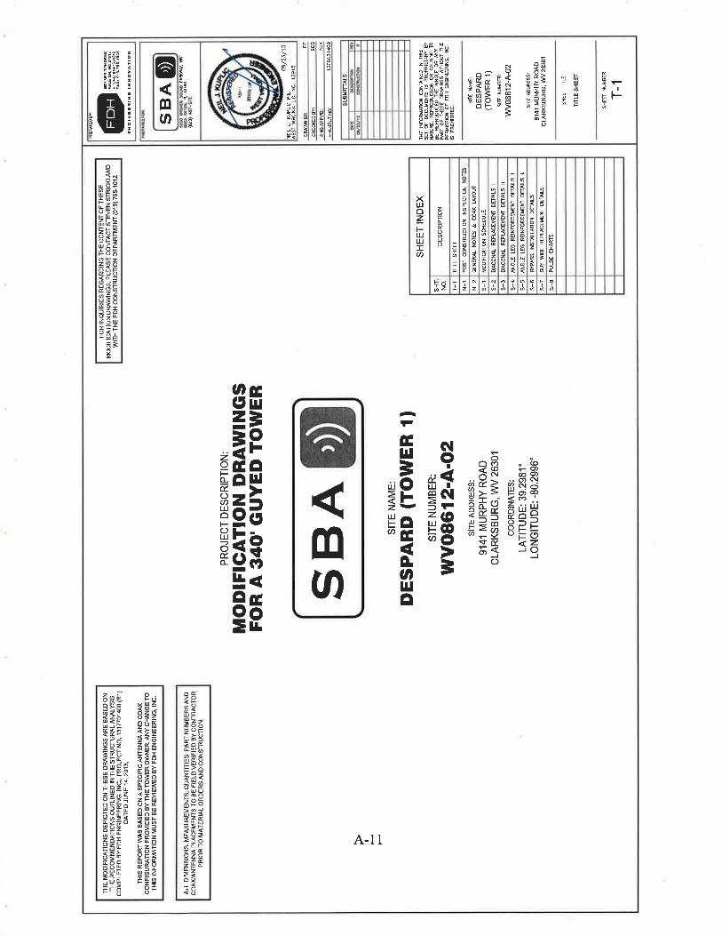
The project was to upgrade and modify an existing 340' guyed cell tower by replacing diagonals, adding angle leg reinforcements, and replacing guy wires (See Figure 1). The tower was located at the Summit Park Community, Harrison County, West Virginia. The site name was Despard (Tower 1). The site number was WV08612-A-02. The site address was 9141 Murphy’s Run Road, Clarksburg, West Virginia.
Investigation of the February 1, 2014 Collapse of a Telecommunication Tower at the Summit Park Community in Clarksburg, WV
_____________________________________________________________________________________________
4
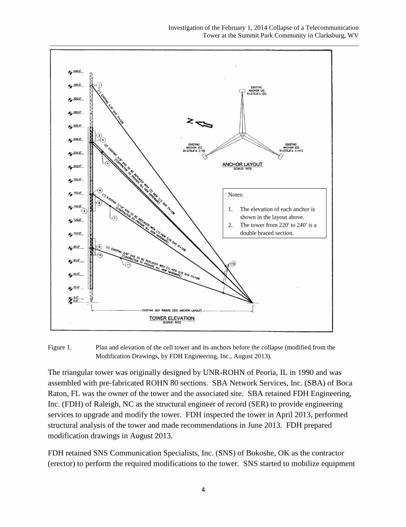
Figure 1. Plan and elevation of the cell tower and its anchors before the collapse (modified from the Modification Drawings, by FDH Engineering, Inc., August 2013).
The triangular tower was originally designed by UNR-ROHN of Peoria, IL in 1990 and was assembled with pre-fabricated ROHN 80 sections. SBA Network Services, Inc. (SBA) of Boca Raton, FL was the owner of the tower and the associated site. SBA retained FDH Engineering, Inc. (FDH) of Raleigh, NC as the structural engineer of record (SER) to provide engineering services to upgrade and modify the tower. FDH inspected the tower in April 2013, performed structural analysis of the tower and made recommendations in June 2013. FDH prepared modification drawings in August 2013.
FDH retained SNS Communication Specialists, Inc. (SNS) of Bokoshe, OK as the contractor (erector) to perform the required modifications to the tower. SNS started to mobilize equipment
Notes:
1. The elevation of each anchor is shown in the layout above.
2. The tower from 220' to 240' is a double braced section.

Investigation of the February 1, 2014 Collapse of a Telecommunication Tower at the Summit Park Community in Clarksburg, WV
_____________________________________________________________________________________________
5
and materials at the site on January 27, 2014. SNS started the construction work by placing new guy wires on the ground and prepared to replace diagonals on the tower as identified by FDH.
The Incident
February 1, 2014, the day of the incident, was the first day SNS began construction activities on the tower. SNS had a foreman and five employees at the site. Three employees, one on each face of the tower, started to remove the existing diagonals from the tower legs at approximately 70' from the ground and progressed upward. The fourth employee was bringing the removed diagonals from the tower down to the ground and to the welder (the fifth employee) at the workstation approximately 50' away from the tower base. Based on the actual hole distance of the removed diagonals, the welder would cut new steel angle pieces, drill holes at its ends, paint and take pictures before sending them up as replacements.
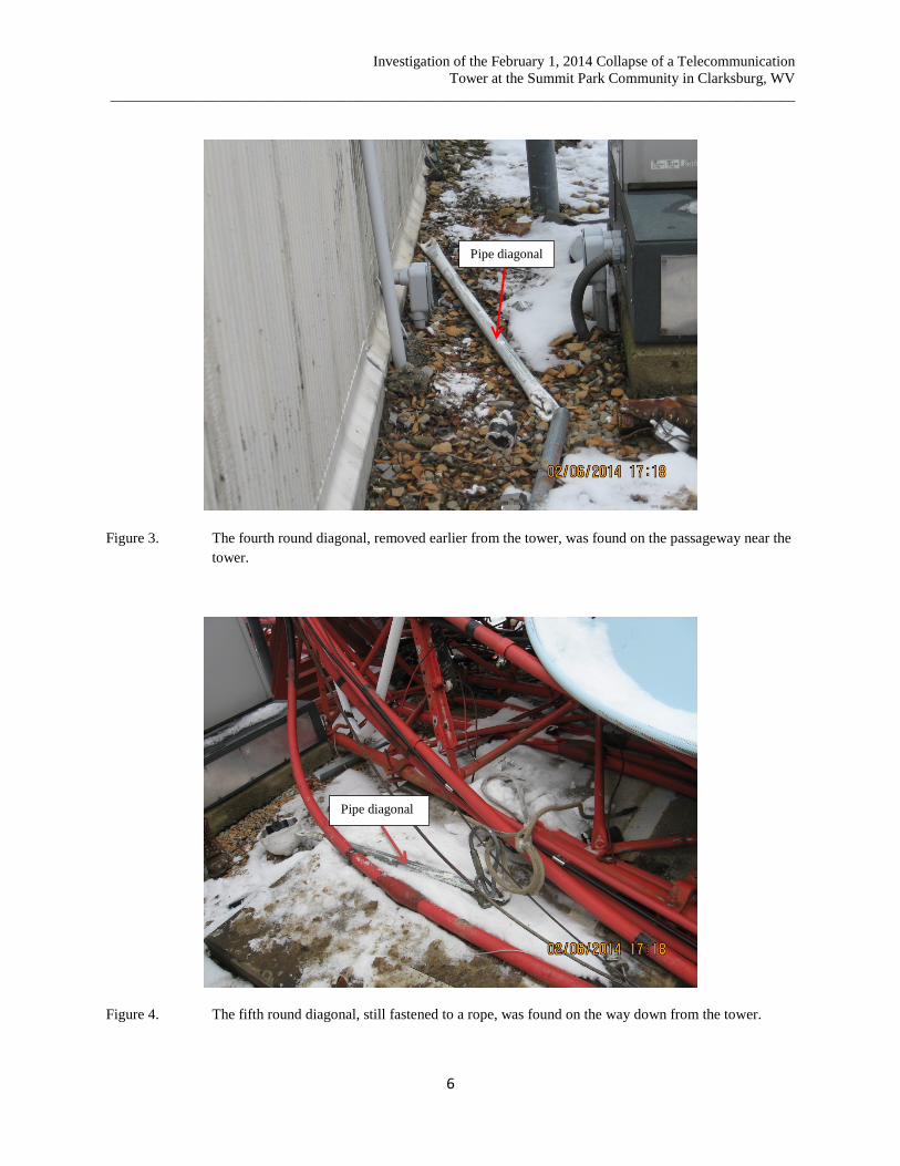
The old diagonals were removed without installing any temporary supports to offset the loss of strength of the tower. The tower suddenly collapsed at approximately 11:37 a.m. At the time of the collapse, two old pipe diagonals and one old steel angle diagonal were identified at the workstation (Figure 2). One old pipe diagonal was located on the passageway near the tower (Figure 3). Another old diagonal that was wrapped with a rope remained in place on the way down from the tower (Figure 4). Thus, a total of five old diagonals were recovered at the site away from the tower. In addition, SBA safety personnel also recovered eight used (old) connecting bolts from the work bags of the injured employees. It is believed that these bolts were used to connect the diagonals at the lugs of the tower legs.
Figure 2. Two old pipe diagonals and one old steel angle diagonal were found at the workstation.
Pipe diagonals
Steel angle diagonal
Investigation of the February 1, 2014 Collapse of a Telecommunication Tower at the Summit Park Community in Clarksburg, WV
_____________________________________________________________________________________________
6
Figure 3. The fourth round diagonal, removed earlier from the tower, was found on the passageway near the
tower.
Figure 4. The fifth round diagonal, still fastened to a rope, was found on the way down from the tower.
Pipe diagonal
Pipe diagonal
Investigation of the February 1, 2014 Collapse of a Telecommunication Tower at the Summit Park Community in Clarksburg, WV
_____________________________________________________________________________________________
7
Observations of the Collapsed Tower
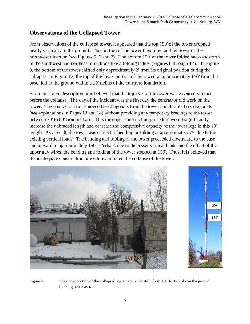
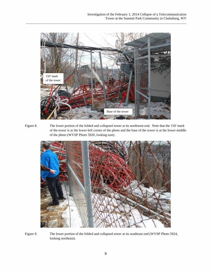
From observations of the collapsed tower, it appeared that the top 190' of the tower dropped nearly vertically to the ground. This portion of the tower then tilted and fell towards the northwest direction (see Figures 5, 6 and 7). The bottom 150' of the tower folded back-and-forth in the southwest and northeast directions like a folding ladder (Figures 8 through 12). In Figure 8, the bottom of the tower shifted only approximately 2' from its original position during the collapse. In Figure 12, the top of the lower portion of the tower, at approximately 150' from the base, fell to the ground within a 10' radius of the concrete foundation.
From the above description, it is believed that the top 190' of the tower was essentially intact before the collapse. The day of the incident was the first day the contractor did work on the tower. The contractor had removed five diagonals from the tower and disabled six diagonals (see explanations in Pages 13 and 14) without providing any temporary bracings to the tower between 70' to 80' from its base. This improper construction procedure would significantly increase the unbraced length and decrease the compressive capacity of the tower legs in this 10' length. As a result, the tower was subject to bending or folding at approximately 75' due to the existing vertical loads. The bending and folding of the tower proceeded downward to the base and upward to approximately 150'. Perhaps due to the lesser vertical loads and the effect of the upper guy wires, the bending and folding of the tower stopped at 150'. Thus, it is believed that the inadequate construction procedures initiated the collapse of the tower.
Figure 5. The upper portion of the collapsed tower, approximately from 150' to 190' above the ground (looking northeast).
-150'
-190'

Investigation of the February 1, 2014 Collapse of a Telecommunication Tower at the Summit Park Community in Clarksburg, WV
_____________________________________________________________________________________________
8
Figure 6. The upper portion of the collapsed tower, approximately from 175' to 240' above the ground (looking northeast).
Figure 7. The upper portion of the collapsed tower, approximately from 220' to the top of the tower at 340'
above the ground (looking northeast).
-175'
-240'
-220'
-340'
Investigation of the February 1, 2014 Collapse of a Telecommunication Tower at the Summit Park Community in Clarksburg, WV
_____________________________________________________________________________________________
9
Figure 8. The lower portion of the folded and collapsed tower at its northwest end. Note that the 150' mark of the tower is at the lower-left corner of the photo and the base of the tower is at the lower-middle of the photo (WVSP Photo 5920, looking east).
Figure 9. The lower portion of the folded and collapsed tower at its southeast end (WVSP Photo 5924, looking northeast).
Base of the tower
150' mark of the tower
Investigation of the February 1, 2014 Collapse of a Telecommunication Tower at the Summit Park Community in Clarksburg, WV
_____________________________________________________________________________________________
10
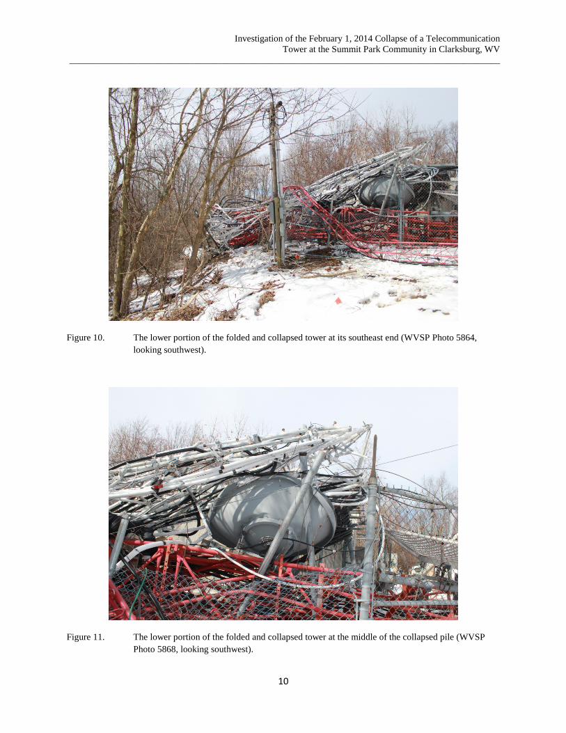
Figure 10. The lower portion of the folded and collapsed tower at its southeast end (WVSP Photo 5864, looking southwest).
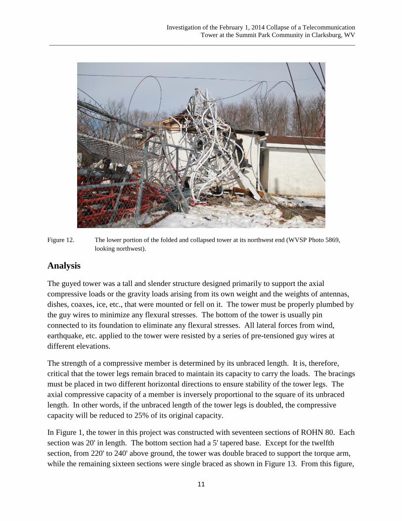
Figure 11. The lower portion of the folded and collapsed tower at the middle of the collapsed pile (WVSP Photo 5868, looking southwest).
Investigation of the February 1, 2014 Collapse of a Telecommunication Tower at the Summit Park Community in Clarksburg, WV
_____________________________________________________________________________________________
11
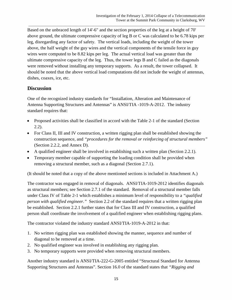
Figure 12. The lower portion of the folded and collapsed tower at its northwest end (WVSP Photo 5869, looking northwest).
Analysis
The guyed tower was a tall and slender structure designed primarily to support the axial compressive loads or the gravity loads arising from its own weight and the weights of antennas, dishes, coaxes, ice, etc., that were mounted or fell on it. The tower must be properly plumbed by the guy wires to minimize any flexural stresses. The bottom of the tower is usually pin connected to its foundation to eliminate any flexural stresses. All lateral forces from wind, earthquake, etc. applied to the tower were resisted by a series of pre-tensioned guy wires at different elevations.
The strength of a compressive member is determined by its unbraced length. It is, therefore, critical that the tower legs remain braced to maintain its capacity to carry the loads. The bracings must be placed in two different horizontal directions to ensure stability of the tower legs. The axial compressive capacity of a member is inversely proportional to the square of its unbraced length. In other words, if the unbraced length of the tower legs is doubled, the compressive capacity will be reduced to 25% of its original capacity.
In Figure 1, the tower in this project was constructed with seventeen sections of ROHN 80. Each section was 20' in length. The bottom section had a 5' tapered base. Except for the twelfth section, from 220' to 240' above ground, the tower was double braced to support the torque arm, while the remaining sixteen sections were single braced as shown in Figure 13. From this figure,

Investigation of the February 1, 2014 Collapse of a Telecommunication Tower at the Summit Park Community in Clarksburg, WV
_____________________________________________________________________________________________
12
the tower was triangular in shape. Each tower leg consisted of 2" diameter steel pipes. They were 41" apart. The unbraced length of the tower leg was approximately 4'-10" for the single-braced section and 2'-5" for the double-braced section.
Figure 13. ROHN Standard 80 Series guyed tower section (modified from ROHN Products LLC, Product Catalog No. 3, Page 155, 2013).
4ʹ-1
0"
2ʹ-5
"

Investigation of the February 1, 2014 Collapse of a Telecommunication Tower at the Summit Park Community in Clarksburg, WV
_____________________________________________________________________________________________
13
In Figure 14, at each welded lug of the tower leg, there was one bolt connecting two diagonals. One diagonal had two holes for connection, one at each end. Thus, removing one bolt would disable two diagonals, although they would still be connected to the tower at the other ends. Figure 15 shows a disabled diagonal still attached to the collapsed tower.
Figure 14. Welded lug of the tower leg; one bolt connects two diagonals.
Figure 15. A diagonal disabled by being unbolted from the lug. It is still attached to the tower.
Welded lug of the tower leg
Disabled diagonal

Investigation of the February 1, 2014 Collapse of a Telecommunication Tower at the Summit Park Community in Clarksburg, WV
_____________________________________________________________________________________________
14
Removing bolts at each end of one diagonal would separate the diagonal completely from the tower but this would also disable two adjacent diagonals. For simplicity, three faces of the triangular tower are laid out in one plane as shown in the upper portion of Figure 16. In this figure, when eight bolts were removed, it produced six disabled diagonals (in dash lines) and five separated diagonals (in red lines). It should be noted that the numbers of removed bolts, disabled diagonals, and separated diagonals were consistent with the collections from the incident site.
Figure 16. Determination of the Unbraced Length of the Tower Legs.
Principles of structural mechanics require that a column be laterally braced in two principal directions. When the unbraced lengths in the two directions are not equal, the longer unbraced length governs, if the sectional properties of the column are same in these two directions. Thus, from the configurations and explanations in Figure 16, the unbraced length of each tower leg was estimated to be 9'-8" for leg A, and 14'-6" for legs B and C.
Notes:
1. Dash line is the disabled diagonal.
2. Red line is the removed (separated) diagonal.
3. X is the location of the removed connection bolt.
For Leg A, the unbraced length in face AB is 9'-8" and in face AC is 9'-8". Thus, the unbraced length of 9'-8" is used for Leg A.
For Leg B, the unbraced length in face BA is 14'-6" and in face BC is 9'-8". Thus, the unbraced length of 14'-6" is used for Leg B.
For Leg C, the unbraced length in face CB is 14'-6" and in face CA is 9'-8". Thus, the unbraced length of 14'-6" is used for Leg C.
Investigation of the February 1, 2014 Collapse of a Telecommunication Tower at the Summit Park Community in Clarksburg, WV
_____________________________________________________________________________________________
15
Based on the unbraced length of 14'-6" and the section properties of the leg at a height of 70' above ground, the ultimate compressive capacity of leg B or C was calculated to be 6.78 kips per leg, disregarding any factor of safety. The vertical loads, including the weight of the tower above, the half weight of the guy wires and the vertical components of the tensile force in guy wires were computed to be 8.82 kips per leg. The actual vertical load was greater than the ultimate compressive capacity of the leg. Thus, the tower legs B and C failed as the diagonals were removed without installing any temporary supports. As a result, the tower collapsed. It should be noted that the above vertical load computations did not include the weight of antennas, dishes, coaxes, ice, etc.
Discussion
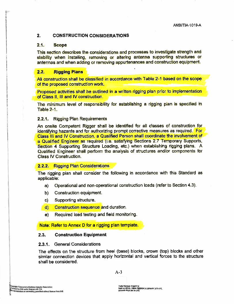
One of the recognized industry standards for “Installation, Alteration and Maintenance of Antenna Supporting Structures and Antennas” is ANSI/TIA -1019-A-2012. The industry standard requires that:
• Proposed activities shall be classified in accord with the Table 2-1 of the standard (Section 2.2).
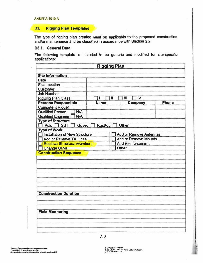
• For Class II, III and IV construction, a written rigging plan shall be established showing the construction sequence, and “procedures for the removal or reinforcing of structural members” (Section 2.2.2, and Annex D).
• A qualified engineer shall be involved in establishing such a written plan (Section 2.2.1). • Temporary member capable of supporting the loading condition shall be provided when
removing a structural member, such as a diagonal (Section 2.7.1).
(It should be noted that a copy of the above mentioned sections is included in Attachment A.)
The contractor was engaged in removal of diagonals. ANSI/TIA-1019-2012 identifies diagonals as structural members; see Section 2.7.1 of the standard. Removal of a structural member falls under Class IV of Table 2-1 which establishes a minimum level of responsibility to a “qualified person with qualified engineer.” Section 2.2 of the standard requires that a written rigging plan be established. Section 2.2.1 further states that for Class III and IV construction, a qualified person shall coordinate the involvement of a qualified engineer when establishing rigging plans.
The contractor violated the industry standard ANSI/TIA-1019-A-2012 in that:
1. No written rigging plan was established showing the manner, sequence and number of diagonal to be removed at a time.
2. No qualified engineer was involved in establishing any rigging plan. 3. No temporary supports were provided when removing structural members.
Another industry standard is ANSI/TIA-222-G-2005 entitled “Structural Standard for Antenna Supporting Structures and Antennas”. Section 16.0 of the standard states that “Rigging and
Investigation of the February 1, 2014 Collapse of a Telecommunication Tower at the Summit Park Community in Clarksburg, WV
_____________________________________________________________________________________________
16
temporary supports such as temporary guys, braces, false work, cribbing or other elements required for erection/modification shall be determined, documented, furnished and installed by the erector accounting for the loads imposed on the structure due to the proposed construction methods.” The contractor violated this standard by not providing any temporary supports while removing diagonals from the tower.
It should be noted that the Contact Drawing N-2, Contractor Qualification Note 1, requires that “All repairs shall be performed by a tower contractor with a minimum 5 years experience in tower erection and retrofit and with working knowledge of the ANSI/TIA-222-G.” In addition, Contractor Qualification Note 4, requires that “All construction to be in accordance with the ANSI/TIA-1019-A Standard.”
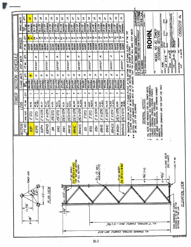
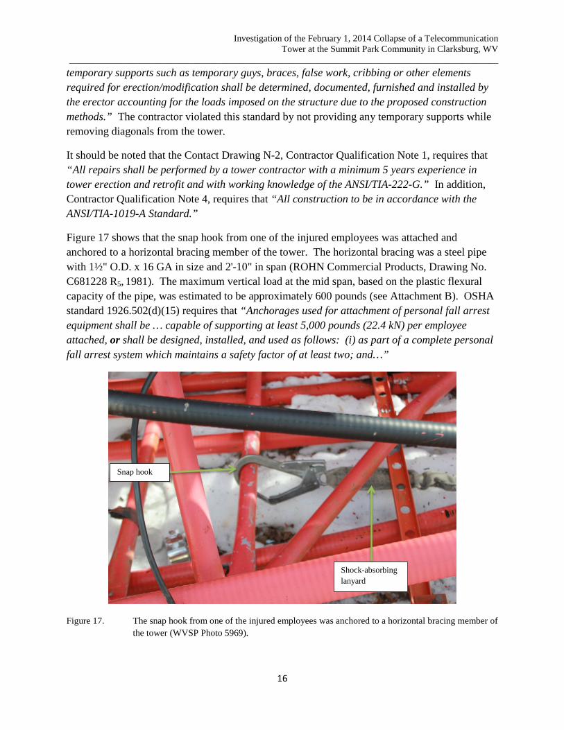
Figure 17 shows that the snap hook from one of the injured employees was attached and anchored to a horizontal bracing member of the tower. The horizontal bracing was a steel pipe with 1½" O.D. x 16 GA in size and 2'-10" in span (ROHN Commercial Products, Drawing No. C681228 R5, 1981). The maximum vertical load at the mid span, based on the plastic flexural capacity of the pipe, was estimated to be approximately 600 pounds (see Attachment B). OSHA standard 1926.502(d)(15) requires that “Anchorages used for attachment of personal fall arrest equipment shall be … capable of supporting at least 5,000 pounds (22.4 kN) per employee attached, or shall be designed, installed, and used as follows: (i) as part of a complete personal fall arrest system which maintains a safety factor of at least two; and…”
Figure 17. The snap hook from one of the injured employees was anchored to a horizontal bracing member of the tower (WVSP Photo 5969).
Snap hook
Shock-absorbing lanyard
Investigation of the February 1, 2014 Collapse of a Telecommunication Tower at the Summit Park Community in Clarksburg, WV
_____________________________________________________________________________________________
17
Figure 17 also shows that the other end of the snap hook was connected to a shock-absorbing lanyard, which was typically capable of limiting the maximum fall arrest force to approximately 900 pounds. With the minimum required safety factor of two, the anchorage for the shock-absorbing lanyard must be capable of supporting a vertical load of at least 1,800 pounds without failure. But, the horizontal bracing member had a vertical load capacity of 600 pounds, much less than the required anchorage capacity. Thus, the contractor did not comply with OSHA standard 1926.502(d)(15).
From the witness accounts and the climatological data from the Harrison/Marion Regional Airport, at the time of the collapse, there was no measureable wind at the incident site. Therefore, wind was not a causal factor of the tower collapse.
Conclusions
1. The cause of the cell tower collapse was the simultaneous removal of multiple diagonals from different faces of the tower compromising the load carrying capacity of the tower legs. No temporary supports were provided prior to the diagonal removing process.
2. The contractor did not comply with the industry standard – ANSI/TIA-1019-A, Section 2.2. Rigging Plans and Section 2.7. Temporary Supports, when removing diagonals from the tower: • No written rigging plan was established showing the manner, sequence and number of
diagonal to be removed at a time. • No qualified engineer was involved in establishing any rigging plan. • No temporary supports were provided when removing structural members.
In addition, the contractor did not comply with the industry standard – ANSI/TIA222-G, Section 16.0 Installation; by not providing any temporary supports while removing diagonals from the tower.
Thus, the contractor violated Occupational Safety and Health Act of 1970, Section 5(a)(1).
3. One of the personal fall arrest systems used by the employees was anchored to a horizontal bracing member of the tower. A shock-absorbing lanyard was used in this system. Under this condition, the maximum fall arrest force was limited to approximately 900 pounds. The minimum required anchorage capacity would need to have been approximately 1,800 pounds to achieve a safety factor of two. However, the horizontal bracing member had a capacity of 600 pounds less than the required anchorage capacity. Thus, the contractor did not comply with OSHA standard 1926.502(d)(15).
4. Wind was not a causal factor of the tower collapse.