investigation of near field inductive com - pier
TRANSCRIPT

Progress In Electromagnetics Research B, Vol. 49, 129–153, 2013
INVESTIGATION OF NEAR FIELD INDUCTIVE COM-MUNICATION SYSTEM MODELS, CHANNELS AND EX-PERIMENTS
Johnson I. Agbinya*
Department of Electronic Engineering, La Trobe University, Bundoora,Melbourne, Australia
Abstract—Near-field inductive channels created between two or moremagnetically coupled inductive nodes are studied in this paper. Peer-to-peer configurations and array architectures are discussed. The arraychannels are used for cooperative relaying with inductive methods withpotential to provide range extension and enhanced data rate access inmagnetic induction communication systems. The received power showsthe presence of the nearest neighbour interactions and the influences ofhigher order coupling from nodes two or more positions away from thereceiver. This influence causes phase changes in the communicationsystem. Four methods of exciting the antenna arrays are proposed.These are array edge excitation, center excitation, collinear arrayexcitation and multi-array excitation. Experiments with hardwarenodes show that while array edge excitation provides increased powerat the array edge, it is out performed by array center excitation whichresults to twice the power captured at the array center node comparedto the power captured at edge excited first element. We demonstrateby example that a receiver is influenced most by its neighbouring nodeson both sides and that the effects of second and third tier neighboursare relatively insignificant.
1. INTRODUCTION
Electromagnetic (EM) waves have traditionally played the leadingrole in most telecommunication systems and applications. Both theelectric and magnetic fields of an EM wave propagate together as thePoynting vector with the two vectors oriented at ninety degrees to eachother. Near an antenna in its near-field region the magnetic field is the
Received 5 December 2012, Accepted 12 February 2013, Scheduled 19 February 2013* Corresponding author: Johnson Ihyeh Agbinya ([email protected]).
130 Agbinya
dominant component while far away from the antenna in the far-fieldregion, the electric field becomes dominant. The magnetic field energyin the near-field can be acquired through mutual coupling of inductors.The power in the magnetic field decays very fast in the channel as aninverse sixth power of distance while the electric field decays as aninverse quadratic function of distance. In the far-field region of anantenna therefore, most of the energy in an EM wave is held in theelectric field.
Environmental conditions make the use of such EM waves notsuitable for communications underground (mines, tunnels, oil andgas wells) and in water. This is because of the intrinsic properties(permittivity and permeability) of these media. First in undergroundcommunications EM waves encounter at least three major problemsof high path loss, rapid changes in the channel conditions due tothe changing nature of the terrain (water and soils of varying EMattenuation regimes) and need large antennas. Under these conditions,terrestrial EM communications do not perform optimally [1–4].Changing soil characteristics with temperature and water contentcauses large bit error rates and degrades performance. Secondcommunication in coastal regions also face changing conditions due tothe dynamic environmental factors such as shallow bathymetry, waveand tidal action, acoustically reflective boundaries and marine growth.In coastal regions, reflectivity, noise and multipath effects renderconventional radio and acoustical systems significantly ineffective. Thesignal degradation sources make both acoustic and EM navigationand communication systems unreliable [5]. However many ecologicaland industrial navigation situations occur in coastal regions and manyof the mine warfare operations are performed in such environments.Third short range communication networks such as body area networksencounter large bio-impedances contributed by biological tissues whichfor safety reasons negate extended use of EM waves for communicationsand power transcutaneous power transfer. Hence a physical accesstechnology is required which help to limit and/or solve some of theproblems associated with the above terrains.
2. RELATED WORK
Magnetic induction (MI) communication is a promising alternativephysical access method to EM waves first in terms of its abilityto create a so-called secure communication ‘bubble’ [6, 7] around atransmitter. Second, it solves some or all of the problems associatedwith EM communications. In EM radio communications, the radiationresistance of a conventional antenna system must be made fairly

Progress In Electromagnetics Research B, Vol. 49, 2013 131
higher than the ground losses to ensure that strong electric field isproduced. In MI communication however, the radiation resistance ofthe antenna coils are very small and insignificant EM waves created donot propagate far. Rather a magnetic field is created by the transmitterwhich induces a sympathetic flux in the receiver coil. The sympatheticreceiver flux is proportional to the current in the transmitter loopand the inductances of the transmitter and receiver loops. The roleof the channel appears as gain reduction in the receiver power (theso-called coupling coefficient) and has a dramatic attenuating impacton the received power at long distances. The near absence of theEM field means that the magnetic field does not propagate, is quasi-static in air and in most medium it is primarily diffusive. Furthermore,the associated very low power applications means they are relativelysafe and have less impact on biological tissues with little to noheating effects. Hence they are popular in implantable hearing aidsand magnetic resonance imaging (MRI) systems. As a result theapplication of magnetic fields in medicine dates back to hundreds ofyears [22]. Near-Field Magnetic Induction Communication (NFMIC)is a wireless form of short range communication, up to 5m, usingnear field magnetic flux for data transmission [11, 12]. In reality theyoperate as proximity communication systems. They are an efficientmeans of creating secure self-powered body area networks, paymentcards, biomedical monitoring, near field mobile phones, MP3 players,body implants and many more [6, 9, 10].
Compared to other short range communication technologies suchas Bluetooth, MI is about six times more power efficient. Moreover,it promotes frequency reuse over short and long distances. It alsocontributes less interference with other existing radio frequency (RF)communication systems, because it does not have to operate inbusy 2.45 GHz region and the data needs to be communicatedwithin a person’s NFMIC ‘bubble’ [1]. A major advantage ofMIC over traditional EM RF-based systems is that the MI wavesare not generally affected by the environment. Therefore, thischaracteristic of near field magnetic induction communication makes itconsiderably advantageous over EM RF-based communication systemsin applications such as underground or underwater communications.However, the impact of path loss (a function of distance to powerof 6) is critical in NFMIC compared to RF networks. Therefore,NFMIC targets the medium capacity personal area networks with closeproximity.
A MI communication system was recently demonstratedin [6, 13, 14, 23] for underground communication in mines where theeffects of the terrain and the environment strongly reduce the perfor-

132 Agbinya
mance of RF methods but it led to poor range coverage a feature thatis suited to secure short range ‘communication in a bubble’. Therefore,in the application in [2] a magneto-inductive waveguide was used toextend the range of communications. In a magneto-inductive waveg-uide there is no need for the relay coils to be individually powered sinceeach coil induces flux to its neighbors and through that means informa-tion is carried from neighbor to neighbor until the receiver is reached.Magnetic waveguides were studied by Shamonina and Solymar [15–17].They showed that with proper terminations power losses are minimizedin the waveguide system. The impedance matching at the receiverblocks backward waves and only forward magneto-inductive waves ex-ist in the system. If discontinuities exist in the waveguide system,reflections are observed causing reduced power coupling to the load.Discontinuities in MI waveguides occur when the impedances of neigh-bouring coils are different. Hence in this paper non-reflective waveg-uides are assumed by making the links identical or using identical coilsat each node.
The application of MI techniques in remote wireless power transferhas also been studied recently in [8, 18] and the energy scavengingproperties reported by Jiang et al. [19, 20]. The authors evaluated theeffects of small loads and large loads from the communication rangepoint of view. Understandably, coupled power to the receiver load isproportional to the load and hence it is expected that smaller rangewould be obtained when the parasitic resistances of the coils are large.Recently we studied the MI communication bubble created by an MIpeer-to-peer system [6, 23] as basis for MI transceiver design. It wasshown that the size of the bubble is determined by the quality factors(Q), the efficiencies (η) and the coupling coefficient (k(x)) between thecoils. We established the basis for understanding the nature and size ofthe MI bubble. A MI bubble is defined as the sphere of communicationaround the inductive loop operating in the near-field region. Outsidethe bubble it is assumed that the flux created by the loop is nearlyzero. Outside the bubble however, the loop has remnant EM wavesand behaves as RF antenna marginally. The objective in MI systemdesign is to ensure that the vanishingly small waves are not detectableoutside the bubble and if there is to provide a means of limiting it. Theneed to couple power efficiently to the receiver is however paramountin MI systems.
Based on work by Agbinya and Masihpour in [24], Fatiha etal. [25] recently characterized the magnetic link performance ofan embedded ingestible capsule at 40 MHz with the objective ofdetermining the efficiency of magnetic systems. Also a recent briefdiscussion on inductive channel is given by Lee in [26]. Inductive

Progress In Electromagnetics Research B, Vol. 49, 2013 133
channels and link budget, therefore, remain an active area of currentinterest. In this paper we provide a models and thorough analysis ofmagnetic links and channels with the objective of helping to establishmore efficient inductive communication under different conditions andsystem configurations.
In the rest of the paper we discuss the general principles ofinductive communications in Section 3. Inductive communicationchannels are introduced in Section 4 from the waveguide model pointof view and a thorough analysis of the peer-to-peer inductive link isprovided. To allow the link performances to be assessed, Section 5provides various techniques for exciting the magnetic communicationsystem and elaborate expressions for the received power at variouspositions along the chain of nodes are provided. Simulations of theeffects of nearest neighbor interaction on array performance are givenin Sections 6 with conclusions drawn in the Section 7.
3. PRINCIPLES OF MAGNETIC INDUCTIONCOMMUNICATIONS
In magnetic communications, the MI transmitter uses typically aresonant small coil of small radius and a similar resonating coil actingas the receiver (Figure 1) [27]. The transmitter is modeled as amagnetic dipole operating at very low frequencies and hence anyelectric field created is vanishingly small and has no far field effectsand hence cannot be detected in the far field region and hence suitedto clandestine operations. The magnetic moment m (m = N · I · A)created on axis in an air core system is proportional to the numberof turns N of the antenna coil, the area A (m2) of the coil and thecurrent I (amperes) flowing through it. The magnetic moment canbe increased by deploying the coil on a magnetically permeable coresuch as a ferrite rod so that m = µrN · I · A, where µr > 1 is therelative permeability of the core material and is a strong function ofthe orientation of the coil.
Communication using magnetic field requires that the flux bemodulated and many of the conventional modulation schemes may
TX
QGT QGR
(d)kPchannel2TP
= =
=RX
Figure 1. Peer-to-peer MI communication system.

134 Agbinya
be employed depending on the application [1, 23]. The voltage whichcan be induced in the receiver coil is proportional to the magnetic fluxdensity, the area of the coil, the operating frequency and the numberof turns of the coil. This voltage can also be enhanced by laying thecoil on a magnetically permeable material with permeability µx. Theinduced voltage is
V = µx2πB ·NA · f (1)By tuning the receiver coil to resonate with the transmitter, furtherenhancement of the induced voltage is obtained. Furthermore, by usinga coil of higher Q and higher coil efficiency η, this voltage can alsobe increased while sacrificing bandwidth [2, 6, 23]. The magnetic fieldstrength developed by the transmitter decays at a rate proportionalto the inverse d to power three (1
/d3) and hence the power decay
is proportional to (1/d6). MI bubble factors were recently proposed
in [6]. While most authors assume that the size of the near fieldmagnetic induction (NFMI) bubble is the same as the edge of nearfield in [6] we have demonstrated that the two are not the same.The signal level at the near field edge is still too high and easilyavailable for interception with a sensitive instrument and [6] quantifiesthe bubble for that purpose. Intuitively, we define the magnetic bubblein terms of the sensitivity of the receiver [6]. The power transferredto a receiver load resistance RL is proportional to the transmittedpower, the quality factors of the coils, the coupling coefficients and theirefficiencies [6]. When the radius of the transmitting coil is smaller thanthe communication range (r1 ¿ x) the received power at resonance atlocation x is [6]:
Pr(ω = ω0) = PtQ1Q2η1η2k2(x)
= PtQ1Q2η1η2r31r
32(
x2 + r21
)3∼= σ
x6; r1 ¿ x (2)
where σ = PtQ1Q2η1η2r31r
32. The received power is therefore,
a decreasing function of distance to power six (6). The factorσ was defined in [6] as the distance bubble factor and quantifiesthe communication range to within a short radius centered on thetransmitter which is traditionally called the “bubble”. Although thebubble range is a function of the quality factors and coil efficiencies itis typically a couple of meters and a few centimeters for embeddedmedical devices. The fast power decay is considerably significantfor secure communications where the objectives are the security ofthe transmitter and data and the safety of the person carrying thetransceiver. The capacity of such a system was recently given by theauthors in [6, 23] and in [10]. Let d be the distance at which the received

Progress In Electromagnetics Research B, Vol. 49, 2013 135
signal power is equal to the sensitivity of the receiver Pr = PS , wherePS is the sensitivity of the receiver. This indicates that the size of thebubble is not fixed but rather is a function of the receiver sensitivity.We may also define the size of the bubble in terms of the signal tonoise ratio (SNR) of the system and defines the radius of the magneticbubble as the distance where the received signal power is equal to thenoise power (Pr = N or SNR = 1). Therefore, the system capacity atthe edge of the NFMI bubble is
C = Bff0 log2
(1 +
Prd (ω = ω0)N
)= Bff0 log2 2 = Bff0 (3)
At the edge of the bubble, no signal amplification helps as noise is alsoamplified equally so the bubble remains secure from someone outsideit. Bear in mind that the 3 dB fractional bandwidth B is defined purelyby the Q of the coils and the centre frequency [10], where
Bf =B
f0=
1
Q1; if Q1 > Q2
1Q2
; if Q2 > Q1(4)
Thus for large capacity, the bandwidth of the system must be large.However, unlike inductive wireless power transfer that requires large Q,inductive communication systems are favoured by small quality factorsso as to maximize Bf . By letting Q1 = Q2 = Q in Equation (4), thisexpression reduces to Bf = 1/Q and the capacity at the edge of thebubble (assuming the SNR = 1 there)
C = Bff0 = f0/Q (5)is determined exclusively by the Q-factors of the coils and the resonancecentre frequency. For a resonance frequency in the ISM band of13.56MHz and Q = 40, this capacity is approximately 339 kbps. Thecapacity at the edge of the bubble is directly proportional to theresonant frequency. The higher Q is, the lower the capacity at theedge of the bubble. This paradox is the major benefit of NFMI. Theperformance should, therefore, be evaluated in terms of the efficiency ofthe communication bubble. A typical magnetic induction device drawsas low current as 7mA to transfer voice or data over a couple of meters.To their advantage magnetic induction communication systems are notgenerally affected by the environment. From the MI power equation theeffect of the environment is given by the permeability of the materialsin the link and source (sink). The permeability of the medium canbe used to advantage to amplify the signal power in the link. Thusparamagnetic and ferromagnetic channels will strengthen the magneticfield from the transmitter to the receiver.
Fading, multipath propagation, interference and noise whichplague electromagnetic (EM) systems are not problems in MI systems

136 Agbinya
but rather one of the main problems is how to improve upon therapid decline in MI power due to the inverse sixth power decay withrange. Current literature is devoid of the performance evaluation ofMI technology from a commercial hardware point of view. RecentlyFreeLinc [7] marketed MI radios of very short range typically around1.5m.
4. MI COMMUNICATION CHANNELS
The Section 3 describes simple peer-to-peer systems. Similarwork is reported in [2] by Sun and Akyildiz. Figure 2 shows thegeneral framework for magnetic waveguides as a chain of resonantloops [16, 17, 21]. The source loop transmits information and this isrelayed by the relaying nodes until the signal reaches the receiver. Wenow show that the model in [2] is similar to the Agbinya-Masihpourmodel [6, 23] if a common framework is used to compare them byestablishing a common formalism. The common formalism defines thefollowing parameters. The efficiencies of the coils are:
η = RS/RS + RL∼= 1 or RS À RL (6a)
In Figure 2 for convenience we have combined the resistances asRR = RS + RL. The quality factors at the transmitter and receiverare
QT = ωLT /RLT and QR = ωLR/RLR (6b)
ss
Transmitter Relaying nodes
x
r
d
US
R1RT
RnRR
LTLR
L1 Ln
M M
Transmitter ReceiverRelay 1 Relay n
M
Figure 2. Magnetic waveguide and circuit model.

Progress In Electromagnetics Research B, Vol. 49, 2013 137
The self resistances of the transmitter and receiver coils of radius rare usually very small and given as RLT = Rt = 2π · rT NT R0 andRLR = Rr = 2π · rRNRR0 respectively.
By substituting these in Equation (6b) when the length l =2π · r ·N À 0.9r, NT = NR = N , then
L = µA ·N2/(l + 0.9r);then LT ≈ 0.5µrT ·NT and LR ≈ 0.5µ · rR ·NR (6c)
Therefore, when the quality factors of the transmitter and receiver areequal we have shown in [1] that the coupling coefficient also is.
k2 (d) =µ2A2
R · r4T
4 · LT LR
(d2 + r2
T
)3 =π2r3
T r3R
NT NRd6(6d)
QT = ωµ/4π ·R0T and QR = ωµ/4π ·R0R. Therefore, the receivedpower is
PR = PT QT QRηT ηRk2 (d) = PT Q2k2 (d) (7)
This equation models two inductive antennas with gain Q and path lossgiven by k2(d) as shown in the Figure 1. This figure is fundamentalfor the peer-to-peer MI nodes systems in general. This commonformalism allows us to re-write the model of Equation (2) when we setη1 = η2 = 1. Therefore, the traditional Agbinya model (AM) [1, 23]can be written as:
PR =ω2µ2
16π2R20
· r3T r3
Rπ2PT
NT NRd6=
ω2µ2r3T r3
RPT
16R20NT NRd6
= Q2k2 (d) PT (8)
4.1. Magnetic Waveguide Link: Model 1
To compare the model in [1] with the model in [2], we derive the linkbudgets for both using the received power in the standard case definedas
PR
PT=
ωµ ·NRr3T r3
R
16R0d6=
ωµ
4πR0
ωµ
4πR0
π2r3T r3
R
NT NRd6
NT N2R
ωµ
=(
NT N2R
ωµ
)Q2k2 (d) (9)
The link budget equations for the two cases become: (d = 10β wherefor the AM case the link budget Equations (10) and (11))
βAM =
PT (dBm)−PR(dBm)+20·logµ+20·logω+30log(rTrR)
− [10 · log 16 + 20 · log R0 + 10 · log NT NR]60
(10)

138 Agbinya
dAM = 10PT (dBm)−PR (dBm)+20·log ω+30 log(rTrR)
60
×1020·log µ−10·log 16−20·log R0−10·log NT NR
60 (11)
The major limitation of MI communication is its rapid power decayand thus short range typically a couple of meters from the transmitterand therefore, unsuitable for applications such as wireless local areanetworks at larger range. Magneto-inductive waveguides have recentlyemerged as a method of extending the range of MI communicationssystems. We therefore propose a link budget for n section MIwaveguide. Sojdehei et al. [5], Syms et al. [15], Shamonina [16], andKalinin et al. [17] have established some of the theories for the MIwaveguide used in this section. A peer-to-peer ‘waveguide’ is wellanalyzed and discussed by Agbinya et al. in [2, 6, 23]. Consider also themodel in [2] based on our proposed framework in this paper. In doingso, we insert the defining equations in the framework in Equations 6(a)–(d). The ratio of the received power to the transmitted power is givenby the expression [1, 2]:
PR
PT≈ ω2µ2NT NRr3
T r3R sin2 α
8d6· 14R0
(2R0 + 1
2jωµNT
) (12)
In this equation, R0 is the per unit resistance of the coils. All the othervariables retain their usual meaning and the angle sin(α) originatesfrom integration of the magnetic potential of a magnetic dipole inEquation (6) in [2]. By assuming a low resistance loop, high signalfrequency and large number of turns in the transmitter and receivercircuits (R0 ¿ ωµNT ) [2] the power ratio reduces to:
PR
PT≈ ωµNRr3
T r3R sin2 α
16R0d6(13)
This model supports only peer-to-peer communication and does notdeliver maximum power to the receiver load due to lack of resonancebetween the receiver and transmitter. For range extension andmaximum power transfer, resonant relays with inductive waveguideare employed.
A MI waveguide consists of n sections which relay data as inFigure 2. The transmitter couples energy to the first coil near it andthat coil couples energy to coil on its right and this process repeats untilthe receiver is reached. Thus the link Model 1 and range expression

Progress In Electromagnetics Research B, Vol. 49, 2013 139
are derived from the channel model equation in [2] and are:
βM1 =pT (dBm)− PR (dBm) + 10 · log µ + 10 · log NR
60
×[30 log (rT rR)− 10 · log 16− 20 · log R0
60
](14)
The communication range is
dM1 = 10pT (dBm)−PR (dBm)+10·log µ+10·log NR
60
×10+30 log(r
TrR)−10·log 16−20·log R0
60 (15)In the simulations to follow we use rT = 2.5 cm, rR = 1.5 cm,NT = NR = 10 and R0 = 0.0216Ω/cm. The communication distance is0 ≤ d ≤ 6m and the frequencies are 13.56 MHz, 300MHz and 900 MHz.The ratio of the received powers for the two models is
PR,AM
PR,M1=
ωµ
N2RNT R0
(16)
4.2. Magnetic Waveguide Link: Model 2
MI waveguide can be efficient in underground wireless communicationsystems if each magnetic coil is used as a relaying node for sending datawithout power consumption; by connecting a capacitor to each loop,maximum power is transferred at resonance. With this a path lossmodel is proposed and relates the transmitted power and the receivedpower to the system parameters (permeability, per unit resistance ofthe wire of the transmitter and receiver coils, number of turns, theirradii, transmitting frequency and communication range as given in [3]).
At resonance the impedance of each loop is resistive and theresonance frequency is ω0 = 1
/√LC and ω2 = 1/LC. This allows
the value of the capacitor required for resonance at each relaying nodeto be determined for an inductor of radius ‘a’ as
C =2
ω2N2µ · π · a (17)
Therefore, when the capacitor is in circuit, the path loss expression ina magnetic waveguide is:
PR
PT=
ω2N2µ2r3T r3
R
4x62R0
(4R0+ ω2N2µ2r3
T r3R
4x62R0
)×[j
[4R0
ωµN
(x
a
)3+
ωµN
4R0
(a
x
)3]−1
]2n
(18)
The variable x is the separation between any two sections of the MIwaveguide. Thus the total communication range d is divided into n+1

140 Agbinya
sections of length x, or d/x = (n + 1). The imaginary term dissolvesto a real value because of the exponent 2n in Equation (18). The pathloss is a real positive number for even n and for odd values of n hasa negative value. Thus when the traditional magneto-inductive waveis present a positive value is obtained. A negative value indicates thepresence of an evanescent wave with sign changes [21]. To illustrate thebehavior of the MI waveguide the path loss expression is simplified intothe so-called AM2 link budget and provides insight into the achievablerange. By using the expressions for the Q factors, we rewrite the pathloss equation as a product of two terms:
PR
PT= P1P2n (19)
P1 =ω2N2µ2r3
T r3R
4x62R0
(4R0 + ω2N2µ2r3
T r3R
4x62R0
)
=ωµ
4πR0· ωµ
4πR0· N2π2k2 (x)(
2 + ωµ4πR0
· ωµ4πR0
·N2π2k2 (x)) (20a)
P1 =QT ·QRN2π2k2 (x)
(2 + QT ·QR ·N2π2k2 (x))(20b)
By approximating k2 (x) ≈ r3T r3
Rx6 (similar to neglecting ∆d in the AM
model), the second term is:
P2n=
[j
[4R0
ωµN
(x
a
)3+
ωµN
4R0
(a
x
)3]−1
]2n
=(QT ·QRN2π2k2(x)
)n
[j
(1+
ω2µ2N2π2
(4R0π) (4R0π)k2(x)
)−1]2n
(21a)
Therefore
P2n =(QT ·QRN2π2k2 (x)
)n[
j
(1 + QT ·QRN2π2k2 (x))
]2n
(21b)
Therefore, the path loss equation becomes
PR
PT=
QT ·QRN2π2k2 (x)(2 + QT ·QR ·N2π2k2 (x))
(QT ·QRN2π2k2 (x)
)n
×[
j
(1 + QT ·QRN2π2k2 (x))
]2n
(22)

Progress In Electromagnetics Research B, Vol. 49, 2013 141
Define β = QT QRN2π2k2 (x) as the section path loss. The waveguidepath loss is, therefore, given by the expression:
PR
PT=
β · βn
(2 + β)
[j
(1 + β)
]2n
=(
βn+1
(2 + β)
)(1
(1 + β)
)2n
ejπn (23)
The phase term in Equation (23) accounts for the presence of twotypes of waves in the waveguide the traditional magneto-inductivewave and an evanescent wave whose modulus decays exponentially andchanges signs between adjacent elements [21]. Syms et al. [21] have alsoexplained the presence of higher-order interactions on the traditionalMI wave causing the phase change and negative amplitude for odd n.For weak coupling between the coils, k2(x) ¿ 1, β ¿ 1 and notingthat exp(jπn) = ±1 the above expression simplifies to
PR
PT=
βn+1
2(24)
In this situation, the flux developed by the transmitter is weakly linkedto the receiver coil and the overall waveguide power is a geometricproduct of the section path losses. For strong coupling between thecoils k2 (x) ≈ 1, and β À 2 and the expression reduces to:
PR
PT=
βn
2
[j
β
]2n
(25)
For n = 0 we have the simple peer-to-peer MI system path lossequation. When rT = rR = x, we have k(x) = 1. The couplingcoefficient cannot be more than unity or rT ·rR cannot be greater thanthe section length (usually rT · rR ≤ x2). The inequality rT · rR > x2
is an impossible situation as it is not possible that the receiver collectsmore flux than all the flux created by the transmitter. For n = 0 andβ is unity the received power is a third of the transmitted power andwe have the same result as in [2]:
PR
PT=
13
(12
)2n
(26)
This means that β = QT QRN2π2k2 (x) or the equation required fordetermining optimum power transfer between the sections is a functionof the number of turns, the coupling coefficients and the quality factorsof the coils, thus quantifying the received power well.
4.3. One Section Peer-to-peer (Line of Sight)
The power relationship in a one-to-one transmitting system is of greatinterest as it applies to many applications which do not require range

142 Agbinya
extension. When n = 0 (reduced model) the peer-to-peer system haspath loss equation:
PR
PT=
QT ·QRN2π2k2 (x)(2 + QT ·QR ·N2π2k2 (x))
(27)
i) When QT ·QR ·N2π2k2 (x) À 2 the power equation approaches thevaluePR/PT ≈ 1. This is a strong coupling case and the distancebetween the transmitter and receiver is close to zero, d → 0. Thereceived powers in most communication systems are usually notequal to the transmitted power due to losses in the channel andthe transceiver circuitry.
ii) When
QT ·QR ·N2π2k2 (x) = 2; PR/PT = 1/2 (28)
We also have a relatively strong coupling case. This approximationpromises that 50% the transmitted power can be delivered to theload. This level of efficiency is achievable with current inductivesystems.
iii) When QT ·QR ·N2π2k2 (x) ¿ 2, or k2 (x) is small (weak coupling),a more practical situation, then
PR
PT≈ QT ·QRN2π2k2 (x)
2(29)
Even by using different assumptions, we arrive at a familiar expression.The reduced model and the AM models are equivalent (to within aconstant multiplier). Thus the Agbinya-Masihpour model and Sun [2]model are identical and correctly model MI communications systems.
4.4. Multiple Sections Waveguide (Chain Network)
In this section N loop waveguide is investigated.i) When the approximation QT · QR · N2π2k2 (x) À 2 is used, the
expression for the multi-section waveguide simplifies to:
PR
PT≈ (
QT ·QRN2π2k2 (x))n
[j
(QT ·QRN2π2k2 (x))
]2n
(30)
ii) However when QT ·QR ·N2π2k2(x) = 2, the approximation gives:
PR
PT=
2n
4
[j
3
]2n
(31)

Progress In Electromagnetics Research B, Vol. 49, 2013 143
For n sections, the communication distance d = n · x, the linkbudget equation is
d = 10(PT (dBm)−PR (dBm)−6−6.541n) (32)
iii) When QT ·QR ·N2π2k2 (x) ¿ 2 the power equation simplifies to
PR
PT≈ Real
(12
(QT ·QRN2π2k2 (x)
)n+1ejπ·n
)(33)
This expression is truly the (n + 1) section power and the receivedpower is always less than the transmitted power.
5. EXCITATION METHODS
Array excitation defines how the input signals are introduced tothe transmitters to be coupled to the receivers. Four methods areproposed.
5.1. Array Edge Excitation
In the array edge excitation (AEE), the relay nodes are edge excitedby lining up the transmitter directly opposite the relay node 1 asshown in Figure 3. The transmitter axis is at 90 degrees to thearray axis. The transmitter coil has a radius of 6 mm and the receivercoils have identical radius of 3.5mm with each one wound on a ferriteformer. Array element n is inclined by an angle θnwith respect to the
Figure 3. Array edge excited SIMO system.

144 Agbinya
transmitter and the length of the array is l. The diagonal distancelinking the transmitter and receiver n is dn and n is the node index.Generally
d2n = d2 + l2n; ln =
n−1∑
j=1
xj . (34)
In the following analysis, nearest neighbor coupling (NNC) concept inwhich node n is influenced by only nodes (n − 1) and (n + 1) and noother mutual induction from far away nodes is experienced is used. Itis also extended to when more than one node on either side of a nodeinfluence it and their significances are quantified. The power receivedby a node n (section) without influence is given by the expression:
PRn
PT≈ Q2N2π2k2 (dn) cos6 θn
2(35)
This power decays with the sixth power of the misalignment anglebetween a receiver and transmitter causing significant reduction in thereceived power and is a cause of reduced optimum power reception inMI systems. Figure 3 consists of seven receiving nodes and except fornode n = 1, all the other nodes are misaligned by some angle from thetransmitter. Using NNC, node 7 at the edge is influenced by node sixonly and its total power is:
PR7
PT≈ Q2N2π2k2 (d7)cos6θ7
2+
Q2N2π2k2 (d6) cos6 θ6
2×Q2N2π2k2(x)
2
=Q2N2π2
2
(k2 (x)
Q2N2π2k2 (d6) cos6 θ6
2+ k2 (d7) cos6 θ7
)
= α · β · [k2 (d6) cos6 θ6 + β−1k2 (d7) cos6 θ7
](36)
Similarly the power received by node 6 is
PR6
PT≈ Q2N2π2k2(d6)cos6θ6
2+
Q2N2π2k2(d7)cos6θ7
2×Q2N2π2k2(x)
2
+Q2N2π2k2 (d5) cos6 θ5
2× Q2N2π2k2 (x)
2= α · β · [k2(d5) cos6 θ5 + β−1k2(d6) cos6 θ6 + k2(d7) cos6 θ7
](37)
where α = Q2N2π2
2 and β = Q2N2π2k2(x)2 . In general the receiver n
power is:
PRn = αβ · [k2(dn−1) cos6 θn−1 + β−1k2 (dn) cos6 θn
+k2 (dn+1) cos6 θn+1
] · PT (38)
Progress In Electromagnetics Research B, Vol. 49, 2013 145
In practice the coupling coefficients k(x) are small values and the powerreceived from the nearest neighbours is, therefore, small comparedwith the direct signal between the transmitter and a receiver. Whenxn−1 6= xn 6= xn+1, and using α only the general equation may also bewritten as:
PRn = α2 · [k2 (xn−1) k2 (dn−1) cos6 θn−1 + α−1k2 (dn) cos6 θn
+k2 (xn+1) k2 (dn+1) cos6 θn+1
] · PT (39)
Let N nodes on either side of the receiver have influence on its receivedpower. For such a case the total received power at node n becomes:
PRn =N∑
j=0
αj+1
[k2 (dn−j) · cos6θn−j
j∏
i=0
k2(xn−i)
+k2(dn+j)·cos6θn+j
j∏
i=0
k2(xn+i)
]·PT k2(xn) = 1/2 (40)
When k2 (xn) = 1/2, the above equation is general for all n.
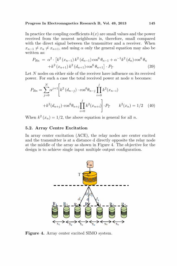
5.2. Array Centre Excitation
In array center excitation (ACE), the relay nodes are center excitedand the transmitter is at a distance d directly opposite the relay nodeat the middle of the array as shown in Figure 4. The objective for thedesign is to achieve single input multiple output configuration.
Figure 4. Array center excited SIMO system.

146 Agbinya
The power received by the receiver n with NNC consideration isgiven by the expression:
PRn = α2 · [k2 (xn−1) k2 (dn−1) cos6 θn−1
+k2 (xn+1) k2 (dn+1) cos6 θn+1 + α−1k2 (dn) cos6 θn
] · PT (41)In a symmetrical arrangement of the array elements with respect tothe transmitter location, the following conditions hold for a receiver n:θn−1 = θn+1; xn−1 = xn+1 and dn−1 = dn+1. Hence
PRn = α2 · [2k2 (xn+1) k2 (dn+1) cos6 θn+1 + α−1k2 (dn) cos6 θn
] · PT (42)For multi-neighbour interaction by N nodes on either side, the receivedpower by node n is:
PRn = α · k2 (dn) · cos6 θn
+2N∑
j=0
αj+1
[k2 (dn+j) · cos6 θn+j
j∏
i=0
k2 (xn+i)
]· PT (43)
The gain obtained by ACE is significant if the nodes cooperate andreinforce each other. When the array is centre excited and the nodesare not symmetrically placed with respect to the transmitter, thereceived power is:
PRn =α · k2 (dn) · cos6 θn +N∑
j=0
αj+1[k2 (dn+j)
· cos6θn+j
j∏
i=0
k2(xn+i)+k2(dn−j)·cos6θn−j
j∏
i=0
k2(xn−i)
]·PT (44)
When the array is not perpendicular to the excitation source,Equation (44) holds. However, the values of dn which reflect the lateralshift of the array with respect to the excitation should be used.
5.3. Collinear Array Excitation
In the collinear array excitation (CAE), the transmitter axis is collinearwith the array axis and the nodes form a linear chain network. All thearray elements including the transmitter are separated from each otherby distance x. A previous node serves as the exciter for its neighborand the power received by node n is obtained recursively as
PR1≈Q2N2π2k2 (x)2
PT ;
PR2≈Q2N2π2k2 (x)2
PR1 =(
Q2N2π2k2 (x)2
)2
PT
(45)

Progress In Electromagnetics Research B, Vol. 49, 2013 147
The power received by node n is thus given as
PRn≈Q2N2π2k2 (x)2
PR(n−1) =(
Q2N2π2k2 (x)2
)n
PT ;
PRn≈(
12
)n+1 (Q2N2π2k2 (x)
)n+1PT
(46)
The last equation is for (n+1) sections. The power expression is similarto the MI waveguide and has no phase term as in the original MIwaveguide equation. These equations show that CAE power transfercapability is very poor for nodes which are not near the transmitterbecause of being shielded by other nodes from the effects of the receiverleading to increasingly weak coupling of flux the farther away the nodeis from the transmitter.
5.4. Multiple Array Excitation
In the multiple array excitation (MAE) several arrays are usedconcurrently as in Figure 5 and each array is excited separately. Themultiple arrays open up several options for array deployment. Theremay be only an excitation, or each array may be excited or only asubset of the array is excited.
Figure 5. Multiple array excitation (MAE).

148 Agbinya
Assume that the nodes in each array are arranged in a regularmanner, equidistant (may not be so all the time) from each otherand excited as in CAE. The arrays are of the same length. We alsoassume that the distance between the arrays is large enough to preventneighbouring arrays from interfering with each other. The arrays are ofinfinite length with no reflections. In a multi-array system, the receivern taps its signals from each array at location n.
Thus the receiver is separate from the system of arrays. Thereceived signal by receiver n when the transmitter excitations are equalis given by the expression:
Pn =M∑
j=1
PRj = PT
M∑
j=1
(12
)nj (Q2N2π2k2 (dnj)
)nj cos6 (θnj) (47)
where M is the number of arrays with index j and n is the nodelocation inside each array where flux is tapped into the receiver. Thisrelay system consists of M transmitters each serving n nodes (a totalof M ×N nodes). A receiver listens to M main sources, one from eacharray provided the transmitters are in its neighbourhood. The distancebetween array elements is 2x. The MAE system is suitable for multi-channel MI communication and may require coding of channel signalsto enable easy separation at the receiver. It may also use OFDMsystem.
6. SIMULATION AND EXPERIMENTAL RESULTS
We conducted various experiments with both hardware and softwarewhen the receivers are located within the near field region of thetransmitter. Multiple relay nodes were designed and arranged in achain network. They were deployed on a wooden holder and each nodeis a stand alone with no physical connections to its neighbours. Onetransmitter was also designed using a 151µH inductor connected toa 39 µF capacitor and excited with an input at 2.65MHz frequency.Figure 3 shows the hardware set up for the experiments. Using AEEarchitecture the received power profile was measured with a softwareoscilloscope attached to a laptop. An exponentially decaying powerprofile with a maximum value at the coil at the array edge oppositethe transmitter was observed. When the transmitter input voltage is30mV and the receiver node at 2.3 cm from it, the received voltage is520mV, a gain of 17.3 at bore site (Figure 6). The receiver array wasmoved to 5 cm from the transmitter still within the near-field regionof the transmitter. The received voltage at bore sight was measuredto be 46 mV, a voltage gain of 1.53. The receiver array was moved

Progress In Electromagnetics Research B, Vol. 49, 2013 149
Figure 6. Received power by nodes 1 to 5 in AEE.
Figure 7. Array power gain profile.
further to 7 cm from the transmitter. The received voltage at boresight is 27mV, a gain of 0.9. Thus the received power decreases veryfast as the receiver is moved away from the transmitter. In Figure 7,the receiver arrays were located at 2.3 cm, 5.0 cm and 7 cm from thetransmitter. Very high induced power was recorded at distances veryclose to the transmitter and decrease rapidly as the array is movedaway to 5 cm and then to 7 cm.
Despite the apparent gains provided by the ACE arrangement theintention of this section is to show that significant gains are obtainedusing NNC and the advantages in using multiple neighbour interactionbecome more and more insignificant the further away the nodes are

150 Agbinya
from the receiver. This is due to shielding by other nodes on bothsides and also highly reduced mutual inductance between the nodes.For example, let d = 5 m; xj = 10 m; rT = 10 cm and rR = 5 cm. Then
d21
= d2+x21 =25 · 104+106 cm2 =125·104 cm2;
cos θ1 =5√125
; cos6 θ1 =(
1125
)
k2 (d) ≈ r3T r3
R
d6=
1(125)2 · 106
;
k2 (dn+1) ≈ r3T r3
R
d61
=103 · 53
[100
(√125
)]6 =1
109 (125)2;
k2 (xn+1) ≈ r3T r3
R
x6n+1
=103 · 103
(1000)6=
11012
Let the transmitter and receiver coils have Q = 100 and turns N = 10,the power received from first neighbour is about
∆P =Q2N2π2k2 (dn+1) k2 (xn+1) · cos6 θ1
Pn
=
(Q2N2π2
)2k2 (dn+1) k2 (xn+1) cos6 θ1
Q2N2π2k2 (d)
=106π2
109 (125)21
1012×1012 (125)2 · 1
125=
π2
(125) 103≈ 1
125% (48)
Thus the power contributed by a nearest neighbour in this case is about(1/125)% of the direct power received by node n from the transmitter.The two nearest neighbours contribute less than (2/125)% extra power.Therefore, the effects of remote neighbours are mostly insignificant.Hence we can safely ignore the influences of neighbouring nodes beyondthe first one on both sides. Nearest neighbours will have more influenceif coils of large Q and with more turns are deployed as neighbours. Thereceived power profile with ACE is parabolic with peak centered at themiddle coil. With a transmitter input voltage of 30mV and receiverarray located at 2.3 cm from it, the highest received voltage is 1000 mV(1 volt!), an impressive voltage gain of 33.3 at bore site (Figure 7). Thereceiver array was moved to again to 5 cm from the transmitter, and thereceived voltage at bore sight is 120 mV, a gain of only 4. The receiverarray was moved once more further to 7 cm from the transmitter, andthe received voltage at bore site is 40 mV, a gain of 1.33. In general,despite the 6th power of distance power decrease for the transceivers,the received power at a point can be increased by using an array ofreceivers.

Progress In Electromagnetics Research B, Vol. 49, 2013 151
7. CONCLUSIONS
We have provided a detailed analysis of magneto-inductive channelsand link budgets showing that nearest neighbour interaction plays apart in the received signals in waveguide systems. In the relay systems,we have also shown that only first nearest neighbours on either sidesof the node have the most significant effect on it. This influence canbe beneficial. Various forms of array excitations are used showingthat array centre excitation is optimum in terms of all the arraysstudied in the paper. Theoretical analyses were justified with realisticexperimental demonstration.
REFERENCES
1. Agbinya, J. I., Principles of Inductive Near Field Communicationsfor Internet of Things, River Publishers, Denmark, 2011,ISBN: 978-87-92329-52-3.
2. Sun, Z. and I. F. Akyildiz, “Underground wireless communicationsusing magnetic induction,” Proc. IEEE ICC, 1–5, 2009.
3. Akyildiz, I. F. and E. P. Stuntebeck, “Wireless undergroundsensor networks: Research challenges,” Ad Hoc Networks Journal,Elsevier, Vol. 4, 669–686, Jul. 2006.
4. Li, L., M. C. Vuran, and I. F. Akyildiz, “Characteristics ofunderground channel for wireless underground sensor network,”Proc. Med-Hoc Net, Corfu, Greece, Jun. 2007.
5. Sojdehei, J. J., P. N. Wrathall, and D. F. Dinn, “Magneto-inductive (MI) communications,” Proc. MTS/IEEE Conferenceand Exhibition (OCEANS), 513–519, Nov. 2001.
6. Agbinya, J. I., N. Selvaraj, A. Ollett, S. Ibos, Y. Ooi-Sanchez, M. Brennan, and Z. Chaczko, “Characteristics of themagnetic bubble ‘Cone of Silence’ in near-field magnetic inductioncommunications terminals,” Journal of Battlefield Technology,Vol. 13 No. 1, 21–25, Mar. 2010.
7. FreeLinc, FreeLinc Products, accessed Mar. 3, 2009,http://www.freelinc.com/products/.
8. Sauer, C., M. Stanacevic, G. Cauwenberghs, and N. Thakor,“Power harvesting and telemetry in CMOS for implanted devices,”IEEE Trans. on Circuits and Systems — I: Regular Papers,Vol. 52, No. 12, 2605–2613, Dec. 2005.
9. Galbraith, D. C., M. Soma, and R. L. White, “A wide-bandefficient inductive transdermal power and data link with coupling

152 Agbinya
insensitive gain,” IEEE Transactions on Biomedical Engineering,Vol. 34, No. 4, 265–275, Apr. 1987
10. Jiang, H. C. and Y. E. Wang, “Capacity performance of aninductively coupled near field communication system,” Proc.IEEE International Symposium of Antenna and PropagationSociety, 1–4, Jul. 5–11, 2008.
11. Evans-Pughe, C., “Close encounters of the magnetic kind,” IEEReview, 38–42, May 2005.
12. Bansal, R., “Near field magnetic communications,” IEEEAntennas and Propagation Magazine, Vol. 46, No. 2, 114–115,Apr. 2004.
13. Lee, K. and D.-H. Cho, “Adaptive tuning method for maximizingcapacity in magnetic induction communication,” Proc. IEEE ICC,4310–4313, 2012.
14. Akyildiz, I. F., Z. Sun, and M. C. Vura, “Signal propagationtechniques for wireless underground communication networks,”Physical Communication 2, Elsevier, 167–183, 2009
15. Syms, R. R. A., E. Shamonina, and L. Solymar, “Magneto-inductive waveguide devices,” Proceedings of IEE Microwaves,Antenna and Propagation, Vol. 153, No. 2, 111–121, 2006.
16. Shamonina, E., V. A. Kalinin, K. H. Ringhofer, and L. Solymar,“Magneto-inductive waveguide,” Electron. Letters, Vol. 38, No. 8,371–373, Apr. 11, 2002.
17. Kalinin, V. A., K. H. Ringhofer, and L. Solymar, “Magneto-inductive waves in one, two and three dimensions,” Journal ofApplied Physics, Vol. 92, No. 10, 6252–6261, 2002.
18. Kopparthi, S., “Remote power delivery and signal amplificationfor MEMS applications,” MSc. Thesis, Andhra University, India,Dec. 2003.
19. Jiang, B., J. R. Smith, M. Philipose, S. Roy, K. Sundara-Rajan,and A. V. Mamishev, “Energy scavenging for inductively coupledpassive RFID systems,” Instrumentation and MeasurementTechnology Conference, Ottawa, Canada, May 17–19, 2005.
20. Jiang, B., J. R. Smith, M. Philipose, S. Roy, K. Sundara-Rajan,and A. V. Mamishev, “Energy scavenging for inductively coupledpassive RFID systems,” IEEE Trans. on Instrumentation andMeasurement, Vol. 56, No. 1, 118–125, Feb. 2007
21. Syms, R. R. A., O. Sydoruk, E. Shamonina, and L. Solymar,“Higher order interactions in magneto-inductive waveguides,”Metamaterials, Vol. 1, 44–51, 2007.
22. Grace, R. J., “Bio magnetic energy in pain relief and healing,”

Progress In Electromagnetics Research B, Vol. 49, 2013 153
Proc. 2nd International Conference on Bioelectromagnetism, 143–144, Melbourne, Australia, Feb. 1998.
23. Agbinya J. I. and M. Masihpour, “Power equations and capacityperformance of magnetic induction communication systems,”Wireless Personal Communications, Vol. 64, No. 4, 831–845,Springer, Jun. 2012.
24. Agbinya, J. I. and M. Masihpour, “Near-field magnetic inductioncommunication link budget: Agbinya-masihpour model,” Proc. ofIB2Com, Malaga, Spain, Dec. 15–18, 2010.
25. Fatiha, E. H., G. Marjorie, S. Protat, and O. Picon, “Link budgetof magnetic antennas for ingestible capsule at 40 MHz,” ProgressIn Electromagnetic Research, Vol. 134, 111–131, 2013.
26. Lee, K. and D.-H. Cho, “Adaptive tuning method for maximizingcapacity in magnetic induction communication,” Proc. IEEE ICC,4310–4314, 2012.
27. Agbinya, J. I., “A magneto-inductive link budget for wirelesspower transfer and inductive communication systems,” ProgressIn Electromagnetics Research C, Vol. 37, 15–28, 2013.