investigation of instabilities in a folded- waveguide ... · waveguide sheet-beam twt h. s....
TRANSCRIPT

4266 IEEE TRANSACTIONS ON ELECTRON DEVICES, VOL. 64, NO. 10, OCTOBER 2017
Investigation of Instabilities in a Folded-Waveguide Sheet-Beam TWT
H. S. Sudhamani, Jyothi Balakrishnan, and S. U. M. Reddy, Member IEEE
Abstract— Particle-in-cell (PIC) simulation was used foranalyzing the instabilities due to zero-drive oscillations ina 220-GHz folded-waveguide (FW) traveling-wave tube. Theequivalent circuit analysis based on the transmission lineapproach was used for the parametric design of the FWstructures (FWSs) with circular and rectangular (horizontaland vertical) beam holes. Experimental validations withreference to the dispersion and interaction impedance char-acteristics were carried out on a scaled model of the slowwave structure in the Ku band. The oscillations observed invarious configurations of the FWS were subsequently ana-lyzed using the Brillouin diagram. The FWS with horizontal-rectangular beam hole was found to have a better immunityto instability compared to the other two configurations.
Index Terms— Beam configurations, folded-waveguide (FW) traveling-wave tubes (TWT), instabilities,sheet-beam TWT, zero-drive oscillations.
I. INTRODUCTION
FOLDED-WAVEGUIDE traveling-wave tubes (FWTWT)employing folded-waveguide slow wave struc-
tures (FWSWSs) are becoming increasingly importantdue to their suitability for high-frequency operation extendingto terahertz [1]–[6]. A typical FWSWS consists of twosemicircular E-plane rectangular waveguide bends and twostraight rectangular waveguide sections having beam holesat the center of each straight waveguide sections. A typicalperiod of an FWSWS having three types of beam-holecross sections (circular, horizontal-rectangular, and vertical-rectangular) is shown in Fig. 1. There exists an inherentphase reversal of the axial electric field (along the beamaxis) between the successive beam crossings similar to thatoccurring in a coupled-cavity slow wave structure (CC-SWS)operating in the forward space-harmonic mode. The FWSWSalso has the passband and stopband characteristics similar tothat in a CC-SWS. Thus, an FWG-SWS may be consideredto have an analogous “cavity passband” and “slot passband”
Manuscript received December 28, 2016; revised February 20, 2017,March 24, 2017, April 28, 2017, and July 12, 2017; acceptedJuly 21, 2017. Date of publication August 14, 2017; date of current versionSeptember 20, 2017. This work was supported by the Defence Researchand Development Organisation, Ministry of Defence, Government ofIndia. The review of this paper was arranged by Editor L. Kumar.(Corresponding author: H. S. Sudhamani.)
H. S. Sudhamani and S. U. M. Reddy are with the Microwave TubeResearch and Development Centre, Bangalore 560013, India (e-mail:[email protected]).
J. Balakrishnan is with Bangalore University, Bangalore 560056, India.Color versions of one or more of the figures in this paper are available
online at http://ieeexplore.ieee.org.Digital Object Identifier 10.1109/TED.2017.2736065
Fig. 1. Typical schematic of a period of the FWS with (a) circular beamhole, (b) horizontal-rectangular beam hole, and (c) vertical-rectangularbeam hole.
as in a CC-SWS, a consideration useful for analyzing thephenomenon of instability in an FWTWT, as will be seenin subsequent sections. However, a serious limitation of anFWSWS is its low interaction impedance. A popular schemeof enhancing the on-axis average interaction impedance andalso enhancement of interaction efficiency through higherbeam current is often used by employing a sheet electronbeam for RF interaction [7]–[9].
In a sheet-beam device, a circular beam is typically recon-figured to a rectangular cross section having its width as twicethe diameter and thickness/height as half the diameter of thecircular beam thereby offering the possibility of an enhancedcross-sectional area by around 27%. Accordingly, around 27%higher beam current could be supported without increasing thebeam current density. Introduction of the sheet beam, however,demands suitable management of instabilities associated withthe rectangular beam hole required in the FWS for the passageof such beams through the device.
In this paper, we have presented the parametric design ofa FWS having three types of beam-holes, such as circular,horizontal-rectangular, and vertical-rectangular cross sectionsusing the transmission line analysis approach and benchmarked the design against cold measurement on a scaledmodel of the slow wave structure in the Ku band. The particle-in-cell (PIC) simulation is subsequently carried out for a com-parative study of the performances of various configurations ofthe FWS using a suitably designed beam voltage (Section II).The zero-drive instabilities are studied in Section III andfinally this paper is concluded in Section IV enumerating theassumptions and the limitations including the future direction.
II. DESIGN OF THE FOLDED-WAVEGUIDE SWS
A. Parametric Design
The parametric design of the FWS is carried out with regardto the structure as shown in Fig. 1. It comprises of rectangular
0018-9383 © 2017 IEEE. Personal use is permitted, but republication/redistribution requires IEEE permission.See http://www.ieee.org/publications_standards/publications/rights/index.html for more information.

SUDHAMANI et al.: INVESTIGATION OF INSTABILITIES IN FOLDED-WAVEGUIDE SHEET-BEAM TWT 4267
waveguide having narrow-wall dimension b and broad-walldimension a, with p as the pitch of the structure (distancebetween the successive beam crossings), h as the height of thestraight portion of the FWS, rc as the radius of the circularbeam hole, and a1 and b1 as the width and height of therectangular beam holes, respectively. Phase velocity (v p) ofrectangular waveguide is given by
v p = c/√
(1 − ( fc/ f )2) (1)
where c is the velocity of electromagnetic wave in free spaceand f is the frequency of operation. The cut-off frequency ( fc)is determined based on the operating to cut-off frequencyratio f/ fc maintained within the range of 1.2–1.3. From thephase velocity of the waveguide, the effective phase veloc-ity veff, p of the axial electric field along the interaction gapsis given by
veff,p = v p p/path_length (2)
where path_length refers to the total electrical length ofthe electromagnetic wave propagation along the foldedwaveguide (FW) between successive beam crossings. The ratioof p to path_length defines the delay incurred by the elec-tromagnetic wave propagation along the waveguide betweensuccessive beam crossings. Pitch is determined by assumingthe phase shift per pitch as equal to 1.5π (center of the coldpassband)
βp = 1.5π = ωp/veff,p. (3)
The parametric design is now carried out with the followingconsiderations.
1) The narrow-wall dimension of the waveguide b for themaximum on-axis electric field and maximum interac-tion impedance [5].
2) The circular E-bend portion of the FWS is designedwith the inner radius of (p − b)/2 and outer radiusof (p + b)/2.
3) Height of the straight waveguide portion h is determinedfrom the value of the path_length.
4) The circular beam-hole radius is determined withthe assumption of normalized beam-hole radius (γ rc)within the range of 1.3–1.4 for maximum gain con-siderations [10]. Here, γ is the transverse propagationconstant, given by
γ =√(
β2 − β20
)(4)
with β as the phase propagation constant of the FWS andβ0 as the free-space propagation constant. The dimensionsof the rectangular beam hole can be subsequently arrived atwith the consideration that its width as twice the diameterand thickness as half the diameter of the circular beam [12].Using this design approach, the dimensions of FWS are deter-mined at the center frequency 220 GHz for cold bandwidthof 170–280 GHz (Table I).
TABLE INORMALIZED DIMENSIONS OF THE FOLDED-WAVEGUIDE
STRUCTURE (FIG. 4)
B. Analysis of Phase Velocity and Interaction Impedance
A rectangular waveguide operating in the dominant modeof operation is represented by transmission line equations
V (z0 + p) = V (z0) cos(θ) + j Z I (z0) sin(θ)
I (z0 + p) = I (z0) cos(θ) + jY V (z0) sin(θ) (5)
where V (z0) and I(z0) represent the transmission line circuitvoltages and currents that are proportional to the rms valuesof the transverse electric and magnetic fields of the waveguideat any point z0 along the direction of propagation and θrepresents the phase shift. Z and Y are the series impedanceand shunt admittance at any point z0 of the waveguide,respectively [15]. The equivalent circuits of the variouswaveguide elements comprising one period of the FWS includ-ing the beam hole (Fig. 1) in terms of equivalent transmissionline transfer matrices are cascaded to get final transfer matrixof the FWS as follows [15]:
[F] =[
cos(θ) j Z sin(θ)j/Y sin(θ) cos(θ)
](6)
Here, θ is the phase shift of the axial electric field per period,and Z and Y are the series impedance and shunt admittanceof the FWS, respectively. The axial propagation constant isdetermined as β = (θ + π)/p. The addition of π is due tothe inherent reversal of the electric field between the beamcrossings. The interaction impedance Kz is evaluated as [16]
Kz = Z0[(1/βp) sin(βb)/(0.5βb)]2 × avgfactor (7)
where Z0 is the impedance of the rectangular waveguide forthe TE10 mode given by
Z0 = (2b/a)(η0/
√1 − ( fc/ f )2) (8)
and η0 is the free-space impedance. The avgfactor is deter-mined by taking into account the variation of electric fieldwithin the beam hole (circular/sheet-beam hole as the casemay be).
C. Validation of Design
A scaled cold-measurement model of the FWS is designedat 16 GHz with a scaling factor of 13.75 (Table I). Basedon the scaled design, an FWS with vertical-rectangular beamhole having 12 pitch length was fabricated. The resonancetechnique was used for measuring both dispersion and interac-tion impedance characteristics [11]. The procedure is to deter-mine the resonant frequencies of the short-circuited lengthof the structure when the phase shift satisfies the condition:θ = βL = πr , where L is the total length of the FWS,r varies from 1 to number of pitch lengths. The interaction
4268 IEEE TRANSACTIONS ON ELECTRON DEVICES, VOL. 64, NO. 10, OCTOBER 2017
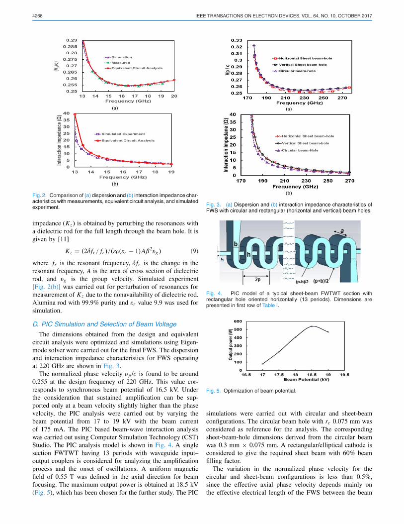
Fig. 2. Comparison of (a) dispersion and (b) interaction impedance char-acteristics with measurements, equivalent circuit analysis, and simulatedexperiment.
impedance (Kz) is obtained by perturbing the resonances witha dielectric rod for the full length through the beam hole. It isgiven by [11]
Kz = (2δ fr/ fr )/(ε0(εr − 1)Aβ2vg) (9)
where fr is the resonant frequency, δ fr is the change in theresonant frequency, A is the area of cross section of dielectricrod, and vg is the group velocity. Simulated experiment[Fig. 2(b)] was carried out for perturbation of resonances formeasurement of Kz due to the nonavailability of dielectric rod.Alumina rod with 99.9% purity and εr value 9.9 was used forsimulation.
D. PIC Simulation and Selection of Beam Voltage
The dimensions obtained from the design and equivalentcircuit analysis were optimized and simulations using Eigen-mode solver were carried out for the final FWS. The dispersionand interaction impedance characteristics for FWS operatingat 220 GHz are shown in Fig. 3.
The normalized phase velocity v p/c is found to be around0.255 at the design frequency of 220 GHz. This value cor-responds to synchronous beam potential of 16.5 kV. Underthe consideration that sustained amplification can be sup-ported only at a beam velocity slightly higher than the phasevelocity, the PIC analysis were carried out by varying thebeam potential from 17 to 19 kV with the beam currentof 175 mA. The PIC based beam-wave interaction analysiswas carried out using Computer Simulation Technology (CST)Studio. The PIC analysis model is shown in Fig. 4. A singlesection FWTWT having 13 periods with waveguide input–output couplers is considered for analyzing the amplificationprocess and the onset of oscillations. A uniform magneticfield of 0.55 T was defined in the axial direction for beamfocusing. The maximum output power is obtained at 18.5 kV(Fig. 5), which has been chosen for the further study. The PIC
Fig. 3. (a) Dispersion and (b) interaction impedance characteristics ofFWS with circular and rectangular (horizontal and vertical) beam holes.
Fig. 4. PIC model of a typical sheet-beam FWTWT section withrectangular hole oriented horizontally (13 periods). Dimensions arepresented in first row of Table I.
Fig. 5. Optimization of beam potential.
simulations were carried out with circular and sheet-beamconfigurations. The circular beam hole with rc 0.075 mm wasconsidered as reference for the analysis. The correspondingsheet-beam-hole dimensions derived from the circular beamwas 0.3 mm × 0.075 mm. A rectangular/elliptical cathode isconsidered to give the required sheet beam with 60% beamfilling factor.
The variation in the normalized phase velocity for thecircular and sheet-beam configurations is less than 0.5%,since the effective axial phase velocity depends mainly onthe effective electrical length of the FWS between the beam

SUDHAMANI et al.: INVESTIGATION OF INSTABILITIES IN FOLDED-WAVEGUIDE SHEET-BEAM TWT 4269
Fig. 6. On-axis field for FWS with circular and rectangular (horizontaland vertical) beam holes.
Fig. 7. Transfer characteristics of FWTWT circular and sheet-beamconfigurations.
crossings and not on the shape of the beam hole [Fig. 3(a)].However, there is 25% enhancement in the on-axis interactionimpedance for the case of rectangular beam hole compared tothat of circular beam hole [Fig. 3(b)].
The on-axis electric field profile for circular and sheet-beam-hole configurations as obtained from the Eigen-modesolver is shown in Fig. 6. The on-axis electric field strengthis highest when there is no beam hole. Even though the beamhole is designed to be in cut-off region, there is leakage ofthe electric field through the beam hole resulting in reductionof on-axis field available for interaction. The leakage electricfield through the rectangular beam hole is found to be smallercompared to that of the circular beam hole resulting in higheron-axis field. Thus, a higher interaction impedance for theFWS configurations having rectangular beam hole is obtained.The transfer characteristics (Fig. 7) also show 1.6 timesenhancement in the output power in the sheet-beam FWTWTcompared to that for a circular-beam FWTWT. However,the vertical sheet-beam FWTWT is prone to oscillations atzero/low drive conditions as will be discussed in the followingsections. The time domain response (Fig. 8) of the zero-driveinput shows the growth of oscillations in the output signal.
III. ZERO-DRIVE OSCILLATIONS
The instability due to zero-drive oscillations in FWTWTwith vertical sheet beam was investigated using PIC solverof CST Studio. The onset of instability in this device wasinvestigated for varying beam potential, beam current, andsheet-beam-hole dimensions.
Fast Fourier transform (FFT) of the output signal in Table IIshows the presence of oscillations for all beam potentials
Fig. 8. PIC output signal amplitude with time for zero-drive input in FWSwith vertical sheet beam (0.3 mm × 0.075 mm) configuration.
TABLE IIZERO-DRIVE OSCILLATIONS VERTICAL BEAM-HOLE
DIMENSIONS 0.3 mm × 0.075 mm
TABLE IIIINTER DEPENDENCE OF BEAM CURRENT AND BEAM-HOLE HEIGHT
FOR ONSET OF ZERO-DRIVE OSCILLATIONS
Fig. 9. PIC output signal amplitude with time for zero-drive inputfor vertical sheet beam hole 0.3 mm × 0.1 mm beam hole (decayingoscillations).
for an FWTWT with a vertical sheet-beam hole of designdimensions (0.3 mm × 0.075 mm). Simulations were carriedout to ascertain the interdependence of beam current andbeam-hole height for zero-drive oscillations at the optimizedbeam potential of 18.5 kV and the results are tabulatedin Table III.
Similar studies were carried out for the horizontal sheet-beam FWTWT with the designed beam-hole dimensionof 0.3 mm × 0.075 mm. The device shows stability withrespect to the beam potential spanning from 17 to 21 kV andbeam current from 0.15 to 0.25 A. PIC simulations were thencarried out to determine beam-hole height threshold for theonset of instability. (Table IV).

4270 IEEE TRANSACTIONS ON ELECTRON DEVICES, VOL. 64, NO. 10, OCTOBER 2017
TABLE IVPRESENCE OF ZERO-DRIVE OSCILLATIONS FOR HIGHEST BEAM
CURRENT AND LOWEST BEAM-HOLE HEIGHT
Fig. 10. Brillouin diagram showing the cavity (dashed lines) and slotmodes (solid lines) for FWS with circular and rectangular (horizontaland vertical) beam holes along with beam line (18.5 kV) interception(straight line).
Table IV shows the presence of oscillations when thebeam-hole height is reduced below 0.07 mm. Hence, for thisspecific case, the beam-hole height threshold for oscillationsis 0.06 mm. The minimum beam-hole height at which hori-zontal sheet-beam device functions as stable amplifier withoutinstabilities due to zero-drive oscillations is 0.07 mm whichresults in the aspect ratio 1:4.3. From Tables III and IV, it isobserved that the start current for oscillations in a horizontalsheet-beam device is 1.42 (0.25/0.175) times higher than thatof the vertical sheet-beam device.
A. Interpretation of the Results
From the preceding results, it is found that the operatingbeam current and the beam-hole dimensions play the crucialrole in determining the stability of the device. The Pierce gainparameter C of an amplifier is defined by the relation
C = (Kz I
/4V
)1/3(10)
where Kz is the interaction impedance, I is the beam current,and V is the beam potential. As the beam current increases,C the gain parameter increases causing the onset of oscilla-tions. In order to, get an insight into the dependence of oscil-lations on beam-hole dimensions, Brillouin diagram (Fig. 10.)is constructed for proposed FWSs with circular, horizontal andvertical beam-hole configurations. Eigen-mode solver of CSTStudio was used to obtain the cavity and the slot resonantfrequencies [14] (Table V).
TABLE VCAVITY AND SLOT MODE FREQUENCIES OF FWS WITH DIFFERENT
BEAM-HOLE CONFIGURATIONS
Fig. 11. 2-D plot of electric field for (a) cavity 2π mode and (b) slot 2πmode for FWS.
TABLE VICAVITY, SLOT 2π FREQUENCIES AND SM AS A FUNCTION OF
SHEET-BEAM-HOLE HEIGHT/RADIUS WITH CONSTANT
WIDTH (0.3 mm) FOR FWSS
Table V shows that the cavity 2π mode frequen-cies for the designed FWSs are very close and varyfrom 278.2 to 280.3 GHz, and there is a large variation(277.8 to 263.7 GHz) for slot mode 2π frequencies.
Brillouin diagram shows that there is coalescing/overlappingof the passbands (cavity and the slot passbands) for FWSs.It is observed that for the FWS with vertical sheet-beam-hole configuration, the cavity 2π mode and slot 2π modefrequencies are very close (278.2 and 277.8 GHz). The beamline intercepts this curve at frequencies close to the cavity2π mode frequency. In the case of the FWSs with circularand horizontal sheet-beam holes, the slot 2π frequencies aremuch lower than the cavity 2π frequencies. This results beamline interception of the dispersion curve at frequencies closerto the slot 2π frequencies.
B. Analysis of the Instabilities
The PIC simulation studies and Brillouin diagram for theFWSs necessitates the study of the field patterns of cavity 2πand slot 2π mode frequencies. The Eigen-mode simulationsof FWS show the 2-D plot of electric field in FWS for thecavity and slot modes at 2π frequencies (Fig. 11). There isa strong on-axis electric field in the cavity 2π mode and

SUDHAMANI et al.: INVESTIGATION OF INSTABILITIES IN FOLDED-WAVEGUIDE SHEET-BEAM TWT 4271
zero on-axis field at slot 2π mode. In the case of FWS withvertical sheet-beam configuration, beam line intercepts arenear the cavity 2π frequency, where the interaction impedanceis very high. Thus, oscillations are triggered even when thereis zero drive [19]. In the case of FWSs with circular andhorizontal sheet-beam configurations, the beamline interceptsare close to the slot 2π frequencies and oscillations will notget triggered as there is zero on-axis electric field resulting inzero interaction impedance. The stable operation of the devicedepends on the amount of coalescing of the cavity and the slotpassband. The extent of coalescing (difference between cavitymode 2π and slot mode 2π frequencies) is defined as thestability margin (SM). The SM is the highest in the case ofhorizontal sheet-beam structure and lowest in the case of thevertical sheet-beam structure (Table VI).
Table VI shows the cavity, slot 2π frequencies and SM withrespect to the sheet-beam-hole height/radius for FWSs withsheet beam and circular beam-hole configurations. As beam-hole height/radius is increased, it is observed that the cavity 2πfrequency is increasing and the slot 2π frequency is decreasingfor all the FWS configurations resulting in the increase ofamount of coalescence and thereby increased SM. The SMlevel is highest in the case of horizontal sheet-beam FWSand lowest in case of vertical sheet-beam FWS. This explainsthe growth of oscillations in vertical sheet-beam FWTWTwith beam-hole height 0.075 mm (Fig. 8.) and decaying ofoscillations when beam-hole height was increased to 0.1 mmfor the same beam current of 0.15A (Fig. 9.). The beam-hole height threshold for oscillations in the case of horizontalsheet-beam FWTWT is 0.06 at an operating current of 0.25 A(Table IV) as SM is high compared to that of vertical sheet-beam FWTWT.
IV. CONCLUSION
This paper was undertaken to understand and analyze thecause of zero-drive oscillations in the high-frequency, high-gain, sheet-beam FWSs used in the TWTs. The parametricdesign of the FWS at 220 GHz, with circular and rectangularbeam-hole (sheet beam) is presented. This paper shows that asheet-beam FWTWT has 25% higher interaction impedanceand 1.6 times higher power compared to a circular-beamdevice.
The present PIC simulation study also explains the causeof zero-drive oscillations in FWTWT circuits. The onset ofinstability in sheet-beam circuits depends on beam current,beam-hole dimensions and its orientation. The Brillouin dia-gram was constructed for the circular, rectangular/horizontal,and rectangular/vertical beam hole orientated FWSs. The insta-bility is directly related to the extent of coalescence of the slotpassband and cavity passbands. The SM (difference betweencavity 2π and slot 2π frequencies) is determined. This papershows that the horizontal sheet-beam FWTWT with an SMof 14.6 GHz, has the best immunity to instability, comparedto the that of the circular beam and vertical beam which haveSMs of 5.8 and 0.4 GHz, respectively.
This paper will aid in the design of horizontal sheet-beamFWTWT, which are stable with higher gain. This paper canbe extended to include higher order modes of operation.
ACKNOWLEDGMENT
The authors would like to thank the Director, MicrowaveTube Research, and Development Centre, Bangalore, India,for permitting to publish this work.
REFERENCES
[1] O. V. Makarova et al., “Fabrication of solid copper 220 GHz foldedwaveguide circuits by UV lithography,” in Proc. Int. Vac. Electron. Conf.,May 2010, pp. 183–184.
[2] J. H. Booske et al., “Accurate parametric modeling of folded waveguidecircuits for millimeter-wave traveling wave tubes,” IEEE Trans. ElectronDevices, vol. 52, no. 5, pp. 685–694, May 2005.
[3] R. Zheng, P. Ohlckers, and X. Chen, “Particle-in-cell simulation andoptimization for a 220-GHz folded-waveguide traveling-wave tube,”IEEE Trans. Electron Devices, vol. 58, no. 7, pp. 2164–2171, Jul. 2011.
[4] S. Bhattacharjee et al., “Folded waveguide traveling-wave tube sourcesfor terahertz radiation,” IEEE Trans. Plasma Sci., vol. 32, no. 3,pp. 1002–1014, Jun. 2004.
[5] S.-T. Han, J.-I. Kim, and G. S. Park, “Design of a folded waveguidetraveling-wave tube,” Microw. Opt. Technol. Lett., vol. 38, no. 2,pp. 161–165, Jul. 2003.
[6] G. Dohler, D. Gagne, D. Gallagher, and R. Moats, “Serpentinewaveguide TWT,” in IEDM Tech. Dig., Dec. 1987, pp. 485–488.
[7] H. S. Sudhamani, J. Balakrishnan, S. U. M. Reddy, and L. Kumar,“Analysis of sheet beam folded waveguide slow wave structures for THzTWTs,” in Proc. 16th IEEE Int. Vac. Electron. Conf. (IVEC), Beijing,China, Apr. 2015, p. 45.
[8] H. S. Sudhamani, S. U. M. Reddy, and J. Balakrishnan, “Simulationand equivalent circuit analysis of folded waveguide structures for THzfrequencies,” in Proc. Nat. Conf. Emerg. Trends Vac. Electron. DevicesAppl. (VEDA), Bangalore, India, Dec. 2015, pp. 63–65.
[9] H. S. Sudhamani, S. U. M. Reddy, and J. Balakrishnan, “PIC simulationsof folded waveguide slow wave structures for THz TWTs,” in Proc.4th Int. Conf. Electron. Warfare (EWCI), Bangalore, India, Feb. 2016,pp. 95–97.
[10] J. R. Pierce, Travelling-Wave Tubes. New York, NY, USA: Van Nostrand,1950.
[11] A. W. Horsley and A. Pearson, “Measurement of dispersion and inter-action impedance characteristics of slow-wave structures by resonancemethods,” IEEE Trans. Electron Devices, vol. 13, no. 12, pp. 962–969,Dec. 1966.
[12] B. Levush et al., “Sheet electron beam millimeter-wave amplifiers at theNaval Research Laboratory,” in Proc. IEEE Conf. COMCAS, Oct. 2013,pp. 1–5.
[13] G. Guo et al., “A research of W-band folded waveguide traveling wavetube with elliptical sheet electron beam,” Phys. Plasmas, vol. 19, no. 9,p. 093117, Sep. 2012.
[14] Computer Simulation Technology (CST) GmbH. CST Studio Suite Ver-sion 2012. Accessed on Jan. 2012. [Online]. Available: http://www.cst.de
[15] N. Marcuvitz, Waveguide Handbook. London, U.K.: Peter Peregrinus,1986.
[16] R. G. E. Hutter, Beam and Wave Electronics in Microwave Tubes.New York, NY, USA: Van Nostrand, 1960.
[17] F. Kantrowitz and I. Tammaru, “Three-dimensional simulations offrequency-phase measurements of arbitrary coupled-cavity RF cir-cuits,” IEEE Trans. Electron Devices, vol. 35, no. 11, pp. 2018–2026,Nov. 1988.
[18] D. G. Dow, “Behavior of traveling-wave tubes near circuit cutoff,” IRETrans. Electron Devices, vol. 7, no. 3, pp. 123–131, Jul. 1960.
[19] J. R. Frey and I. Tammaru, “A coupled-cavity TWT operating in theinverted slot mode,” in IEDM Tech. Dig., Dec. 1981, pp. 504–506.
[20] J. F. Gittins, Power Travelling-Wave Tubes. New York, NY, USA:Elsevier, 1965.
Authors’ photographs and biographies not available at the time ofpublication.