investigation of in-plane moment connections of i-beams to ... · abdelrahim k. dessouki, ahmed h....
TRANSCRIPT

HBRC Journal (2015) 11, 43–56
Housing and Building National Research Center
HBRC Journal
http://ees.elsevier.com/hbrcj
Investigation of in-plane moment connections
of I-beams to square concrete-filled steel tube
columns under gravity loads
* Corresponding author.E-mail address: [email protected] (A.H. Yousef).
Peer review under responsibility of Housing and Building National
Research Center.
Production and hosting by Elsevier
1687-4048 ª 2014 Production and hosting by Elsevier B.V. on behalf of Housing and Building National Research Center.
http://dx.doi.org/10.1016/j.hbrcj.2014.02.011
Abdelrahim K. Dessouki, Ahmed H. Yousef *, Mona M. Fawzy
Structural Engineering Department, Faculty of Engineering, Ain Shams University, Egypt
Received 11 November 2013; revised 15 February 2014; accepted 16 February 2014
KEYWORDS
Experimental and analytical
study;
Concrete-filled steel tubes;
Square columns;
Finite element analysis;
Steel I-beams;
Ultimate moment of
connection
Abstract This paper focuses on experimental and analytical behavior of the ultimate moment of
the connections of steel I-beams to square concrete-filled steel tube columns. External stiffeners
around the columns are used at the beam flange levels. Five specimens are tested monotonically.
The test parameters are the column stiffener dimensions and filling the steel tube column with con-
crete. Two types of failure modes are observed; beam flange failure and stiffener failure. The exper-
imental results show that the ultimate moment of the connection is increased by increasing
stiffener’s dimensions and filling the steel tube column with concrete. ANSYS finite element pro-
gram is used to simulate the behavior, taking into account both geometric and material nonlinear-
ities. Analytical results that are in fair agreement with the experimental ones are then used to discuss
the influence of the main geometric parameters on the connection behavior. The parameters are the
stiffener and column dimensions as well as filling the steel tube column with concrete. Different
square column cross sections are chosen to cover the three classes of section classifications accord-
ing to Egyptian code of practice, which are: compact, non compact or slender. The increase in the
ultimate moment of the connections is based upon both column cross sections’ compactness and
stiffener dimensions while the maximum advantages occur with slender columns.ª 2014 Production and hosting by Elsevier B.V. on behalf of Housing and Building National Research
Center.
Introduction
Concrete-filled steel tube (CFT) columns combine the ductility
generally associated with steel structures with the stiffness ofconcrete components. They have many advantages comparedto other composite column types such as: the steel tube pro-vides a convenient formwork for the concrete; it prevents
spalling of concrete and the concrete core delays local buckling

Stiffener
IPE 300
50
1500
600
2000
Column Not FilledWith Concrete
12
600
Fig. 2 Schematic drawing of specimen NS-50-12.
CFST
Stiffener
I- Beam
Elevation
T
b
c
st
cW
tst
Plan
Fig. 1 Steel I-beam welded to square tube column.
Stiffener
IPE 300
50
1500
600
2000
Column FilledWith Concrete
12
600
Fig. 3 Schematic drawing of specimen CS-50-12.
44 A.K. Dessouki et al.
of the steel tube. Also, the steel tube provides continuousconfinement for the concrete-filling which helps the column
to offer favorable ductility. Consequently, CFT columns maybe well suited for buildings constructed in regions at high seis-mic risks. However, their use has been limited due, in part, to
the difficulties in the design and detailing of satisfactory con-nections, and to the lack of construction experience of suchcolumns.
Several researches have been carried out for decades on dif-ferent types of moment connections of steel I-beams to squaretube columns. The most widely used connection type is theexternal stiffeners that surround the tube columns, as shown
in Fig. 1. The use of external stiffeners increases the ultimatemoment of the connection most significantly. The force trans-fer mechanism of such connection is discussed and verified
against experimental program [1]. The static strength of steelI-beam to rectangular hollow column section connections isa thesis that consists of experimental and numerical investiga-
tions [2]. The influence of concrete filling of the columns as wellas the effect of a composite floor on the behavior and strengthof such connection are included. Ultimate moment of suchconnections is improved by the presence of stiffeners around
the column or by filling the column with concrete becausethe deterioration of the connection due to failure in columnwall is prevented by shifting the stress concentration away
from the column wall. Other research works [3–9] have beencarried out to study the behavior of moment connections ofsteel I-beams to steel tube columns.
In this paper, five experimental tests were carried out mono-tonically. The test parameters are the column stiffener dimen-sions and filling the steel tube column with concrete. A finite
element analysis is presented to model the non-linear behaviorof the in-plane moment connections between steel I-beams andsquare steel tube columns with stiffening plates around the col-umns under vertical loads only, no lateral loads are considered.
The analytical results are verified against the experimental. Thefinite element model is used to conduct a parametric study withdifferent dimensions of square columns, stiffeners and filling
the column with concrete.
Test arrangement and procedure
General
An experimental program of five specimens has been con-ducted to investigate the behavior of moment connections be-
tween steel I-beams and CFT columns. Some parameters aretaken constant throughout the tests such as: the square columncross section dimensions are 250 · 10, the cross section of the
beam is IPE 300, the length of the column is 1500 mm, and thetotal beam span between end supports is 2000 mm. Figs. 2–6illustrate schematic drawings of each specimen showing thelocation of stiffener and other dimensions. Each steel tube col-
umn is fillet welded to a lower end plate of 50 mm thickness atthe bottom, while the top end is kept open to allow filling thetube with concrete. Stiffening plates are welded to the tube col-
umn using fillet welds. Beam flanges are welded to stiffeningplates using complete penetration groove welds, and the beamweb is welded to the tube column using fillet welds. For conve-
nience, each specimen has an individual designation involvingtwo letters followed by a series of numbers, as tabulated inTable 1. The first letter represents the presence of concrete in-side the column, ‘‘N’’ for column not filled with concrete, ‘‘C’’
for column filled with concrete. The second letter represents

Stiffener
IPE 300
75
1500
600
2000
Column FilledWith Concrete
12
600
Fig. 4 Schematic drawing of specimen CS-75-12.
Stiffener
IPE 300
50
1500
600
2000
Column FilledWith Concrete
6
600
Fig. 5 Schematic drawing of specimen CS-50-6.
AA
bf
Stiffener
IPE 300
50
1500
600
2000
Column Not FilledWith Concrete
12
600
Section A-A
Fig. 6 Schematic drawing of specimen NI-50-12.
Table 1 Specimens and stiffener dimensions for current
experimental program.
Specimen Stiffener dimensions (mm) Filling the column
with concretebst tst
NS-50-12 50 12 No
CS-50-12 50 12 Yes
CS-75-12 75 12 Yes
CS-50-6 50 6 Yes
NI-50-12 50 12 No
Investigation of in-plane moment connections 45
shape of stiffener, ‘‘S’’ for square shaped column stiffener, ‘‘I’’for inclined side column stiffener. Meanwhile, the numbers fol-
lowing the letters denote stiffener width (bst) followed by stiff-ener thickness (tst) in mm.
Material properties of test specimens
Specimens CS-50-12, CS-75-12 and CS-50-6 are filled with con-crete of compressive strength 35 MPa, which is the average
compressive strength of five concrete cubes that are cast andtested on the same day as the specimens, and had a minimumage of 28 days prior to testing. An expanding grout admixtureproviding volume expansion and increasing fluidity without
segregation is used. Four steel tensile coupons are cut fromeach flat steel sheet before manufacturing and tested under ten-sion. The results of the tests show that the steel yield strength,
Fy, is 390 MPa for columns, Fy, is 410 MPa for all stiffeners ex-cept for thickness 6 mm, where Fy, is 261 MPa. Finally, for thebeams Fy, is 250 MPa, and the modulus of elasticity of steel,
Es, is 200,000 MPa.
Test setup and loading
The specimens are centered in the testing machine to ensurethat the compressive axial load is applied without any eccen-tricity. The top end of the steel tubes is covered first with the
cap plate of thickness 50 mm and then rested on the upperbearing of the testing machine which itself rests on a ball bear-
ing to allow rotation in all directions. Column load, as mea-sured by test machine load cell, is applied at very slow rateand is maintained for about one minute to record the measure-
ments. So, the connection between steel I-beams and squaretube columns will be subjected to in-plane moment and the col-umn is not preloaded. To produce two pin ends of the beams,
the beam end is rested on a roller bearing. This roller bearingconsists of two thick plates 200 · 200 mm with 40 mm thick-ness, and the two plates have a groove of depth 8 mm. A cylin-drical roller of diameter 40 mm is placed above the two plates
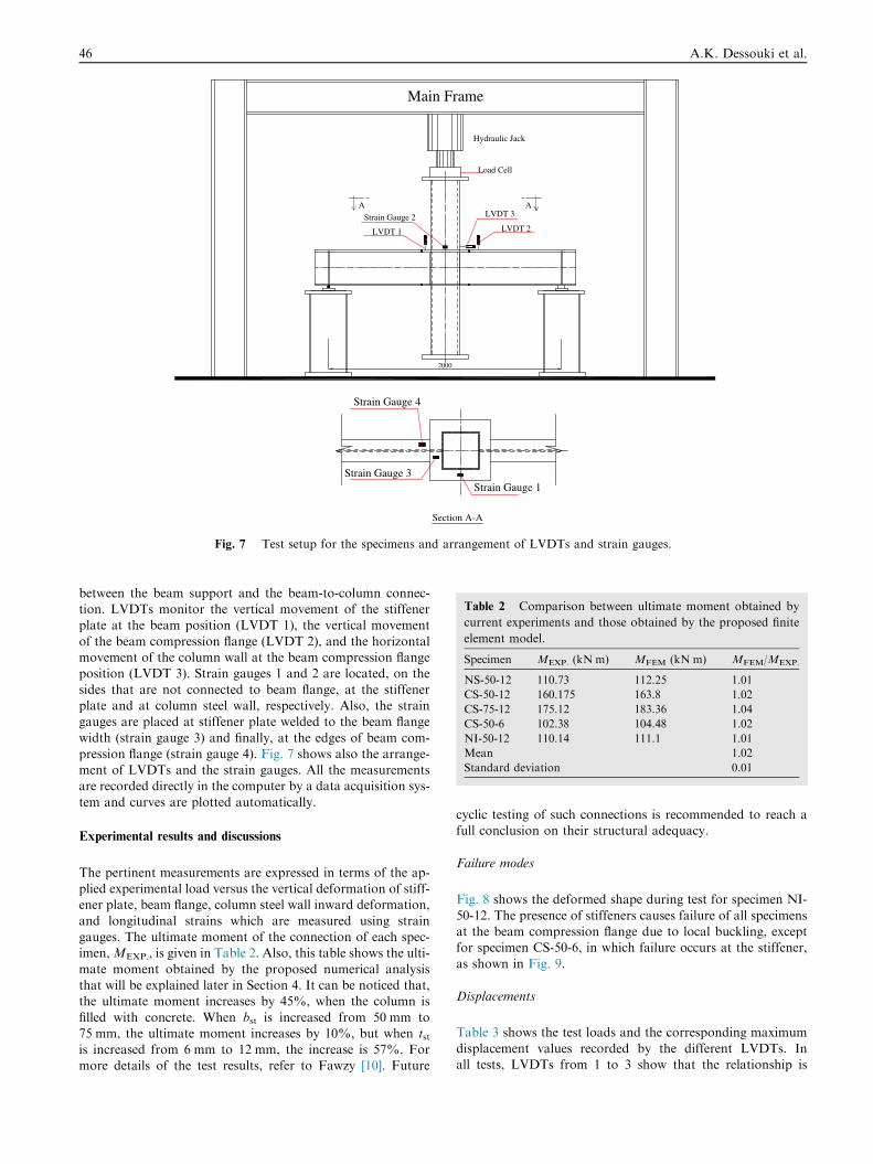
to allow end rotation without sliding. Fig. 7 shows a schematicdrawing for the loading and instrumentation setup.
Instrumentation
The load cell, which is used to record the applied load, isplaced between the top end of the specimen and the testing ma-
chine. The values of ultimate moment of the connections areobtained as the reaction force at the beam support, which ishalf the value measured by load cell, multiplied by the distance
Load Cell
Strain Gauge 2
Hydraulic Jack
Main Frame
LVDT 3
LVDT 1 LVDT 2
2000
AA
Strain Gauge 1Strain Gauge 3
Section A-A
Strain Gauge 4
Fig. 7 Test setup for the specimens and arrangement of LVDTs and strain gauges.
Table 2 Comparison between ultimate moment obtained by
current experiments and those obtained by the proposed finite
element model.
Specimen MEXP. (kN m) MFEM (kN m) MFEM/MEXP.
NS-50-12 110.73 112.25 1.01
CS-50-12 160.175 163.8 1.02
CS-75-12 175.12 183.36 1.04
CS-50-6 102.38 104.48 1.02
NI-50-12 110.14 111.1 1.01
Mean 1.02
Standard deviation 0.01
46 A.K. Dessouki et al.
between the beam support and the beam-to-column connec-tion. LVDTs monitor the vertical movement of the stiffenerplate at the beam position (LVDT 1), the vertical movement
of the beam compression flange (LVDT 2), and the horizontalmovement of the column wall at the beam compression flangeposition (LVDT 3). Strain gauges 1 and 2 are located, on the
sides that are not connected to beam flange, at the stiffenerplate and at column steel wall, respectively. Also, the straingauges are placed at stiffener plate welded to the beam flange
width (strain gauge 3) and finally, at the edges of beam com-pression flange (strain gauge 4). Fig. 7 shows also the arrange-ment of LVDTs and the strain gauges. All the measurementsare recorded directly in the computer by a data acquisition sys-
tem and curves are plotted automatically.
Experimental results and discussions
The pertinent measurements are expressed in terms of the ap-plied experimental load versus the vertical deformation of stiff-ener plate, beam flange, column steel wall inward deformation,
and longitudinal strains which are measured using straingauges. The ultimate moment of the connection of each spec-imen,MEXP., is given in Table 2. Also, this table shows the ulti-
mate moment obtained by the proposed numerical analysisthat will be explained later in Section 4. It can be noticed that,the ultimate moment increases by 45%, when the column is
filled with concrete. When bst is increased from 50 mm to75 mm, the ultimate moment increases by 10%, but when tstis increased from 6 mm to 12 mm, the increase is 57%. Formore details of the test results, refer to Fawzy [10]. Future
cyclic testing of such connections is recommended to reach afull conclusion on their structural adequacy.
Failure modes
Fig. 8 shows the deformed shape during test for specimen NI-
50-12. The presence of stiffeners causes failure of all specimensat the beam compression flange due to local buckling, exceptfor specimen CS-50-6, in which failure occurs at the stiffener,
as shown in Fig. 9.
Displacements
Table 3 shows the test loads and the corresponding maximum
displacement values recorded by the different LVDTs. Inall tests, LVDTs from 1 to 3 show that the relationship is

Fig. 8 Deformed shape during test for specimen NI-50-12.
Fig. 9 Stiffener failure for specimen CS-50-6.
Table 3 Test loads and the corresponding maximum values
recorded by LVDTs (mm).
Specimen Loads (kN) LVDT 1 LVDT 2 LVDT 3
NS-50-12 268.3 13.5 19.3 3
CS-50-12 359 1.23 14.7 2
CS-75-12 437 6.5 12.8 1.5
CS-50-6 248.2 7.3 13.1 1.84
NI-50-12 267 11.9 13.7 6
Fig. 10 Horizontal displacement of column steel wall measured
by LVDT 3 versus applied load for specimen NS-50-12.
Fig. 11 Vertical displacement of beam flange measured by
LVDT 2 versus applied load for specimen NI-50-12.
Investigation of in-plane moment connections 47
nonlinear, characterized by an ascending branch up to failureand the maximum displacement at failure is considerably in-creased. For specimen CS-50-12, where column is filled with
concrete, local buckling of the stiffener and of the beam com-pression flanges is decreased by 90% and 25%, respectively,compared to specimen NS-50-12. By decreasing the thickness
of the stiffener to 6 mm, its vertical displacement increasesby 53% and the local buckling of the beam compression flangedecreases by 20%. In specimen NI-50-12, the stiffener shape
has no sharp edges, thus the local buckling decreases by14% and 30% for stiffener and beam compression flange,
respectively, with respect to specimen NS-50-12. The face ofthe column steel wall of specimens NS-50-12 and NI-50-12 de-
forms inward at the compression flange location by 3 mm and6 mm, respectively. The deformations decrease when the spec-imens are filled with concrete, causing displacement of 2 mm
for specimen CS-50-12 and 1.5 mm for specimen CS-75-12.So, the ductility of the connection increases by not filling thetube with concrete and by reducing stiffener thickness, but
the ultimate moment is reduced. Fig. 10 shows horizontal dis-placement of column steel wall measured by LVDT 3 for spec-imen NS-50-12. It can be noticed that the displacementdecreases under load in the lower part before it increases, since
column wall may not yet started obtaining the load from thebeam. Also, Figs. 11–13 show vertical displacement of beamflange measured by LVDT 2 for specimens NI-50-12, CS-50-
6 and CS-50-12, respectively.
Strains
Table 4 shows the test loads and the corresponding maximumstrain values recorded by the different strain gauges. The com-mon feature in strain curves is that the relationship is directly
proportional to failure. Filling the column with concrete de-creases the strains recorded by strain gauges 1 and 2 by 95%and 88%, respectively, as the concrete decreases the local

Fig. 13 Vertical displacement of beam flange measured by
LVDT 2 versus applied load for specimen CS-50-12.
Fig. 12 Vertical displacement of beam flange measured by
LVDT 2 versus applied load for specimen CS-50-6.
Fig. 14 Average micro strain of stiffener by strain gauge 1 versus
applied load for specimen CS-50-6.
Fig. 15 Average micro strain of beam flange by strain gauge 4
versus applied load of specimen CS-50-6.
48 A.K. Dessouki et al.
buckling of the adjacent elements. However, Strain gauge 3
shows an increase in the strains by three times, which signifiesthe role of concrete that shifts the local buckling waves towardthe stiffener zone and accordingly, strain gauge 4 detects a de-
crease in the strains by 48%.Local buckling of the stiffener is inevitable as bst increases
and tst decreases. The increase in the strains measured by straingauge 1 is almost 3.6 times for specimen CS-75-12 compared to
CS-50-12 and is 4.5 times for specimen CS-50-6 compared toCS-50-12. Similarly, the strains, recorded by strain gauge 2, in-crease by 38% for specimen CS-75-12 compared to CS-50-12,
but almost are not affected by changing tst. Also, by increasing
Table 4 Test loads and the corresponding maximum strain values
Specimen Loads (kN) Strain gauge 1
NS-50-12 268.3 422
CS-50-12 359 22.5
CS-75-12 437 82
CS-50-6 248.2 100
NI-50-12 267 65.5
bst, the strains decrease by 66% as a result of redistribution atthe location of strain gauge 3. The strains recorded by strain
gauge 4 at beam compression flange are doubled in specimenCS-75-12 compared to CS-50-12, meanwhile, it increases by11% in specimen CS-50-6 compared to specimen CS-50-12.
Figs. 14 and 15 show average micro strain for specimen CS-50-6 of stiffener by strain gauge 1 and of beam flange by straingauge 4, respectively.
The least value of the strains is recorded by strain gauge 1that is located at specimen NI-50-12, compared to NS-50-12,as a sign of the small portion of the stresses passing aroundthe column wall. Also, a decrease in the strains by 35%, at
the location of strain gauge 2 is noticed. However, there isan increase in the strains recorded by strain gauge 3 by 5%,accompanied by a decrease of 24% in the strains that are re-
corded by strain gauge 4. Although the shape of the stiffenerinfluences the stress path through the connection, the ultimatemoment of the connection is slightly affected between speci-
mens NS-50-12 and NI-50-12.
recorded by strain gauges (micro strain).
Strain gauge 2 Strain gauge 3 Strain gauge 4
739 2930 12,270
95 9550 6380
131 3230 15,130
91 15,020 7030
482.6 3090 9320
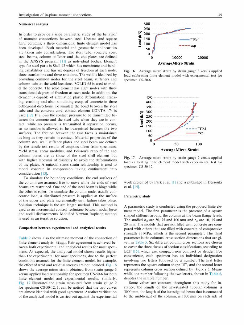
Fig. 16 Average micro strain by strain gauge 3 versus applied
load calibrating finite element model with experimental test for
specimen CS-50-6.
Fig. 17 Average micro strain by strain gauge 2 versus applied
load calibrating finite element model with experimental test for
specimen CS-50-12.
Investigation of in-plane moment connections 49
Numerical analysis
In order to provide a wide parametric study of the behaviorof moment connections between steel I-beams and square
CFT columns, a three dimensional finite element model hasbeen developed. Both material and geometric nonlinearitiesare taken into consideration. The steel tube, concrete core,
steel beams, column stiffener and the end plates are definedin the ANSYS program [11] as individual bodies. Elementtype for steel parts is Shell 43 which has membrane and bend-ing capabilities and has six degrees of freedom at each node;
three translations and three rotations. The weld is idealized byproviding common nodes for the steel beam, stiffeners andcolumn tube at the weld locations. SOLID 65 is used to mod-
el the concrete. The solid element has eight nodes with threetransitional degrees of freedom at each node. In addition, theelement is capable of simulating plastic deformation, crack-
ing, crushing and also, simulating creep of concrete in threeorthogonal directions. To simulate the bond between the steeltube and the concrete core, contact element CONTA 174 is
used [12]. It allows the contact pressure to be transmitted be-tween the concrete and the steel tube when they are in con-tact, while no pressure is transmitted if separation occurs,so no tension is allowed to be transmitted between the two
surfaces. The friction between the two faces is maintainedas long as they remain in contact. Material properties of thecolumn steel wall, stiffener plates and steel beam are defined
by the tensile test results of coupons taken from specimens.Yield stress, shear modulus, and Poisson’s ratio of the endcolumn plates are as those of the steel shell element but
with higher modulus of elasticity to avoid the deformationsof the plates. A uniaxial stress strain relationship is used tomodel concrete in compression taking confinement into
consideration [13].To simulate the boundary conditions, the end surfaces of
the column are assumed free to move while the ends of steelbeams are restrained. One end of the steel beam is hinge while
the other is roller. To simulate the column under axially con-centric load, a distributed pressure is applied at the surfaceof the upper end plate incrementally until failure takes place.
Solution technique is the arc length method. This method isused as an incremental control technique between nodal forceand nodal displacements. Modified Newton Raphson method
is used as an iterative solution.
Comparison between experimental and analytical results
Table 2 shows also the ultimate moment of the connection offinite element analysis, MFEM. Fair agreement is achieved be-tween both experimental and analytical results for most speci-mens. As expected, the analytical model shows results higher
than the experimental for most specimens, due to the perfectconditions assumed for the finite element model, for example,the effect of weld and residual stresses are not included. Fig. 16
shows the average micro strain obtained from strain gauge 3versus applied load relationship for specimen CS-50-6 for bothfinite element model and experimental results. Similarly,
Fig. 17 illustrates the strain measured from strain gauge 2for specimen CS-50-12. It can be noticed that the two curvesare almost identical with good agreement. Another verification
of the analytical model is carried out against the experimental
work presented by Park et al. [1] and is published in Dessouki
et al. [14].
Parametric study
A parametric study is conducted using the proposed finite ele-ment model. The first parameter is the presence of a squareshaped stiffener around the column at the beam flange levels.
The studied bst are 50, 75 and 100 mm and tst are 10, 15 and20 mm. The models that are not filled with concrete are com-pared with others that are filled with concrete of compressivestrength 35 MPa, which is the second parameter. The third
parameter is the columns’ cross section dimensions that are gi-ven in Table 5. Six different column cross sections are chosento cover the three classes of section classifications according to
ECP [15], which are: compact, non compact or slender. Forconvenience, each specimen has an individual designationinvolving two letters followed by a number. The first letter
represents the square column shape ‘‘S’’, and the second letterrepresents column cross section defined by (Wc · Tc). Mean-while, the number following the two letters, shown in Table 6,denotes the sample number.
Some values are constant throughout this study for in-stance, the length of the investigated tubular columns is3000 mm, the length of the investigated beam that is connected
to the mid-height of the column, is 1000 mm on each side of
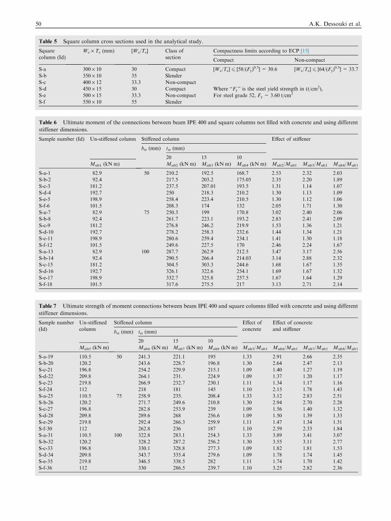
Table 6 Ultimate moment of the connections between beam IPE 400 and square columns not filled with concrete and using different
stiffener dimensions.
Sample number (Id) Un-stiffened column Stiffened column Effect of stiffener
bst (mm) tst (mm)
20 15 10
Mult1 (kN m) Mult2 (kN m) Mult3 (kN m) Mult4 (kN m) Mult2/Mult1 Mult3/Mult1 Mult4/Mult1
S-a-1 82.9 50 210.2 192.5 168.7 2.53 2.32 2.03
S-b-2 92.4 217.5 203.2 175.05 2.35 2.20 1.89
S-c-3 181.2 237.5 207.01 193.5 1.31 1.14 1.07
S-d-4 192.7 250 218.3 210.2 1.30 1.13 1.09
S-e-5 198.9 258.4 223.4 210.5 1.30 1.12 1.06
S-f-6 101.5 208.3 174 132 2.05 1.71 1.30
S-a-7 82.9 75 250.3 199 170.8 3.02 2.40 2.06
S-b-8 92.4 261.7 223.1 193.2 2.83 2.41 2.09
S-c-9 181.2 276.8 246.2 219.9 1.53 1.36 1.21
S-d-10 192.7 278.2 258.3 232.6 1.44 1.34 1.21
S-e-11 198.9 280.6 259.4 234.1 1.41 1.30 1.18
S-f-12 101.5 249.6 227.5 170 2.46 2.24 1.67
S-a-13 82.9 100 287.7 262.9 212.5 3.47 3.17 2.56
S-b-14 92.4 290.5 266.4 214.03 3.14 2.88 2.32
S-c-15 181.2 304.5 303.3 244.6 1.68 1.67 1.35
S-d-16 192.7 326.1 322.6 254.1 1.69 1.67 1.32
S-e-17 198.9 332.7 325.8 257.5 1.67 1.64 1.29
S-f-18 101.5 317.6 275.5 217 3.13 2.71 2.14
Table 7 Ultimate strength of moment connections between beam IPE 400 and square columns filled with concrete and using different
stiffener dimensions.
Sample number
(Id)
Un-stiffened
column
Stiffened column Effect of
concrete
Effect of concrete
and stiffenerbst (mm) tst (mm)
20 15 10
Mult5 (kN m) Mult6 (kN m) Mult7 (kN m) Mult8 (kN m) Mult5/Mult1 Mult6/Mult1 Mult7/Mult1 Mult8/Mult1
S-a-19 110.5 50 241.3 221.1 195 1.33 2.91 2.66 2.35
S-b-20 120.2 243.6 228.7 196.8 1.30 2.64 2.47 2.13
S-c-21 196.8 254.2 229.9 215.1 1.09 1.40 1.27 1.19
S-d-22 209.8 264.1 231. 224.9 1.09 1.37 1.20 1.17
S-e-23 219.8 266.9 232.7 230.1 1.11 1.34 1.17 1.16
S-f-24 112 218 181 145 1.10 2.15 1.78 1.43
S-a-25 110.5 75 258.9 235. 208.4 1.33 3.12 2.83 2.51
S-b-26 120.2 271.7 249.6 210.8 1.30 2.94 2.70 2.28
S-c-27 196.8 282.8 253.9 239 1.09 1.56 1.40 1.32
S-d-28 209.8 289.6 268 256.6 1.09 1.50 1.39 1.33
S-e-29 219.8 292.4 266.3 259.9 1.11 1.47 1.34 1.31
S-f-30 112 262.8 236 187 1.10 2.59 2.33 1.84
S-a-31 110.5 100 322.8 283.1 254.3 1.33 3.89 3.41 3.07
S-b-32 120.2 328.2 287.2 256.2 1.30 3.55 3.11 2.77
S-c-33 196.8 330.1 328.8 277.3 1.09 1.82 1.81 1.53
S-d-34 209.8 343.7 335.4 279.6 1.09 1.78 1.74 1.45
S-e-35 219.8 346.5 338.5 282 1.11 1.74 1.70 1.42
S-f-36 112 330 286.5 239.7 1.10 3.25 2.82 2.36
Table 5 Square column cross sections used in the analytical study.
Square
column (Id)
Wc · Tc (mm) [Wc/Tc] Class of
section
Compactness limits according to ECP [15]
Compact Non-compact
S-a 300 · 10 30 Compact [Wc/Tc] 6 [58/(Fy)0.5] = 30.6 [Wc/Tc] 6 [64/(Fy)
0.5] = 33.7
S-b 350 · 10 35 Slender
S-c 400 · 12 33.3 Non-compact
S-d 450 · 15 30 Compact Where ‘‘Fy’’ is the steel yield strength in (t/cm2),
For steel grade 52, Fy = 3.60 t/cm2S-e 500 · 15 33.3 Non-compact
S-f 550 · 10 55 Slender
50 A.K. Dessouki et al.

Fig. 18 Stress distribution (t/cm2) of un-stiffened square column
300 · 10 not filled with concrete.
Fig. 19 Stress distribution (t/cm2) of square column 300 · 10
with stiffener 50 · 20 not filled with concrete.
Fig. 20 Mult/Mp ratio versus tst for column S-a with different bst.
Fig. 21 Mult/Mp ratio versus tst for column S-b with different bst.
Fig. 22 Mult/Mp ratio versus tst for column S-c with different bst.
Fig. 23 Mult/Mp ratio versus tst for column S-d with different bst.
Investigation of in-plane moment connections 51
the column wall and finally, the beam cross section is IPE 400.The curves are plotted showing a non dimensional ratiobetween ultimate moment of the connection to the plasticmoment of the beam (Mult/Mp) versus bst or tst.
Results and discussions of numerical analysis
Table 6 shows the effect of changing stiffener and square col-
umn cross section dimensions on the ultimate moment of theconnections; while Table 7 demonstrates the effect of fillingthe column with concrete only or using both stiffeners and fill-ing the column with concrete.
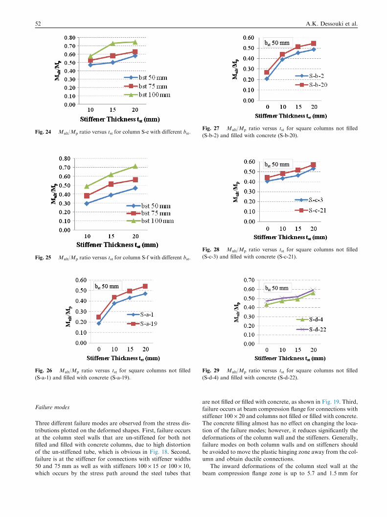
Fig. 24 Mult/Mp ratio versus tst for column S-e with different bst.
Fig. 26 Mult/Mp ratio versus tst for square columns not filled
(S-a-1) and filled with concrete (S-a-19).
Fig. 25 Mult/Mp ratio versus tst for column S-f with different bst.
Fig. 27 Mult/Mp ratio versus tst for square columns not filled
(S-b-2) and filled with concrete (S-b-20).
Fig. 28 Mult/Mp ratio versus tst for square columns not filled
(S-c-3) and filled with concrete (S-c-21).
Fig. 29 Mult/Mp ratio versus tst for square columns not filled
(S-d-4) and filled with concrete (S-d-22).
52 A.K. Dessouki et al.
Failure modes
Three different failure modes are observed from the stress dis-
tributions plotted on the deformed shapes. First, failure occursat the column steel walls that are un-stiffened for both notfilled and filled with concrete columns, due to high distortion
of the un-stiffened tube, which is obvious in Fig. 18. Second,failure is at the stiffener for connections with stiffener widths50 and 75 mm as well as with stiffeners 100 · 15 or 100 · 10,which occurs by the stress path around the steel tubes that
are not filled or filled with concrete, as shown in Fig. 19. Third,
failure occurs at beam compression flange for connections withstiffener 100 · 20 and columns not filled or filled with concrete.The concrete filling almost has no effect on changing the loca-
tion of the failure modes; however, it reduces significantly thedeformations of the column wall and the stiffeners. Generally,failure modes on both column walls and on stiffeners should
be avoided to move the plastic hinging zone away from the col-umn and obtain ductile connections.
The inward deformations of the column steel wall at thebeam compression flange zone is up to 5.7 and 1.5 mm for
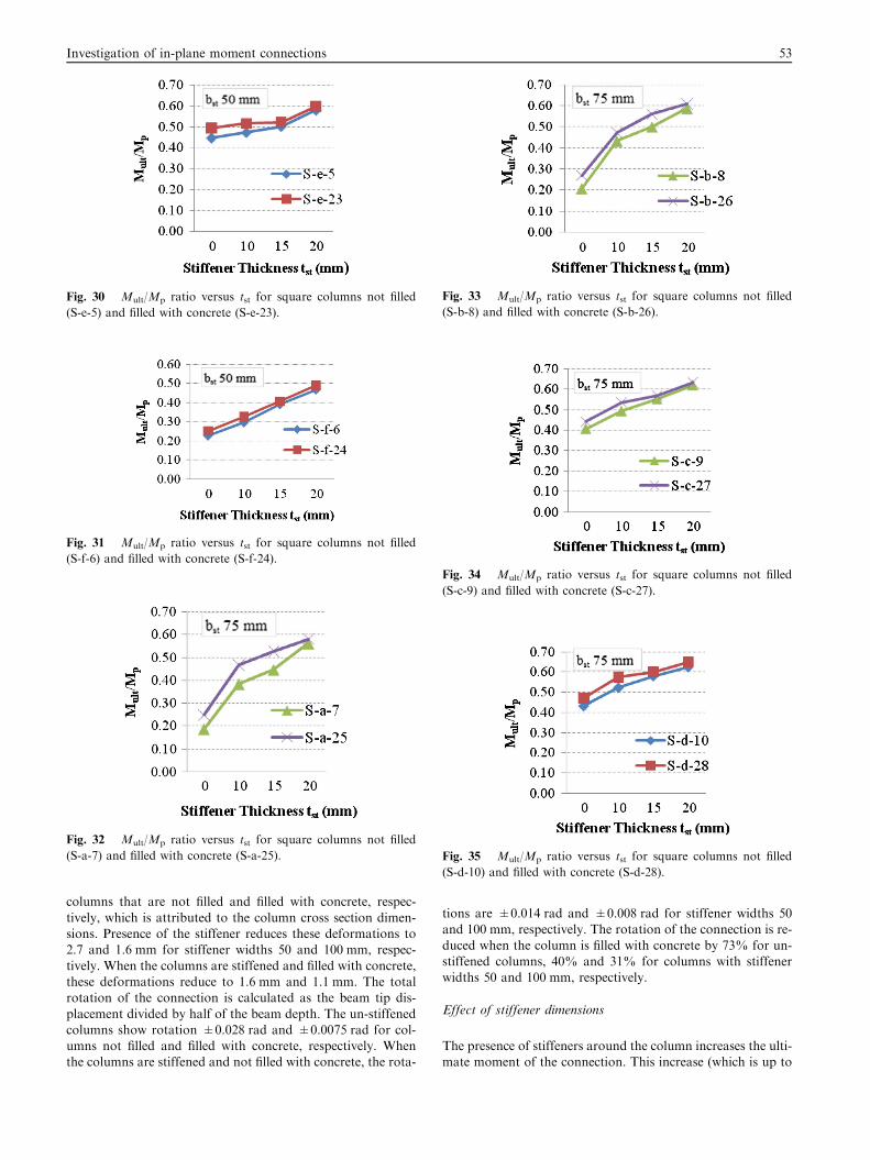
Fig. 31 Mult/Mp ratio versus tst for square columns not filled
(S-f-6) and filled with concrete (S-f-24).
Fig. 32 Mult/Mp ratio versus tst for square columns not filled
(S-a-7) and filled with concrete (S-a-25).
Fig. 30 Mult/Mp ratio versus tst for square columns not filled
(S-e-5) and filled with concrete (S-e-23).
Fig. 33 Mult/Mp ratio versus tst for square columns not filled
(S-b-8) and filled with concrete (S-b-26).
Fig. 34 Mult/Mp ratio versus tst for square columns not filled
(S-c-9) and filled with concrete (S-c-27).
Fig. 35 Mult/Mp ratio versus tst for square columns not filled
(S-d-10) and filled with concrete (S-d-28).
Investigation of in-plane moment connections 53
columns that are not filled and filled with concrete, respec-
tively, which is attributed to the column cross section dimen-sions. Presence of the stiffener reduces these deformations to2.7 and 1.6 mm for stiffener widths 50 and 100 mm, respec-
tively. When the columns are stiffened and filled with concrete,these deformations reduce to 1.6 mm and 1.1 mm. The totalrotation of the connection is calculated as the beam tip dis-
placement divided by half of the beam depth. The un-stiffenedcolumns show rotation ±0.028 rad and ±0.0075 rad for col-umns not filled and filled with concrete, respectively. Whenthe columns are stiffened and not filled with concrete, the rota-
tions are ±0.014 rad and ±0.008 rad for stiffener widths 50and 100 mm, respectively. The rotation of the connection is re-
duced when the column is filled with concrete by 73% for un-stiffened columns, 40% and 31% for columns with stiffenerwidths 50 and 100 mm, respectively.
Effect of stiffener dimensions
The presence of stiffeners around the column increases the ulti-mate moment of the connection. This increase (which is up to
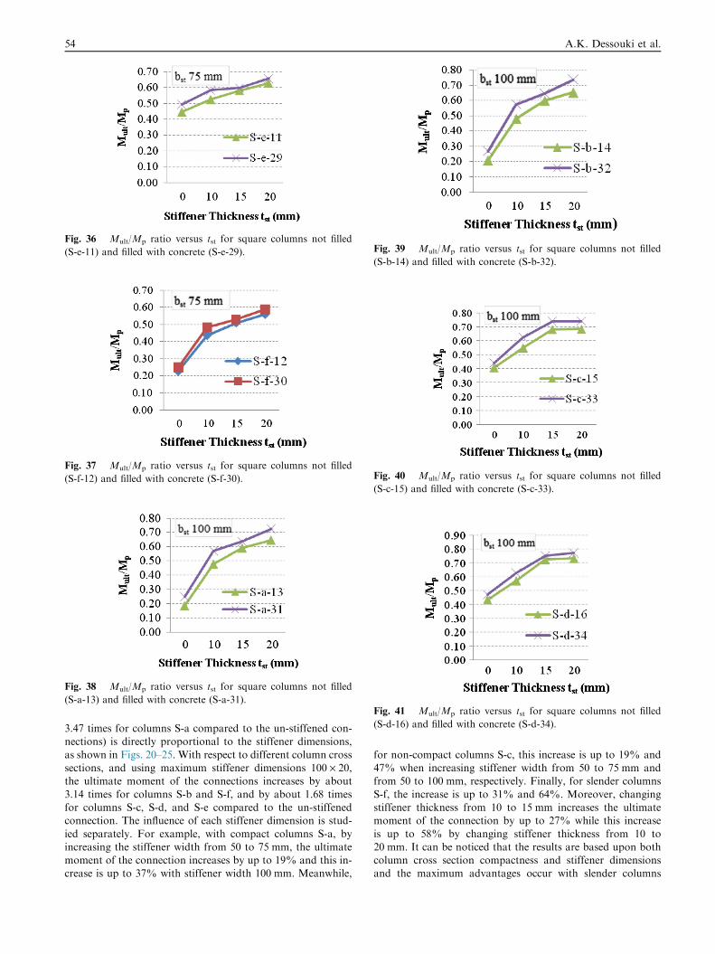
Fig. 36 Mult/Mp ratio versus tst for square columns not filled
(S-e-11) and filled with concrete (S-e-29).
Fig. 37 Mult/Mp ratio versus tst for square columns not filled
(S-f-12) and filled with concrete (S-f-30).
Fig. 38 Mult/Mp ratio versus tst for square columns not filled
(S-a-13) and filled with concrete (S-a-31).
Fig. 39 Mult/Mp ratio versus tst for square columns not filled
(S-b-14) and filled with concrete (S-b-32).
Fig. 40 Mult/Mp ratio versus tst for square columns not filled
(S-c-15) and filled with concrete (S-c-33).
Fig. 41 Mult/Mp ratio versus tst for square columns not filled
(S-d-16) and filled with concrete (S-d-34).
54 A.K. Dessouki et al.
3.47 times for columns S-a compared to the un-stiffened con-nections) is directly proportional to the stiffener dimensions,
as shown in Figs. 20–25. With respect to different column crosssections, and using maximum stiffener dimensions 100 · 20,the ultimate moment of the connections increases by about
3.14 times for columns S-b and S-f, and by about 1.68 timesfor columns S-c, S-d, and S-e compared to the un-stiffenedconnection. The influence of each stiffener dimension is stud-
ied separately. For example, with compact columns S-a, byincreasing the stiffener width from 50 to 75 mm, the ultimatemoment of the connection increases by up to 19% and this in-crease is up to 37% with stiffener width 100 mm. Meanwhile,
for non-compact columns S-c, this increase is up to 19% and47% when increasing stiffener width from 50 to 75 mm andfrom 50 to 100 mm, respectively. Finally, for slender columns
S-f, the increase is up to 31% and 64%. Moreover, changingstiffener thickness from 10 to 15 mm increases the ultimatemoment of the connection by up to 27% while this increase
is up to 58% by changing stiffener thickness from 10 to20 mm. It can be noticed that the results are based upon bothcolumn cross section compactness and stiffener dimensionsand the maximum advantages occur with slender columns
Investigation of in-plane moment connections 55
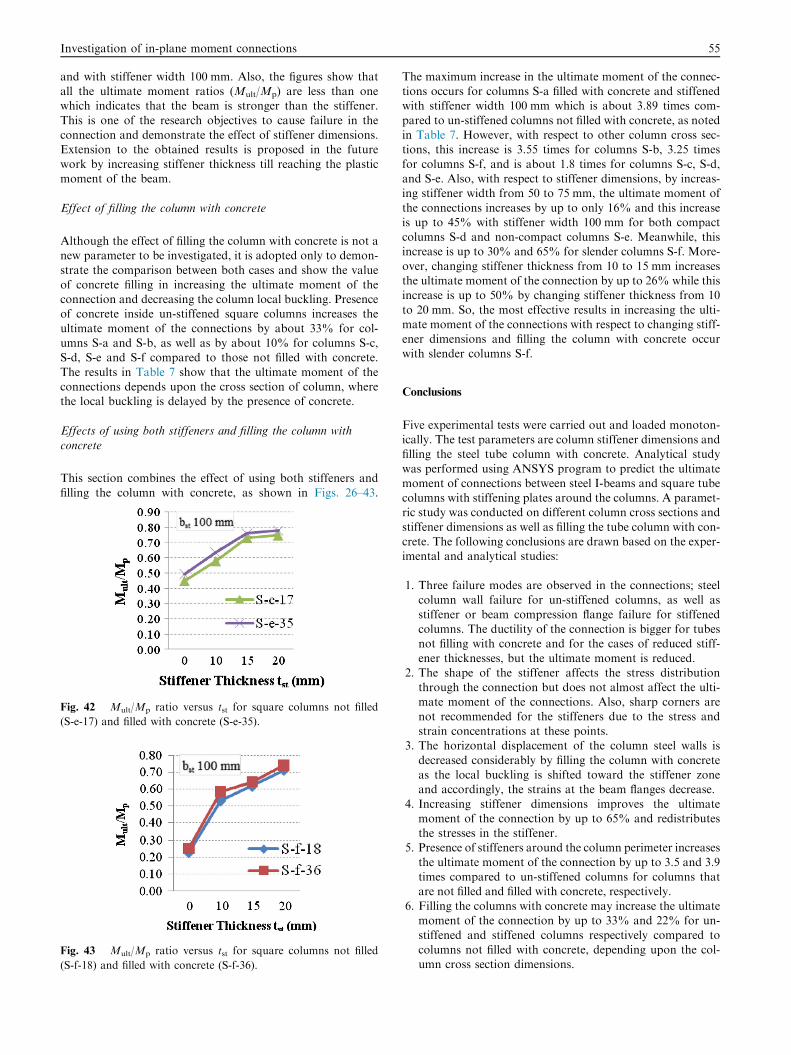
and with stiffener width 100 mm. Also, the figures show thatall the ultimate moment ratios (Mult/Mp) are less than onewhich indicates that the beam is stronger than the stiffener.
This is one of the research objectives to cause failure in theconnection and demonstrate the effect of stiffener dimensions.Extension to the obtained results is proposed in the future
work by increasing stiffener thickness till reaching the plasticmoment of the beam.
Effect of filling the column with concrete
Although the effect of filling the column with concrete is not anew parameter to be investigated, it is adopted only to demon-
strate the comparison between both cases and show the valueof concrete filling in increasing the ultimate moment of theconnection and decreasing the column local buckling. Presenceof concrete inside un-stiffened square columns increases the
ultimate moment of the connections by about 33% for col-umns S-a and S-b, as well as by about 10% for columns S-c,S-d, S-e and S-f compared to those not filled with concrete.
The results in Table 7 show that the ultimate moment of theconnections depends upon the cross section of column, wherethe local buckling is delayed by the presence of concrete.
Effects of using both stiffeners and filling the column with
concrete
This section combines the effect of using both stiffeners and
filling the column with concrete, as shown in Figs. 26–43.
Fig. 42 Mult/Mp ratio versus tst for square columns not filled
(S-e-17) and filled with concrete (S-e-35).
Fig. 43 Mult/Mp ratio versus tst for square columns not filled
(S-f-18) and filled with concrete (S-f-36).
The maximum increase in the ultimate moment of the connec-tions occurs for columns S-a filled with concrete and stiffenedwith stiffener width 100 mm which is about 3.89 times com-
pared to un-stiffened columns not filled with concrete, as notedin Table 7. However, with respect to other column cross sec-tions, this increase is 3.55 times for columns S-b, 3.25 times
for columns S-f, and is about 1.8 times for columns S-c, S-d,and S-e. Also, with respect to stiffener dimensions, by increas-ing stiffener width from 50 to 75 mm, the ultimate moment of
the connections increases by up to only 16% and this increaseis up to 45% with stiffener width 100 mm for both compactcolumns S-d and non-compact columns S-e. Meanwhile, thisincrease is up to 30% and 65% for slender columns S-f. More-
over, changing stiffener thickness from 10 to 15 mm increasesthe ultimate moment of the connection by up to 26% while thisincrease is up to 50% by changing stiffener thickness from 10
to 20 mm. So, the most effective results in increasing the ulti-mate moment of the connections with respect to changing stiff-ener dimensions and filling the column with concrete occur
with slender columns S-f.
Conclusions
Five experimental tests were carried out and loaded monoton-ically. The test parameters are column stiffener dimensions andfilling the steel tube column with concrete. Analytical study
was performed using ANSYS program to predict the ultimatemoment of connections between steel I-beams and square tubecolumns with stiffening plates around the columns. A paramet-ric study was conducted on different column cross sections and
stiffener dimensions as well as filling the tube column with con-crete. The following conclusions are drawn based on the exper-imental and analytical studies:
1. Three failure modes are observed in the connections; steelcolumn wall failure for un-stiffened columns, as well as
stiffener or beam compression flange failure for stiffenedcolumns. The ductility of the connection is bigger for tubesnot filling with concrete and for the cases of reduced stiff-
ener thicknesses, but the ultimate moment is reduced.2. The shape of the stiffener affects the stress distribution
through the connection but does not almost affect the ulti-mate moment of the connections. Also, sharp corners are
not recommended for the stiffeners due to the stress andstrain concentrations at these points.
3. The horizontal displacement of the column steel walls is
decreased considerably by filling the column with concreteas the local buckling is shifted toward the stiffener zoneand accordingly, the strains at the beam flanges decrease.
4. Increasing stiffener dimensions improves the ultimatemoment of the connection by up to 65% and redistributesthe stresses in the stiffener.
5. Presence of stiffeners around the column perimeter increases
the ultimate moment of the connection by up to 3.5 and 3.9times compared to un-stiffened columns for columns thatare not filled and filled with concrete, respectively.
6. Filling the columns with concrete may increase the ultimatemoment of the connection by up to 33% and 22% for un-stiffened and stiffened columns respectively compared to
columns not filled with concrete, depending upon the col-umn cross section dimensions.
56 A.K. Dessouki et al.
7. Filling the columns with concrete decreases the rotation of
the connection by 73% for un-stiffened columns, 40% and31% for columns stiffened with stiffener widths 50 and100 mm, respectively.
8. The increase in the ultimate moment of the connections isbased upon both column cross sections’ compactness andstiffener dimensions and the maximum advantages occurwith slender columns.
Conflict of interest
None.
Acknowledgements
The experimental work presented in this research was carriedout at the Structural Engineering Laboratory, Faculty of
Engineering, Tanta University, Egypt. Specifically, the authorswould like to thank and appreciate the help provided by Prof.Dr. Mohamed Ahmed Dabaon, Professor of Steel Structures
and Bridges and Vice President of Tanta University.
References
[1] J.W. Park, S.M. Kang, S.C. Yang, Experimental studies of wide
flange beam to square concrete-filled tube column joints with
stiffening plates around the column, J. Struct. Eng. ASCE 12
(2005) 131–140.
[2] L.H. Lu, The static strength of I-beam to rectangular hollow
section column connections (Ph.D. thesis), Faculty of Civil
Engineering and Geosciences, Delft University of Technology,
1997.
[3] S.R. Mirghaderi, S. Torabian, F. Keshavarzi, I-beam to box–
column connection by a vertical plate passing through the
column, Eng. Struct. 32 (8) (2010) 2034–2048.
[4] C. Petrus, H. Abdul Hamid, A. Ibrahim, G. Parke,
Experimental behaviour of concrete filled thin walled steel
tubes with tab stiffeners, J. Constr. Steel Res. 66 (7) (2010) 915–
922.
[5] J. Wang, L. Han, B. Uy, Behaviour of flush end plate joints to
concrete-filled steel tubular columns, J. Constr. Steel Res. 65
(2009) 925–939.
[6] Q.Q. Liang, Performance-based analysis of concrete-filled steel
tubular beam–columns. Part I: Theory and algorithms, J.
Constr. Steel Res. 65 (2) (2009) 363–372.
[7] Y. Kim, K. Shin, W. Kim, Effect of stiffener details on behavior
of CFT column-to-beam connections, Steel Struct. 8 (2008) 119–
133.
[8] K. Shin, Y. Kim, Y. Oh, T. Moon, Behavior of welded CFT
column to H-beam connections with external stiffeners, Eng.
Struct. 26 (2004) 1877–1887.
[9] T. Fukumoto, Steel beam to concrete-filled steel tube column,
moment connections in Japan, Steel Struct. 5 (2005) 357–365.
[10] M.M. Fawzy, Moment connections of beams and concrete-filled
steel columns (Ph.D. thesis), Faculty of Engineering, Ain Shams
University, 2013.
[11] ANSYS, finite element program, Swanson Analysis System Inc.,
Release 12.1, 2009.
[12] Y.K. Ju, Y. Kim, S. Kim, FEM Analysis on Structural Behavior
of CFT Column to Flat Plate Slab Connection, University of
Texas, Austin, 2004.
[13] J.M. Gere, S.P. Timoshenko, Mechanics of Materials, PWS
Publishing Company, Boston, MA, 1997.
[14] A.K. Dessouki, A.H. Yousef, M.M. Fawzy, Moment
connections of steel I-beams and square concrete-filled steel
tube columns, Civil Eng. Res. Mag. Al-Azhar Univ. 35 (2)
(2013) 668–684.
[15] ECP No. (205), Egyptian code of practice for steel construction
and bridges, allowable stress design (ASD), 2001.