investigation of gas swirl burner ... - jurnal...
TRANSCRIPT

Jurnal Mekanikal December 2011, No 33, 15-31
15
INVESTIGATION OF GAS SWIRL BURNER CHARACTERISTIC ON BIOMASS GASIFICATION SYSTEM USING COMBUSTION UNIT
EQUIPMENT (CUE)
Adi Surjosatyo* and Yudho Danu Priambodho
Department of Mechanical Engineering, Faculty of Engineering, University of Indonesia,
16424 Depok, Indonesia
ABSTRACT
Swirling flow burners have been essential to both premixed and non-premixed combustion system because of their significant beneficial influences on flame stability, combustion intensity and combustor performance. This research explores the flame characteristics of the low-swirl burners, especially using low calorific gas produced by biomass gasification system. One of the problems during burning of the mixed gas is the poor distribution of heat released in the chamber. Therefore, to increase the flame quality, or flame strength, it is necessary to reduce the diameter of the inlet fuel with variation of 6, 8 and 10 blades of the swirler vanes, with the vanes inclined at 30 degrees from the horizontal axis. Variations of vane design are correlated with quality of the flame, heat release rate and emissions formation in combustion unit. The methodology used includes implementation of three-dimensional (3D) Computational Fluid Dynamics (CFD) simulation using the commercial software FLUENT and gasification experiments which included assembly of a new combustion equipment unit. The experimental results identified the maximum temperature, which occurred at swirl vane of 8 blades at 795OC. The maximum heat release was achieved at 11.15 kJ/s for biomass. The lowest content of CO emission was 0.02% volume of biomass the lowest NOx emission was the 1108 ppm for biomass. Results of this study indicate that swirl vanes with 8 blades and diameter of 55 mm perform better than other number of blades of swirl vane burners. Keywords : Gasification, low swirl gas burner, computational fluid dynamics (CFD) 1.0 INTRODUCTION Swirl flow is widely used in various applications, such as gas turbine burners, cyclone combustors, swirl-atomizers, cyclone separators, agricultural spray machines and heat exchangers. In combustion systems, a strong injection application of swirl air and fuel is used as an aid to stabilization in the combustion process, such as the application on the gasoline engine, diesel engine, gas turbines, industrial furnaces and other equipments that produces hot gases. Swirl burners and cyclone combustors in gas turbines and industrial furnaces utilize powerful vortexes to increase the speed of collision (momentum) between axial and tangential flows, thus speeding up the time for mixing fuel and air, and extending the residence time, Bedat et. al. [3] , Cheng et. al. [4] and Surjosatyo et. al. [5] Some previous study, Cheng et. al [1], Bedat et. al [3], Cheng et. al [4] and Surjosatyo et. al. [5] mentioned gas turbine combustors and industrial systems utilized a * Corresponding author : [email protected]
Jurnal Mekanikal December 2011
16
high-swirl type of burner in which the swirling motion generated by the injector (or burner) is sufficiently high to produce a fully developed internal recirculation zone at the entrance of the combustor. For conventional non-premixed combustion, the role of the large recirculation zone, also known as the toroidal vortex core, is to promote turbulent mixing of fuel and air. In premixed systems, the recirculation zone provides a stable heat source for continuous ignition of the fresh reactants, as refers to the review of Syred et. al. [7] for extensive background on the basic processes and practical implementation of high-swirl combustors.
But according of some study of Pleasing et. al. [8] and Shepherd [9] low-swirl combustion is a relatively recent development, is an excellent tool for laboratory research on flame/turbulent interactions. Its operating principle exploits the “propagating wave” nature of premixed flames and is not valid for non-premixed combustion. Premixed flames consume the reactants in the form of self-sustained reacting waves that propagate at flame speeds controlled by mixture compositions, thermodynamic conditions, and turbulence intensities. In contrast, non-premixed diffusion flames do not propagate (i.e., move through the reactants) because burning occurs only at the mixing zones of the fuel and oxidizer streams. To capture a fast moving turbulent premixed flame as a “standing wave” that remains stationary, low-swirl combustion exploits a fluid mechanical phenomenon called a divergent flow. As the name implies, divergent flow is an expanding flow stream. It is formed when the swirl intensities are deliberately low such that vortex breakdown, a precursor to the formation of flow reversal and recirculation, does not occur. Therefore, the Low Swirl Combustion (LSC principle is fundamentally different from the high-swirl concept of typical Dry Low NOx (DLN) gas turbines, where strong toroidal vortexes are the essential flow elements to maintain and continuously reignite the flames. The engineering guideline for the LSB is specified in terms of a range of swirl number (0.4 < S < 0.55),
As part of this study, producer gas, a mixture of gases from the biomass gasification process that is capable of burning fuel and gas, was used. The number of elements in producer gas depends on the type of biomass and operational conditions. For example, CO, H2, and CH4 can be utilized, while N2, CO2, tar and ash cannot be directly utilized, Bridgwater [10]. Since quality of the gas mixture is unknown at the beginning of the gasification process, a tool used to determine the parameters of the quality of the mixing method is Computational Fluid Dynamics (CFD), which provides an analysis of the fluid flow in the system using numerical algorithms.
The swirl flow effect has usually been used for the combustion and processing of materials that are normally considered difficult to burn or process efficiently, such as vegetable refuse, high ash content coals, anthracite, high sulfur oils, and waste gases with low calorific values. Air and fuel are introduced tangentially at one end and combustion takes place, primarily near the walls as swirling flow along the chamber towards the exhaust at the other end, Brunner et. al. [11]. A high shear and high property gradients exist in the high turbulence zone at the interface between the jets of fuel and air. And on the time produces flame combustion with high heat release rates. The main characteristics of swirl flow are: • long residence times, which depend upon swirl number and chamber length • a long, thin annular recirculation zone formed internally close to the walls that can be
used to enhance flame stabilization • ability to adapt in a two-stage combustor arrangement, with the swirl burner type
flow in the exit being used to provide an afterburning process which ensures complete fuel burnout
• reduction in combustion chamber size by producing higher rates of entrainment of the ambient fluid and fast mixing near the exit nozzle.

Jurnal Mekanikal December 2011
17
The two primary types of swirl combustors are the swirl burner and the cyclone combustion chamber. In the swirl burner, swirling air and coflowing fuel exit into a furnace or the atmosphere, where combustion occurs. In the cyclone burner, air is injected tangentially into the combustion chamber, where it is mixed with the fuel so that combustion occurs. The tangential momentum imparted by the swirling air seems to help stabilize and enhance mixing in the non-premixed flame. For comparison purposes, the geometric swirl number, Sg, can be used as a non-dimensional measure of the angular momentum added to the flow, Syred et. al. [7]. The swirl number is given by:
∫
∫∞
∞
−=
′=
0
22
0
2
)2
1( rdrWUR
drUWr
GR
GS
bxb
ang
ρ
ρ (1)
where Gang is the angular momentum in the swirled section and G’x is the liniear momentum flux through the unswirled center core and the swirled annulus. This terms can be calculated by integrating the mean axial, U, and the mean swirl, W, velocity components across the burner exit. With the assumption that the distribution of the axial flow remains flat, and U and W at the burner exit are kinematically related to the blade angle as tan α = U/W , the axial flux of angular momentum in the annular section is then written as follows:
( )
−== ∫ 3
tan2tan233
22 cbaa
R
R
aang
RRUdrrUUG
b
c
απραπρ (2)
Here, Ua is a mean axial velocity supplied through the swirl annulus. By assuming flat axial velocity distribution, the linear momentum flux from the two regions of the burner is then calculated as follows:
( )[ ]22222
0
22 22 cccba
R
c
R
R
ax RURRUrdrUrdrUGcb
c
ρρππρπρ +−=+= ∫∫ (3)
where Uc is a mean axial velocity through the center core. With Equation (1) as defined, the geometric swirl number for the vane swirl burner is then:
( )
22222
3
22
22
3
])1/1([1
1tan
3
2
1
1tan3
2
RRmR
R
RU
UR
RS
a
c −+−−=
+−
−= α
α (4)
Here, R is the ratio of center body to burner radial, R= Rc /Rb. It is simplified further when Uc/Ua is expressed in terms of m the mass flux ratio (flow-split) m= cm& / am& where mass
fux through the center body (cm& ) and mass flux through annular body ( am& ). The mass
flux ratio is the same as the ratio of the effective areas of the center core and the swirl annulus and can be determined simply by the use of standard flow pressure drop procedure.
Earlier swirl combustion studies have typically used very high swirl numbers, generally on the order of Sg = 1, to ensure the formation of a recirculation zone at the
Jurnal Mekanikal December 2011
18
main jet exit, which greatly enhances mixing and causes stabilization of the flame. If the effect of this recirculation zone swirl is increased, a jet flame can be reduced in length by a factor of five, Chen et. al. [13]. However, another study showed that the reaction aids in the recirculation vortex formation, since a cold flow test with Sg = 1.0 did not show a recirculation vortex, Tangirala et. al. [12]. In another study, some swirl flames with low enough swirl numbers were associated with lack of formation of a recirculation vortex. Low swirlconditions apparently have a be study verified that lean flames need to have a lower swirl number inorder to be stable, because the swirl velocity can subject the reaction zone to flame strain, which quenches the reaction, Tangirala et. al. [12] and Chen et. al. [13].
In conjunction with CFD simulations on the swirl gas burner, a study on the quality of the gas mixture in tangential air gasification and a gas swirl burner was conducted, Agung et. al. [14]. The parameters of the measured mixing process were swirl number, kinetic turbulent energy, and turbulent intensity. The simulation results concluded that increasing air flow inside the gas burner through tangential flow resulted in a better mixing process. Also, a numerical simulation of a turbulent natural gas jet diffusion flame at a Reynolds (Re) number of 9000 in a swirling air stream was reviewed.
Results were useful for interpreting the effects of swirl inenhancing mixing rates in the combustion zone and in stabilizing the flame. Theresults showed the generation of two recirculating regimes induced by the swirling air stream, Ala [15]. A CFD model was used to predict the combusting flow field produced by a multi-fuel swirl-stabilized laboratory burner with adjustable aerodynamics, which was designed as a scale model of an industrial coal burner, Hatziapostolow [16]. Results are reported for two different swirl numbers and compared to measured velocity and temperature data. The non-premixed combustion scheme involving the mixture fraction approach was employed and the turbulence-chemistry interaction was accounted for with a Probability Density Function having a β-function shape. For the description of turbulence, three turbulence models were tested, the standard k-ε model, the RNG k-ε model, and the Realizable k-ε model.
Two main problems closely related to the implementation of industrial gas burners on ceramic drying, grain and also as a gas potential to partial substitute fuel in diesel engine are:
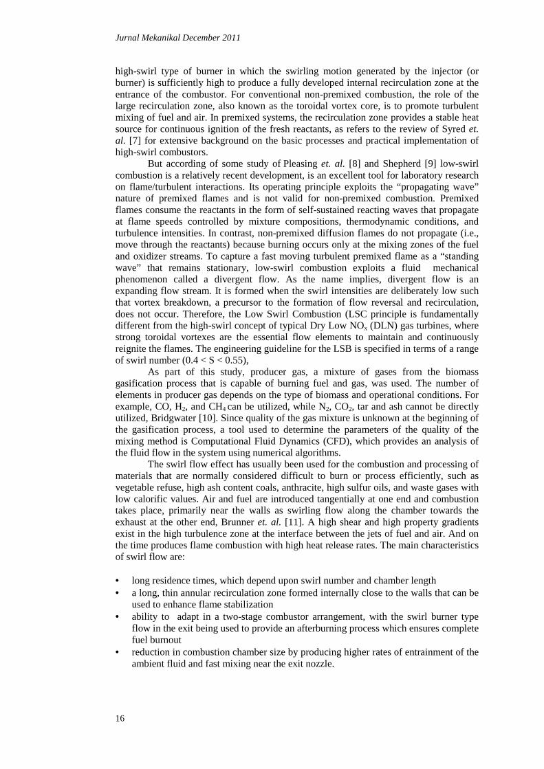
i. Previous testing using the latest gas burner version shows that the quality ofthe gas flame is still low (yellow-red color dominates the gas-flame), as indicated
in Figure 1.
Figure 1: Gas burner flame with yellow-red color domination
ii. Heat release rate of the flame, flame performance and measurement of product gas flame, such as CO, H2, CH4, N2, CO2, are not yet identified.

Jurnal Mekanikal December 2011
19
The objective of the study is to determine how to improve the performance of the current gas burner, including the quality of flame, flame temperature, heat transfer rate, efficiency, and reduction of CO and NOx emissions.
2.0 RESEARCH METHODOLOGY Measurements and predictions for incorporating the swirl burner with the biomass gasification system were conducted in the current study at the University of Indonesia, Department of Mechanical Engineering, Gasification Laboratory. Equipment used in this research includes a downdraft gasifier, a cyclone, and a venturi scrubber as gas cleaning equipment, a gas holding tank, a gas burner, and a combustion unit.
2.1 Simulation Procedure The turbulence model of the renormalized group theory (RNG) k-ε consists of two equation models in which the transport equations for two scalar quantities (the turbulent kinetic energy, k and its dissipation rate, ε ) are used to describe the production, diffusion and dissipation of turbulence. The RNG k-ε model belongs to the k-εfamily of turbulence models. Unlike the standard k-ε, the RNG k-ε model was derived using a statistical technique called the Renormalization Group Method model has an additional rate-of-strain term in the transport equation ε, to provide a more accurate prediction of swirl than in standard k-ε. When the RNG k-ε model was implemented, the swirl dominated flow option was used. This option establishes the swirl constant, αo, 0.35.
(a)
(b)
Figure 2 : Model of fuel gas burner system (a) and overview of swirl burner (b)
Jurnal Mekanikal December 2011
20
Dimensions of the gas burner system mm and length of 200 mmmm, and burner with exit area of 166 mmCombustion chamberswirl is 60 mm longand 56 mm diameter.length. Solid model for the gas bu
To simplify the simulation, system was used for modeling purposes.burner (tetrahybrid mesh)quadrilateral mesh. This geometric model makeof FLUENT to represent the g
Figure 4 : Meshing
The computational model predict the effect of the different swirler field. Three variationvane swirlers with 6, 8 and 10 vanes,biomass gasifier system. was required, it was
The following conservation, RNG used in the model’s solution
December 2011
Dimensions of the gas burner system are as follows: fuel inlet 200 mm; tangential air inlet with diameter of 22 mm and
urner with diameter entrance area of 96 mm, length of 155 mm166 mm. Diameter of mixing chamber 102 mm; length is
Combustion chamber’s length is 952 mm and diameter is 422 mmlong, with blades at a tilt angle of 30o, outer dimensions are
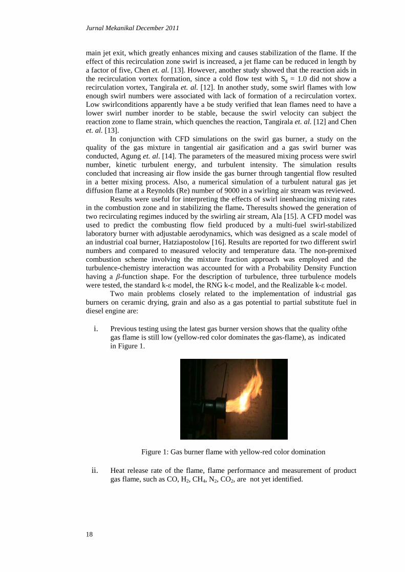
and 56 mm diameter. Dimensions of cones used 30 mm diameter of and 21 mm side length. Solid model for the gas burner system is shown in Figure 3.
Figure 3 : Solid model gas burner system
simplify the simulation, only the swirler burner component of the gasifier system was used for modeling purposes. A computational mesh pattern of this swirler
(tetrahybrid mesh), is constructed in Figures 4a and 4b. Note use of quadrilateral mesh. This geometric model makes use of the advanced gridding capabilities of FLUENT to represent the geometric patterns as closely as possible
(a)
(b)
Meshing results with interval size 30 (a); Plane x=0.2 and
The computational model was applied to the current 3-D gas burner predict the effect of the different swirler values of the gas burner to the
hree variations in swirler value were employed in this investigation 6, 8 and 10 vanes, respectively). These gas burner
biomass gasifier system. For the current research, simplification of the gas burner not necessary for the entire biomass gasifier to be
he following equations of mass conservation, momentum conservation, energy NG turbulence and displacement, the compounds (species
sed in the model’s solution :
as follows: fuel inlet with diameter of 66 angential air inlet with diameter of 22 mm and length of 102
155 mm, and diameter ; length is 166 mm.
422 mm. The dimension of outer dimensions are 60 mm width
diameter of and 21 mm side
component of the gasifier A computational mesh pattern of this swirler
Note use of triangular and use of the advanced gridding capabilities
as closely as possible.
(b)
and x=0.5 m (b)
D gas burner system to burner to the system’s flow
in this investigation (i.e., fixed hese gas burners were parts of the
, simplification of the gas burner model to be simulated.
of mass conservation, momentum conservation, energy he compounds (species transport) are

Jurnal Mekanikal December 2011
21
mSt
=∇+∂∂
).( υρρ r (5)
Fgpt
rrrrr ++−∇=∇+∂∂ ρυυρυρ ).()( (6)
hjj
j SJhpEEt
+−∇=+∇+∂∂
∑ ).())(.()( ρυρ r (7)
kMbkj
kj
ii
SYGGx
k
xku
xk
t+−∈−++
∂∂
∂∂=
∂∂+
∂∂ ρµαρρ )()()( (8)
iiiii SRJYYt
++−∇=∇+∂∂ rr
.).()( υρρ (9)
where v is velocity vector (m/s), ρ is mass of gas type of gas (kg/m3), Sm is source term due to the addition to the phase of continuous from dispersed phase, P is static pressure
(Pa),τr is stress tensor (Pa) , ρ gr
is body gravitational force (N), Fr
is external body force (N), E is enthalpy (J/kg), h is the enthalpy compound (J/kg), Ji is the mass flow rate diffusion compound i (kg/m2s2), source term Sh is the heat induced reaction, k is turbulence kinetic energy (m2/s2), u is velocity (m/s), µeff is dynamical effective viscosity (kg/ms), Gk represents generating turbulent kinetic energy due to velocity gradients, Gb is turbulent kinetic power due to buoyancy, ε is turbulent dissipation rate (m2/s3), Ym represents influence of dilatation fluctuations of compressible turbulent dissipation rate, Sk stands for source terms in the specified user, Yi is mass fraction of each compound, Ri is the net production rate of compound i by chemical reaction (kg/m3s2), and Si is the source term due to the addition of a specific phase i. 2.1.1 Finite Rate Reaction This model was implemented on the burner-nozzle zone because premixing of the gas mixture occurred before entering the burner-nozzle. Methane combustion modeling was necessary to solve this reaction and was simulated by a two-step chemical mechanism. The methane two-step combustion model consisted of the following reactions:
CH4 + 1 ½ O2 ⇒ CO + 2 H2O (10)
CO + ½ O2 ⇒ CO2 (11)
Followed by hydrogen reaction: H2 + ½ O2 ⇒ H2O (12) Rate expressions for the forward reactions are generalized in Arrhenius form, based on reactant concentrations [Ri] and temperature T: Ref = -ν’ i,k ATn[Ra]
a [Rb]b exp{EA/RT} (13)

Jurnal Mekanikal December 2011
22
where -ν’ i,k is the molar stoichiometric coefficient for species i in reaction k (positive values for reactants, negative values for products), A is pre-exponential factor (consistent units), T is temperature (̊K), n is temperature exponent (dimensionless), a and b are species exponents, and EA is activation energy for the reaction (J/kmol).
The influence of turbulence time scale k/ε on the reaction rate was taken into account by employing the Magnussen and Hjertager model (1976) [17] :
RRk = -4νk Miρε⁄krr
r
M
m
ν (14)
RPk = 2 νk Miρε⁄k PPP
PP
M
m
υ∑∑
(15)
where Mi is molecular weight of species i (kg/kmol), mp is particle mass (kg), mr,P is mass fraction of a particular reactant R and Product (P), � �s density (kg/m3). The eddy breakup model relates the rate of reaction of dissipation of the Reactant (R) and Product (P),containing eddies, ε /k represents the time scale of the turbulent eddies following the eddy breakup model of Spalding (1972) [17].
The model was applied, without modification, to the combusting. This ensured a consistent representation of the flow and combustion physical processes so that the comparisons between two cases would be insensitive to the particular turbulence and combustion models employed. By assuming steady state, the component of change according to time (∂/∂t) in the equation above was removed. 2.1.2 Boundary Condition The boundary condition is as follows:
• Composition of the gas mass fraction in the producer gas consists of: CO (25 %), H2 (12 %), CH4 (1.5 %), and N2 (51.5 %)
• Mean velocity of producer gas was 5 m/s for biomass • Tangential air injection velocity was 9.7 m/s for biomass • Producer gas temperature is 200oC and tangential air temperature was 27oC.
2.2 Experimental Set-Up The gasification process was conducted on a downdraft gasifier and was equipped with a cyclone, wet scrubber, and gas holding as in Figure 5. Air flow rate for the gasification process is 190 lpm and fuel used is biomass (coconut shell), with each analysis shown in Table 1.
Table 1: Proximate and ultimate analysis of coconut shells
5.3 C 47.59
70.7 H 6.0
Ash 6.26 O 45.52
17.54 N 0.22
22 S 0.05
Proximate analysis (% weight)
Moisture
Volatile Matter
Fixed Carbon
Low Heating Value (kj/kg)
Ultimate Analysis (% weight)

Jurnal Mekanikal December 2011
23
Figure 5 : Gasification and gas burner system
A gas swirl burner with a diameter of 66 mm was used and three different vanes of
6, 8 and 10 blades were utilized. The material used for the swirl burners was mild steel. The material could resist temperatures below 1000 K in continuous operation.
Figure 6 : Combustion equipment Figure 7 : Schematic of the gas burner
In Figure 6, the gas burner is located inside the combustion unit, which is attached by two thermocouples placed in a parallel position. For cooling purposes, the outside of the combustion unit was blanketed by water jacket, to absorb heat.
Table 2 : Operating conditions for turbulent premixed flames
Flow Parameter
Swirl-vane blades 6 8 10
Equivalence Ratio, φ 1.25 – 1.84 Nominal Heat Release, kW 12.22 Gas Flow Rate, kg/hr 28.8 Flame temperature, oC 750 780 770 Temperature at burner exit, oC 490 475 450 Range of secondary Air Flow Rate, kg/h 936 Combustor Pressure, atm Atmospheric pressure Swirl Vane Angle 30o
TC 2 position
Gasification reactor
Particle Cleaner
Gas cooler and Tar trap
Stabilizer for Flow Gas Producer
Gas Burner
Glass window
TC1 position
Gas Burner

Jurnal Mekanikal December 2011
24
Producer gas from the primary chamber was kept constant at 28.8 kg/h. Flow rate of secondary air remained constant at 936 kg/h. The operating conditions for the turbulent premixed flames considered in the present study are summarized in Table 2 above. The nominal heat release rate is obtained by multiplying the fuel mass flow rate by its nominal heating value of 4,482 kJ/m3. 3.0 RESULTS AND DISCUSSION 3.1 Gasification Test and Simulation Before Modification of Swirl Vane Blades Gasification process was carried out using biomass fuels (coconut shells). Gas compostion have taken from gasification process using gas sample bag and be analyzed using HP 6890 SERIES Gas Chromatography (GC) with standard method of GPA 2261. Gas composition resulting from the gasification process is shown in Table 3.
Table 3 : Composition of Biomass Gasification Gas
Gas Composition
CO 24.7%
CH4 6.7%
H2 15.9%
CO2 11%
O2 1.2%
N2 41% 3.1.1 Experimental Results From the results of experiments carried out on the existing gas burner (before modification) on a secondary air flow rate with constant gas flow, the most optimal condition of secondary air flow rate was obtained at the flow rate of 294 lpm, with the results for biomass shown in Table 4.
Table 4 : Existing gas burner test results at optimum condition (before modification)
Parameter Value
Thermocouple 1 719 0C
Thermocouple 2 657 0C
Heat Release 10.2 kJ/s
Efficiency 80.5%
CO 0.05 % Vol
NOX 1.4 ppm
3.1.2 Simulation Results Simulations were carried out on existing gas burner using the swirl blades of 6 and outer diameter of 66 mm (before modification). Tangential air velocities used were 9.7 m/s, 10.7 m/s, and 11.7 m/s, velocity of fuel gas from biomass gasification was 5 m/s.

Jurnal Mekanikal December 2011
25
3.1.2.1 Flame Temperature The simulation results identify the temperatures at thermocouple 1 for air velocity of 9.7 m/s at 1,130 K (857 oC) and at 1,009 K (736 oC) for thermocouple 2, as shown in Figure 8. Contours of velocity in a combustion unit distribution are shown in Figure 9. The simulation results show about 10% higher values at different flowrates, as compared to the experiment for biomass fuel.
Figure 8 : Thermocouple temperatures distribution on 1 and 2 of the simulation
Figure 9 : Contour velocity on the air speed tangential 9.7 m/s
3.2 Enhancing the Performance of the Gas Burner Results from experimentation on the existing burner gas showed that a maximum temperature can be produced at around 700oC. Performance of the gas burner should be improved by reducing the diameter of the producer gas path and varying the number of blades in the swirl burner. In this study, the diameter was reduced by 10 mm from initial conditions of 66 mm to 56 mm. Variations of 6, 8 and 10 blades were used. 3.2.1 Modeling and Blade Variation of the Swirl Burner Swirl was used for the optimization process of the gas burner in a solid, first drawn and modeled in 3D as in Figure 10 to simplify the process of simulation and manufacturing.

Jurnal Mekanikal December 2011
26
Figure 10 Model : Swirler vane blades variation of 6, 8 and 10.
3.2.2 Simulation and Experiment Results with New Gas Burner 3.2.2.1 Results Simulation Figure 11 shows no significant difference in temperatures indicated by each type of swirl possibly because the plane was only a few centimeters from the cones so that the flame that formed possessed the same average temperature contours. Maximum temperature was approximately 900oC for thermocouple 1 and 700oC for thermocouple 2.
(a) (b)
Figure 11 : Temperature distribution for distance (a) X = 0.2 m (TC1) and (b) X=0.5 m (TC2)
Temperature distribution as show in Figure 11 shows a high concentration of
temperature near the middle area combustion unit, or in the radial direction. The graph on Figure 11a shows TC1 at x = 0.2 m, compared to TC2 at x = 0.5 m, gives higher temperature. Furthermore, TC1 indicates in the center of combustion unit, for Swirl 8, has an interesting temperature distribution behavior. It shows that the distribution at the center does not reduce immediately, while for swirl vanes 6 and 10 shows the distribution in the center reduce immediately. It is possible, that the momentum of mixing process of swirl vanes 8 gives high enough kinetic reaction of combustion process.
Predicted flame distribution shown in Figure 12 indicates that increasing the blade number strengthens the kinetic energy of the mixing process. High swirl number strengthens the kinetic reaction. But for swirl vane blades 8, the combustion process after cones produces immediate combustion process, while for swirl vanes 6 and 10, gives different results, namely, a late combustion process. This perhaps, presents a slowly kinetic reaction between gas and air near cones. The strength of swirl vanes 8 produces a flame with a high Re number.

Jurnal Mekanikal December 2011
27
Figure 12 : Predicted temperature on axial plane:swirls 6, 8 and 10
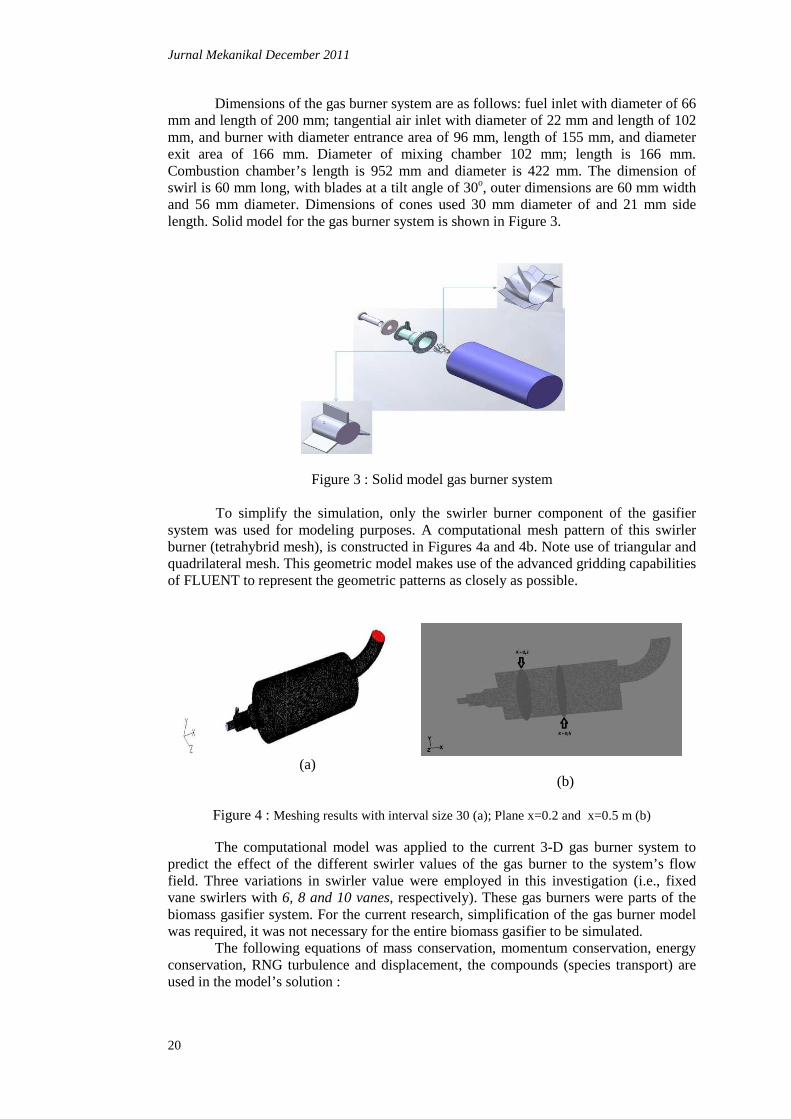
3.2.2.2 Manufacturing Swirl Gas Burner After using simulation to predict the temperatures and composition of the CO gas, the fabrication of the hub, cones and the swirl blades of the gas burner were done as shown in Figure 13 and Figure 14. This followed by a serial of laboratory tests and compared with the simulation results.
Figure 13 : Hub and cones gas burner
Hub
cones
Jurnal Mekanikal December 2011
28
Figure 14 : Swirlers with 6, 8 and 10 vane blades
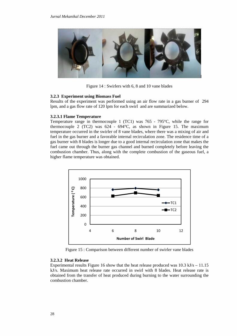
3.2.3 Experiment using Biomass Fuel Results of the experiment was performed using an air flow rate in a gas burner of 294 lpm, and a gas flow rate of 120 lpm for each swirl and are summarized below. 3.2.3.1 Flame Temperature Temperature range in thermocouple 1 (TC1) was 765 - 795°C, while the range for thermocouple 2 (TC2) was 624 - 694°C, as shown in Figure 15. The maximum temperature occurred in the swirler of 8 vane blades, where there was a mixing of air and fuel in the gas burner and a favorable internal recirculation zone. The residence time of a gas burner with 8 blades is longer due to a good internal recirculation zone that makes the fuel came out through the burner gas channel and burned completely before leaving the combustion chamber. Thus, along with the complete combustion of the gaseous fuel, a higher flame temperature was obtained.
Figure 15 : Comparison between different number of swirler vane blades
3.2.3.2 Heat Release Experimental results Figure 16 show that the heat release produced was 10.3 kJ/s – 11.15 kJ/s. Maximum heat release rate occurred in swirl with 8 blades. Heat release rate is obtained from the transfer of heat produced during burning to the water surrounding the combustion chamber.
0
200
400
600
800
1000
4 6 8 10 12
Te
mp
era
ture
( 0
C)
Number of Swirl Blade
TC1
TC2

Jurnal Mekanikal December 2011
29
Figure 16 : Heat release at different number of swirler vane blades 3.2.2.3 Combustion Efficiency Combustion efficiency is the result of color content in producer gas is shared with heat release from the combustion process. Experimental results show improved efficiency from 83.1% to 85.5% for the producer gas as shown in Figure 17. Maximum combustion efficiency occurred for the swirler with 8 blades. Oxygen levels in the flue gas affect the efficiency; less oxygen in exhaust gas promotes greater combustion efficiency.
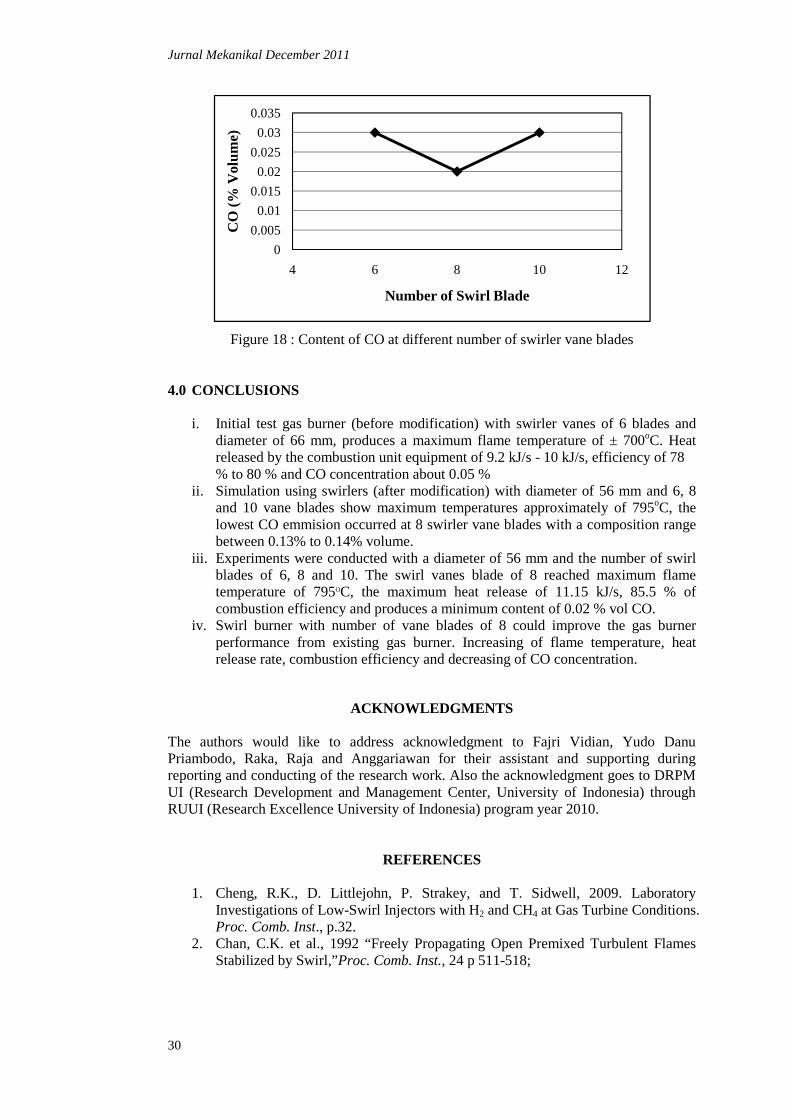
Figure 17 : Combustion efficiency at different number of swirler vane blades 3.2.2.4 Composition CO CO content in flue gas was between 0.02 - 0.03 % as shown in Figure 18. The content of CO generated is still below the 4.5 % volume emission standards for motor vehicle exhaust emission levels of CO gas. Swirl vanes with 8 blades appear to reduce volume content levels of CO emissions by at least 0.02 % by producing turbulence leading to more complete combustion.
9.5
10
10.5
11
11.5
4 6 8 10 12
Hea
t Rel
ease
Rat
e (k
J/s)
Number of Swirl Blade
81
82
83
84
85
86
4 6 8 10 12
Com
bust
ion
Eff
icie
ncy
(%)
Number of Swirl Blade
Jurnal Mekanikal December 2011
30
Figure 18 : Content of CO at different number of swirler vane blades 4.0 CONCLUSIONS
i. Initial test gas burner (before modification) with swirler vanes of 6 blades and diameter of 66 mm, produces a maximum flame temperature of ± 700oC. Heat released by the combustion unit equipment of 9.2 kJ/s - 10 kJ/s, efficiency of 78 % to 80 % and CO concentration about 0.05 %
ii. Simulation using swirlers (after modification) with diameter of 56 mm and 6, 8 and 10 vane blades show maximum temperatures approximately of 795oC, the lowest CO emmision occurred at 8 swirler vane blades with a composition range between 0.13% to 0.14% volume.
iii. Experiments were conducted with a diameter of 56 mm and the number of swirl blades of 6, 8 and 10. The swirl vanes blade of 8 reached maximum flame temperature of 795OC, the maximum heat release of 11.15 kJ/s, 85.5 % of combustion efficiency and produces a minimum content of 0.02 % vol CO.
iv. Swirl burner with number of vane blades of 8 could improve the gas burner performance from existing gas burner. Increasing of flame temperature, heat release rate, combustion efficiency and decreasing of CO concentration.
ACKNOWLEDGMENTS The authors would like to address acknowledgment to Fajri Vidian, Yudo Danu Priambodo, Raka, Raja and Anggariawan for their assistant and supporting during reporting and conducting of the research work. Also the acknowledgment goes to DRPM UI (Research Development and Management Center, University of Indonesia) through RUUI (Research Excellence University of Indonesia) program year 2010.
REFERENCES
1. Cheng, R.K., D. Littlejohn, P. Strakey, and T. Sidwell, 2009. Laboratory
Investigations of Low-Swirl Injectors with H2 and CH4 at Gas Turbine Conditions. Proc. Comb. Inst., p.32.
2. Chan, C.K. et al., 1992 “Freely Propagating Open Premixed Turbulent Flames Stabilized by Swirl,”Proc. Comb. Inst., 24 p 511-518;
0
0.005
0.01
0.015
0.02
0.025
0.03
0.035
4 6 8 10 12
CO
(% V
olum
e)
Number of Swirl Blade

Jurnal Mekanikal December 2011
31
3. Bedat, B. and Cheng, R.K., 1995.“Experimental Study of Premixed Flames in Intense Isotropic Turbulence,” Combustion and Flame 100, no. 3 p 485-494;
4. Cheng, R.K., 1995, “Velocity and Scalar Characteristics of Premixed Turbulent Flames Stabilized By Weak Swirl,” Combustion and Flame 101, no.1-2 p.1-14.
5. Surjosatyo, A. and Ani, F.N., 2005. Experimental and Prediction of the Development of Low-Calorific Swirl Burner, Reric International Energy Journal, Asian Institute Technology (AIT), Bangkok,Vol 6.No 2.
6. Surjosatyo, A. and Ani, F.N., 2002. “Development of Swirl Burner Incorporated with a Biomass Combustion System”. 6thAsia-Pacific International Symposium
on Combustion and Energy Utilization, Kuala Lumpur, Malaysia. 7. Syred. N. and J.M. Beer, 1974. “Combustion in Swirling Flow: A Review,”
Combustion and Flame 23 p. 143-201. 8. Plessing. T. et al., 2000. “Measurement of the Turbulent Burning Velocity and
the Structure of Premixed Flames on a Low Swirl Burner,” Proc. Comb. Inst. 28 p 359-366.
9. Shepherd. I. G. et al., 2002 “Premixed Flame Front Structure in Intense Turbulence,”Proc. Comb. Inst. 29 p.1833-1840.
10. Bridgwater, A.V. 1995. The technical and economic feasibility of biomass gasification for power generation. Fuel. Vol 74 No.5, pp. 631-653.
11. Brunner, C.R. 1985. Hazardous Air Emission form Incinerator, Chapman & Hall. 12. Tangirala, V., Chen, R. H., and Driscoll, J. F., 1987, ”Effect of Heat Release and
Swirl on the Recirculation within Swirl-Stabilization Flames,” Combustion Science and Technology, Vol. 51, pp. 75-95.
13. Chen, R. H., and Driscoll, J. F., 1988, “The Rule of the Recirculation Vortex in Improving Fuel-Air Mixing within Swirling Flames,” Twenty-Second Symposium (International) on Combustion, Combustion Institute, Pittsburgh, pp. 531-440.
14. Agung Hidayat and A. Surjosatyo, 2008. Cold flow simulation on a Biomass Gasification. Final Year Project, Departemen Teknik Mesin, FT, UI, Indonesia.
15. Ala Qubbaj, 2005. Numerical Simulation of Natural Gas-Swirl Burner. Final Technical Report, University of Texas Pan American.
16. Hatziapostolou, A., et. al., 2006. CFD modeling of the swirl-stabilised flame produced by a laboratory-scale combustor: selection of the turbulence model. Proceedings of the 4th WSEAS Int. Conf. on Heat Transfer, Thermal Engineering and Environment, Elounda, Greece, pp 83-88.
17. Fluent Inc, 6.3. , “User Guide”, Fluent Incorporated, Lebanon