investigation of axial heat conduction flux inwjert.org/download/article/14042016/1462011245.pdf ·...
TRANSCRIPT

www.wjert.org
108
Yadav et al. World Journal of Engineering Research and Technology
INVESTIGATION OF AXIAL HEAT CONDUCTION FLUX IN
RECTANGULAR PARALLEL FLOW MICROCHANNEL HEAT
EXCHANGER WITH NO-SLIP FLOW
Avinash Yadav*1, Dr. Satyendra Singh
2, Ravi Kumar
3 and Lokesh Chandra Joshi
4
1M.Tech Scholar, Mechanical Engineering Department, BTKIT, Dwarahat, Uttarakhand.
2Associate Professor, Mechanical Engineering Department, BTKIT, Dwarahat, Uttarakhand.
3Assistant Professor, Mechanical Engineering Department, BTKIT, Dwarahat, Uttarakhand.
4GBPUAT, Pantnagar, Uttarakhand.
Article Received on 16/03/2016 Article Revised on 04/04/2016 Article Accepted on 24/04/2016
ABSTRACT
In this paper the axial heat conduction in a rectangular microchannel
heat exchanger is numerically investigated. The flow is taken as
laminar, 3D, incompressible, single-phase, steady state flow. The
behavior of axial heat conduction in the separating wall for different
Reynolds number is studied. The solution was obtained by solving the
continuity and Navier– Stokes equations for the hot and cold fluids by using the pressure-
correction method to obtain the velocity distribution, and then the energy equations were
solved for the two fluids and the separating wall simultaneously to obtain the temperature
distribution in FLUENT code 16.0. Various parameters that can have effect on the axial heat
conduction were investigated. In the result it is observed that, the axial heat conduction plays
an important role at the entrance of the channel, velocities of hot fluid and cold fluid are
increasing at the entrance of the channel as increases in Reynolds number.
KEYWORDS: Microchannel heat exchanger, No-slip, Reynolds number, Axial heat
conduction flux, Parallel flow.
INTRODUCTION
Micro-channels are found in many systems where extremely efficient heat and mass transfer
processes occur. Across the wall of the channel this transfer movement occurs, whereas the
ISSN 2454-695X Research Article wjert, 2016, Vol. 2, Issue 3, 108 -119
World Journal of Engineering Research and Technology WJERT
www.wjert.org SJIF Impact Factor: 3.419
*Corresponding Author
Avinash Yadav
M.Tech Scholar,
Mechanical Engineering
Department, BTKIT,
Dwarahat, Uttarakhand.

www.wjert.org
109
Yadav et al. World Journal of Engineering Research and Technology
flow takes place through the cross-sectional area of the channel. The smaller channel
dimension gives higher heat transferal performance although it is attended high pressure drop
per unit length. The high flux heat distribution from high-speed microprocessors provided the
focus for studies on heat transfer in microchannel. The higher volumetric heat transfer
densities postulate advanced manufacturing techniques and lead to more complex multiplex
designs. An optimum balance for each application leads to contrary channel dimensions.
Heat transfer investigation in microchannel flow has drawn great attention due to its
extensive applications in micro heat exchangers and micro fuel cells. Researchers have been
dedicated in the investigation using theoretical analysis, numerical and experimental
formulation.
However if the Peclet number is small in the flow, axial heat conduction is important in the
fluid.
Liu and Lee.[1]
The rapid development of modern electronics industry has necessitated
effective cooling techniques which are capable of dissipating ultra-high heat flux of about
100W/cm2 from the highly integrated microelectronics systems to ensure a stable and
optimal operation. Moharana et.al[2]
studied axial heat conduction effect in microchannel
flow using thermocouples with parallel channel design and reported that Non-linear fluid and
surface temperature distributions and lower Nu number.
NOMENCLATURE
H Channel height, m
B Channel base, m
Cc Heat capacity of cold fluid, W/K
Ch Heat capacity of hot fluid
Cp Specific heat at constant pressure, kg/k
Dh Hydraulic diameter, m
k Thermal conductivity, W/mK
L Length of the channel, m
m Mass flow rate, kg/s
p Pressure, Pa
q Heat transfer rate, W
qmax Maximum heat transfer rate, W
T Temperature, K
vi Fluid y-component velocity, m/s
wi Fluid z-component velocity, m/s
x Axial coordinate, m/s
x* Dimensionless axial distance, m/s
y Vertical coordinate, m/s
z Horizontal coordinate, m/s
GREEK SYMBOL
ɛ Heat exchanger effectiveness
ρ Density, kg/m3
µ Dynamic viscosity, Ns/m2
SUBSCRIPTS
c Cold fluid
h Hot fluid
i Inlet
max Maximum value
min Minimum value
o Outlet
s Solid

www.wjert.org
110
Yadav et al. World Journal of Engineering Research and Technology
Jian et.al.[3]
shows that microchannel heat exchangers are gives very high heat transfer area
per unit volume over a conventional heat exchangers, it means the overall heat transfer
area per unit volume can be greater than 100MW/m3k. They show that the performance of
heat exchanger is dependent on the mass flow rate and fluid properties. Wang and Shyu.[4]
experimentally studied the effect of thermal conductivity of wall material and channel size in
microchannel heat exchanger for hot and cold water loop. They concluded that wall material
and channel size strongly influence the capability of heat transfer in microchannel heat
exchanger. Ravigururajan et.al.[5]
experimentally studied the performance characteristics of
single phase flow parallel type microchannel heat exchanger using Refrigerant-134 as a fluid
in experimental set up and concluded that the heat transfer coefficient increases in the
thinning of a boundary layer in the narrow channels, with low thermal resistance.
Kroger[6]
solved the governing equation for counter flow heat exchanger (two streams) with
considering the effect of axial heat conduction in the channel, he used the one dimensional
plate which separating the two fluids and showed the closed form solution for finding the
effectiveness of a heat exchanger and also showed that effectiveness of the heat exchanger is
largely dependent on the on the axial heat conduction in the separating wall. Yin and Bau.[7]
study the effect of axial heat conduction on the performance of microchannel heat exchanger
between parallel plates and circular pipe and showed that at the entrance region axial heat
conduction plays an important role.
Stief et.al[9]
investigated in the microchannel heat exchanger with the effect of solid thermal
conductivity and concluded that heat transfer efficiency improve with reduction of wall
material thermal conductivity due to influence of axial heat conduction in the separating wall.
Neti and Eichhorn[8]
used Finite difference method to solve hydro dynamically and thermally
developing flow in a square duct. They assumed that in the axial direction pressure gradient
linearly varied and neglect the axial momentum and energy diffusion. Venkatarathnam and
Narayanan[10]
also concluded that heat exchanger performance largely dependent on the heat
conduction that takes place through the wall of a heat exchanger used in a miniature
Refrigerator.
Al-bakhit and Fakheri[11]
numerically investigated the parallel flow microchannel heat
exchanger with rectangular ducts. They reported that effectiveness of a heat exchanger will
be independent of the thermal conductivity of wall and high conductivity material will not
effect the effectiveness of heat exchanger. Al-bakhit and Fakheri[12]
investigated in

www.wjert.org
111
Yadav et al. World Journal of Engineering Research and Technology
rectangular ducts parallel flow microchannel heat exchanger and showed that the overall heat
transfer coefficient is rapidly changed along the length of a heat exchanger in the order of
0.03 for Greatz number. Hasan.[13]
made numerical investigation for the study of counter flow
microchannel heat exchanger with different geometries and fluids. He found that the
existence of axial heat conduction leads to reduction in the effectiveness of counter flow
microchannel heat exchanger with square shaped channel.
THEORY AND PROBLEM DISCUSSION
Fig.1 represents the unit cells of microchannel array. The schematic diagram shows the two
isosceles right triangular channels and separating solid wall between them which separates
the hot and cold fluid and play as a role of interfaces between the fluids.
Fig. 1 schematic diagram of parallel flow microchannel heat exchanger.
3cm (L) is the channel length, 195µm (B) is a base of a channel, 195µm (H) is the height of
the channel, 70µm (t) is the thickness of the solid wall, Z is projected distance and hydraulic
diameter (Dh) 114µm. The cold fluid enters in the upper channel and the hot fluid enters the
lower channel with uniform velocity and uniform temperature. The numerical procedures are
based on the physical and geometrical assumption of the channel. The following assumptions
are taken for the present model:
The fluids are incompressible (water is used as a working fluid).
The flow is laminar and steady.
The fluid is a continuous media, the Knudsen number is small taking as no-slip
condition.
There is no heat generation to/from the ambient.
Three dimensional flow.
The pressure gradient is an axial direction only.
www.wjert.org
112
Yadav et al. World Journal of Engineering Research and Technology
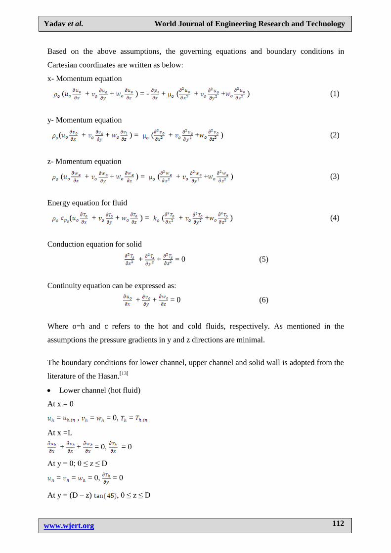
Based on the above assumptions, the governing equations and boundary conditions in
Cartesian coordinates are written as below:
x- Momentum equation
( + + ) = - + ( + + ) (1)
y- Momentum equation
( + + ) = ( + + ) (2)
z- Momentum equation
( + + ) = ( + + ) (3)
Energy equation for fluid
( + + ) = ( + + ) (4)
Conduction equation for solid
+ + = 0 (5)
Continuity equation can be expressed as:
+ + = 0 (6)
Where o=h and c refers to the hot and cold fluids, respectively. As mentioned in the
assumptions the pressure gradients in y and z directions are minimal.
The boundary conditions for lower channel, upper channel and solid wall is adopted from the
literature of the Hasan.[13]
Lower channel (hot fluid)
At x = 0
= , = = 0, =
At x =L
+ + = 0, = 0
At y = 0; 0 ≤ z ≤ D
= = = 0, = 0
At y = (D – z) , 0 ≤ z ≤ D

www.wjert.org
113
Yadav et al. World Journal of Engineering Research and Technology
= = = 0
= , =
At z = 0, 0 ≤ y ≤ D
= = = 0, = 0
At y = (D – y) , 0 ≤ y ≤ D
= = = 0
= , =
Upper channel (cold fluid)
At x = 0
= , = = 0, =
At x = L
+ + = 0, = 0
At y = (D – z) , S ≤ z ≤ (D + S)
= = = 0
= , =
At z = D + S
= = = 0
= 0
Separating wall (solid)
At x = 0
= 0
At x = L
= 0
At y = (D – z) , 0 ≤ z ≤ D
= , =
At z = y , S ≤ y ≤ (D + S)
= , =
At z = 0; D ≤ y ≤ (D + S)

www.wjert.org
114
Yadav et al. World Journal of Engineering Research and Technology
= 0
At z = (D + S), 0≤ y ≤ S
= 0
At y = (D + S), 0 ≤ z ≤ S
= 0
At y = 0, D ≤ z ≤ (D + S)
= 0
Then, the parameters such as the axial heat conduction q’’ in the separating wall, the amount
of heat transferred between two fluids and the effectiveness ɛ which is the ratio of actual heat
transfer to the maximum possible heat that can be transferred can be calculated from Ashman
and Kandlikar.[14]
:
ɛ = / (7)
= ( - ) = ( - ) (8)
For convenience, the flow rates and specific heats are lumped together, and the term product
of the capacity rates is
= and = (9)
For < ,
= ( - ) (10)
Otherwise
= ( - ) (11)
Thus
= ( - ) (12)
Then the effectiveness is
ɛ = = (13)
For the axial heat conduction in section x
= ( )x (14)

www.wjert.org
115
Yadav et al. World Journal of Engineering Research and Technology
Fig. 2 Schematic of separating wall.
Where, is the average solid temperature in certain sections and at the next section as
shown in Fig. 2.
RESULTS AND DISCUSSION
Axial heat conduction on a separating wall in a microchannel heat exchanger is studied for
different Reynolds numbers. Water is used as a working substance for both channels in the
microchannel heat exchanger. The inlet temperature of cold fluid is 300oK, temperature of
hot fluid at inlet 346oK. The processing of developing velocity flow field was simulated in
the commercial accessible CFD package of ANSYS FLUENT 16.0.
Comparisons of temperatures for hot and cold fluids with length of the channel as shown in
figure 3.
Fig. 3 comparison of mean temperatures for cold and hot fluid along length of present
model and data of Al-bakhit and Fakheri.[12]
The present model for the hot, cold fluids is validated with those of Al-bakhit and Fakheri[12]
and are found to be in good agreement.

www.wjert.org
116
Yadav et al. World Journal of Engineering Research and Technology
Fig. 4 velocity along the length of the channel for different values of Reynolds number.
The variations of center axial velocities with length of the channel are calculated. It is
observed from the obtained result at the entrance of the channel the velocities are increasing
as the Reynolds number increasing and reaches its maximum value as shown in figure 4.
Fig.5 Temperatures of cold fluid, separating wall, hot fluid along the length of the
channel.
Figure 5 disputes the heat transfer process in the channel from the result it is noted that the
temperature of cold fluid is growing and the temperature of hot fluid is diminishing along the
length of the channel. So it can be established that the heat transfer takes place inside a
channel from hot fluid to cold fluid and the temperature of solid wall is among them.

www.wjert.org
117
Yadav et al. World Journal of Engineering Research and Technology
Fig. 6 axial heat conducted and heat conduction between fluids along the length of a
channel.
Figure 6 indications the prominence of axial heat conduction in a microchannel heat
exchanger and designates the scattering of flux of heat transferred and axial heat conduction
flux between two fluids along the length of a channel in the direction of flow. From the
outcome it is prominent that, the amount of heat conducted in the axial direction of the solid
wall separating the fluids cannot be ignored due to its significant value.
Fig. 7 variation of axial heat conduction for different values of Reynolds along the flow
direction.
Figure 7 demonstrate the distribution of longitudinal axial heat conduction flux in the
separating wall along the heat exchanger for different Reynolds numbers. The result indicate
for all Reynolds number axial heat conduction flux is high at the entrance region, it means the
maximum heat transfer occurs at the entrance region and as a result a maximum value of
axial heat conduction is obtained in this region. Also it can be seen the axial heat conduction
flux improved with growing the value of Reynolds number.

www.wjert.org
118
Yadav et al. World Journal of Engineering Research and Technology
CONCLUSIONS
From the acquired results we resolved that velocities of hot and cold fluids are increasing at
the entrance region of the channel and achieves its maximum value. It also be eminent that
for different values of Reynolds number the velocities are growing. The heat transfer occurs
from hot fluid to the cold fluid due to the separating wall between them and the significant
temperature of the separating wall. The increasing amount of heat transfer and increasing
effect of Reynolds the part of axial heat conduction increased.
REFERANCES
1. Dong Liu, Poh-Seng Lee, (2003). Numerical investigation of fluid flow and heat transfer
in microchannel heat sink. Project Report, ME 605 Convection of Heat and Mass,
December 09, West Lafayette, IN, USA.
2. Moharana, K.M., Agarwal, G., Khandekar, S., Axial conduction in single-phase
simultaneously developing flow in a rectangular mini-channel array, Int. J. Thermal Sci.,
2011; 50: 1001e1012.
3. Jian, Pei-Xue, Fan, Ming-Hong, Si, Guang-Shu, Ren, Ze-Pei, Thermal-hydraulic
performance of small scale microchannel and porous-media heat exchangers.
International Journal of Heat and Mass Transfer, 2001; 44: 1039–1051.
4. Wang, H.J., Shyu, J.R., (1991) Thermal–hydraulic characteristics of micro heat
exchangers, in: ASMEWinter Annual Meeting, Atlanta, GA, USA, 1–6 December.
5. Ravigururajan, S.T., Cuta, J., McDonald, E.C., Drost, K.M., Singlephase flow thermal
performance characteristics of a parallel micro-channel heat exchanger, ASME, HTD,
1996; 329: 157–166.
6. Kroeger, P.G., Performance deterioration in high effectiveness heat exchangers due to
axial heat conduction effects. Advances in Cryogenic Engineering, Plenum press, New
York, 1967; 12: 363–373.
7. Yin, X., Bau, H.H., (1992). Axial Conduction Effect Performance of Micro Heat
Exchangers, ASME Winter Annual Meeting, November 28–December 3, New Orleans,
Louisiana, USA.
8. Neti, S., Eichhorn, R., Combined hydrodynamic ally and thermally development in
square duct, Numer. Heat Transfer., 1983; 6: 497–510.
9. Stief, T., Langer, O.U., Schubert, K., Numerical investigation of optimal heat
conductivity in micro heat exchangers. Chemical Engineering Technology, 1999; 22:
297–303.

www.wjert.org
119
Yadav et al. World Journal of Engineering Research and Technology
10. Vekatarathanam, G., Narayanan, S., Performance of counter flow heat exchanger with
heat loss through the wall at the cold end. Cryogenics, 1999; 39: 43–52.
11. Al-bakhit, H., Fakheri, A., (2005). Entrance and wall conduction effects in parallel flow
heat exchangers. In: Shah, R.K., Ishizuka, M., Rudy, T.M., Wadekar, V V. (Eds.),
Proceedings of Fifth Internal Conference on Enhanced, Compact and Ultra-Compact Heat
Exchangers: Science, Engineering and Technology. Engineering Conferences
International, September, Hoboken, NJ, USA.
12. Al-bakhit, H., Fakheri, A., Numerical simulation of heat transfer in simultaneously
developing flows in parallel rectangular ducts. Applied Thermal Engineering, 2006; 26:
596–603.
13. Hasan, Hyder M., (2009). Numerical simulation of parallel flow microchannel heat
exchanger with isosceles right triangular geometry. Thesis, Engineering Collage,
University of Basra.
14. Ashman, Sean, Kandlikar, Satish G., 2006. A review of manufacturing processes for
microchannel heat exchanger fabrication. In: Proceedings of ICNMM2006, Fourth
International Conference on Nanochannels, Microchannels and Minichannels, June 19–
21. Limerick, Ireland.