investigation into the effects of bearing misalignment on the lubrication of gear end faces:...
TRANSCRIPT
Investigation into the effects of bearing misalignment on the lubrication of gear end faces: experimental approach
E. Ko~*
The behaviour of the gear in between two fixed clearance wear plates of a high pressure pump was studied experimentally while the pump was running under typical operating conditions. This was achieved by measuring the oil film thickness between the wear plate (end plate) and gear end face. It was found that the gear end face was running tilted with a sinusoidal variation of clearance on the end plate. It has been shown that the dominant mechanism producing the sinusoidal pattern should be misalignment of the shaft centre-line relative to the pump case.
Keywords: lubrication, gears, bearing misalignment, wear plates, end faces
Introduction
Gear pumps of different designs are now being offered to the hydraulic market with the pressure range up to 28 MPa (4000 lb in- 2) and the speed of 3000 rev/min or more. The pump overall efficiency is between 80 and 92%.
The relatively low volumetric efficiency of the gear pump is due to the existence of several leakage paths in the unit. The leakage across the sides of the gear depends upon the clearances that exist between the side plates and gear. This leakage is typically the largest proportion of the total internal leakage in this type of pump 1- 3
In an attempt to minimize the leakage across the ends of the gears, different end or wear plates have been designed. While controlling the side leakage, the plates must provide an adequate fluid film between the surfaces. In fixed end plate designs, the leakage is controlled by adjusting the total axial float of the gears which are free to move axially between two stationary but replaceable end plates. Since the plates are not movable, the clearance between two plates is considered as fixed.
The film thickness between the gear end faces and wear plate is an important parameter for satisfactory operat- ing of the gear pumps. This paper presents the results of clearance measurements obtained from a typical fixed clearance end plated gear pump. This measurement was carried out by inserting an appropriate capacitance type displacement transducer in one tooth side face. A Wayne-Kerr instrument was used to measure the capaci- tance changes 4-6. In all tests Shell Tellus Oil was used with an inlet temperature of 30°C. The boost pressure was kept constant throughout at 0.35 MPa (50 lb in-2) in order to ensure that cavitation did not occur.
*Faculty of Engineering, ~ukurova University, Adana, Turkey.
TRIBO/OGY international
Tested pump
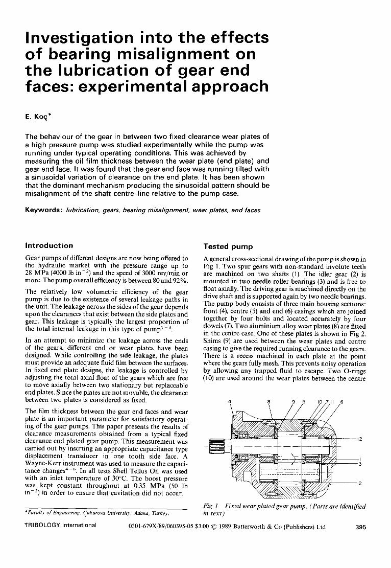
A general cross-sectional drawing of the pump is shown in Fig 1. Two spur gears with non-standard involute teeth are machined on two shafts (1). The idler gear (2) is mounted in two needle roller bearings (3) and is free to float axially. The driving gear is machined directly on the drive shaft and is supported again by two needle bearings. The pump body consists of three main housing sections: front (4), centre (5) and end (6) casings which are joined together by four bolts and located accurately by four dowels (7). Two aluminium alloy wear plates (8) are fitted in the centre case. One of these plates is shown in Fig 2. Shims (9) are used between the wear plates and centre casing to give the required running clearance to the gears. There is a recess machined in each plate at the point where the gears fully mesh. This prevents noisy operation by allowing any trapped fluid to escape. Two O-rings (10) are used around the wear plates between the centre
4 8 5 6 9 I0 711
I
Fig 1 in text)
Fixed wear plated gear pump. (Parts are identified
0301-679X/89/060395-05 $3.00 © 1989 Butterworth & Co (Publishers) Ltd 395

Koc - - effects of bearing misal ignment on gear end face lubrication
Fixed clearance end plate F~2
case and end covers to seal the fluid. Any possible leakage from the bearings to the underneath of the wear plates is prevented by O-rings and back-up rings (11). Two bush seals (12) located on each side of the driving shaft directly after the bearings are used to protect the oil seal from the high pressure developed by the pump.
These bush seals are loosely fitted inside the casing and are a close running fit on the shaft. The driven or idler shaft has a hole bored axially along the centre-line to ensure that no pressure difference exists between the two ends of the shaft. The two ends of the driven shaft are connected to the space between the bearings and bush seals of the drive shaft ensuring again that two ends of the drive shaft are identical hydraulically. Finally, the spaces beyond the bush seals on the drive shaft are both interconnected to two cavities between end plate and supporting casting. The cavity on the boost side of the unit is then connected back to the boost line by a hole through the wear plate. This pattern ensures that the direction of rotation can be changed simply by the reversal of the wear plate. It may be noted that this arrangement produces an end load on the drive shaft equal in magnitude to the shaft area times the boost pressure, which in fact, limits the maximum allowable boost pressure that can be used.
Modif icat ion to the pump
In order to measure the clearance, it was necessary to modify the existing pump to accommodate the transducer and connecting arrangements. Special attention was paid to the installation of the transducer in the gear tooth so that the cable could be taken out with minimum leakage.
The capacitive type displacement transducer 3'4 was inserted in one of the driven gear teeth. The transducer cable was taken out of the pump body through a hollow connecting tube (quill shaft) which was fitted inside the driven gear shaft. To prevent the pressure imbalance which might be caused due to this arrangement, the two end covers were initially drained to the tank. The initial tests with these arrangements showed that the running clearance obtained was excessively small under some operating conditions. Examination of the pressure dis- tribution showed that there was still a substantial pressure build-up at the end of the shaft and that there was a substantial end load acting on the gear shaft well in excess of manufacturing recommendations. Additionally the pressure distribution no longer corresponded to that in the original pump. It was therefore thought that these results would not represent the actual clearances occurr-
Floating bush seal Floating bush Quill shaft "~ \\ \
/ Adaptor Shaft extension
Fig 3 Pump modification
ing in the unmodified unit. Thus, it was decided to change the sealing arrangement in the pump to ensure an approximate pressure balance and to obtain pressures closer to those in practice.
Two bronze floating bush seals were made and used on both ends of the driven shaft and the spaces between two ends of the shaft and the bush seals were connected externally. These bush seals are loosely fitted in the end cover and one sits on the sealing surface of the quill shaft and the other sits on the similar diameter dummy shaft fitted on the other end of the driven shaft with close tolerances. These arrangements are shown in Fig 3.
To make room for the bush and the bolt holding the quill shaft in line, the drive side of the casing was drilled through and the space beyond the bush seal was drained to the tank. In a few tests, this end of the shaft was deliberately pressurized to examine the effect of end load on gear behaviour. In order to check that the balance has been achieved, two pressure tappings were drilled in between bush seals and shaft ends in the end covers and connected directly to the pressure gauges. Finally, a lip seal was used on the quill shaft to complete the sealing.
Clearance m e a s u r e m e n t results
A number of results were obtained with the initial modification made to the pump. However, the film thicknesses measured were exceptionally small and were felt not to represent the actual behaviour of the unit. Therefore, these results are not presented here. A substantial number of measurements of film thickness were made after the further modifications described above, and a representative selection is given here.
Interpretation
Figs 4-8 show the clearance variation over approxi- mately 1.5 shaft revolutions except for the lowest speed where only one pump revolution is displayed. Figs 9-14 are for larger numbers of revolutions so that the repeatability of the results from revolution to revolution could be examined. The vertical distance from the horizontal axis represents the film thickness in #m. The relatively large clearance zone in each plot marks the passage of the transducer over the silencing recess on the wear plate. The dotted lines in some plots represent the best sine curve fitted on those clearance curves.
The main feature of the clearance is the once per revolution, approximately sinusoidal variation of film
396 December 89 Vol 22 No 6

Ko~ - - effects o f bearing misa l ignment on gear end face lubr icat ion
E :L
o
o
7 0
0 . 0
/Silencing recess
Fig 4 Film thickness variation. 0.35 MPa boost pressure at 500 rev/min speed
70
E ::L
0.0
Fig 8 Film thickness variation. 7 MPa delivery pressure at 1000 rev/min speed
7 0
E :L
0.0
/ Silencing recess
Effect of cavitation
Fig 5 Film thickness variation. 0.35 MPa boost pressure at 1000 rev/min speed
E :L
,7 a
7O
0 . 0 ~
Effect of cavitation
Fig 6 Film thickness variation. 0.35 MPa boost pressure at 1500 rev/min speed
E
r~
c.)
701 eel"
Fig 7 Film thickness variation. 7 MPa delivery pressure at 1000 rev/min speed
E zk
c
7 0
0.o
Fig 9 Film thickness variation. 7 MPa delivery pressure at 1000 rev/min speed
thickness. The magnitude of the sinusoidal variation varies with operating conditions. However, the location of the maximum clearance remains the same in the middle of the high pressure region. Additionally, in some figures there is a second spike produced just after the minimum film thickness particularly under high speed conditions. It should be pointed out that this is not the true clearance but produced by the cavitation and consequent change in the dielectric constant of the fluid.
In order to attempt to find the cause of the sinusoidal variation a detailed metrological examination of the relevant parts of the pump was carried out. Four possible types of manufacturing inaccuracy could produce the sinusoidal clearance variation. These are:
(1) The gear teeth might be wedge shaped. (2) The gear end faces might be non-square relative to
the shaft centre line. (3) The centre case might be tapered. (4) The bearing centre-line might be misaligned relative
to the case.
Three of these can be examined relatively easily, the fourth is very difficult to assess with any accuracy.
The wedge-shape possibility was checked by measuring the lengths of the individual gear teeth. The variation in measurements is of the order of 5/ tm but does not show any systematic sinusoidal pattern. The overall non- squareness of the end face containing the transducer was investigated by placing the gear on two V-blocks at the points on the shaft corresponding to the bearing centres. The shaft was then supported at one end and was loaded gently against it. As it was rotated, the difference between two opposite pairs of teeth were measured. This was
TRI BO LOGY international 397
Ko~ - - effects of bearing misalignment on gear end face lubrication
E zk
8
(D
70
0.0
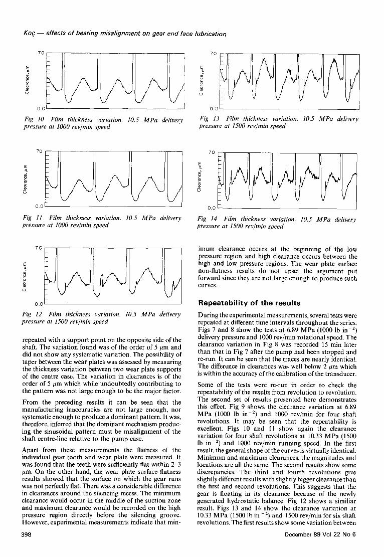
Fig 10 Film thickness variation. 10.5 MPa delivery pressure at 1000 rev/min speed
E
o
cD
7O
0.0
Fig 13 Film thickness variation. 10.5 MPa delivery pressure at 1500 rev/min speed
E :a.
g D ¢,D
7o
o.o
Fig 11 Film thickness pressure at 1000 rev/min
variation. 10.5 MPa delivery speed
7O
g
0.0
Fig 14 Film thickness variation. 10.5 MPa delivery pressure at 1500 rev/min speed
E ::k
o" =o
g m c.)
70
0.0
/ Fig 12 Film thickness variation. 10.5 MPa delivery pressure at 1500 rev/min speed
repeated with a support point on the opposite side of the shaft. The variation found was of the order of 5 #m and did not show any systematic variation. The possibility of taper between the wear plates was assessed by measuring the thickness variation between two wear plate supports of the centre case. The variation in clearances is of the order of 5 #m which while undoubtedly contributing to the pattern was not large enough to be the major factor.
From the preceding results it can be seen that the manufacturing inaccuracies are not large enough, nor systematic enough to produce a dominant pattern. It was, therefore, inferred that the dominant mechanism produc- ing the sinusoidal pattern must be misalignment of the shaft centre-line relative to the pump case.
Apart from these measurements the flatness of the individual gear tooth and wear plate were measured. It was found that the teeth were sufficiently fiat within 2-3 /~m. On the other hand, the wear plate surface flatness results showed that the surface on which the gear runs was not perfectly fiat. There was a considerable difference in clearances around the silencing recess. The minimum clearance would occur in the middle of the suction zone and maximum clearance would be recorded on the high pressure region directly before the silencing groove. However, experimental measurements indicate that min-
imum clearance occurs at the beginning of the low pressure region and high clearance occurs between the high and low pressure regions. The wear plate surface non-flatness results do not upset the argument put forward since they are not large enough to produce such curves.
Repeatability of the results
During the experimental measurements, several tests were repeated at different time intervals throughout the series. Figs 7 and 8 show the tests at 6.89 MPa (1000 lb in -2) delivery pressure and 1000 rev/min rotational speed. The clearance variation in Fig 8 was recorded 15 min later than that in Fig 7 after the pump had been stopped and re-run. It can be seen that the traces are nearly identical. The difference in clearances was well below 2/~m which is within the accuracy of the calibration of the transducer.
Some of the tests were re-run in order to check the repeatability of the results from revolution to revolution. The second set of results presented here demonstrates this effect. Fig 9 shows the clearance variation at 6.89 MPa (1000 lb in -E) and 1000 rev/min for four shaft revolutions. It may be seen that the repeatability is excellent. Figs 10 and 11 show again the clearance variation for four shaft revolutions at 10.33 MPa (1500 lb in -E) and 1000 rev/min running speed. In the first result, the general shape of the curves is virtually identical. Minimum and maximum clearances, the magnitudes and locations are all the same. The second results show some discrepancies. The third and fourth revolutions give slightly different results with slightly bigger clearance than the first and second revolutions. This suggests that the gear is floating in its clearance because of the newly generated hydrostatic balance. Fig 12 shows a similiar result. Figs 13 and 14 show the clearance variation at 10.33 MPa (1500 lb in -2) and 1500 rev/min for six shaft revolutions. The first results show some variation between
398 December 89 Vol 22 No 6

Koq - - effects of bearing misalignment on gear end face lubrication
different shaft revolutions. The second and fifth revolu- tions give larger clearances than the others as if the gear was oscillating in its end float. Fig 14 shows the clearance variation under the same operating test conditions on another day with the same effect as the pattern but to a smaller extent.
From all these results it may be revealed that the behaviour under the same operating conditions is reasonably repeatable. In addition, the repeatability of the unit, when it is stripped after a long period of time and between successive strips and rebuilds is excellent.
Effect of running condit ions
Speed effect
The most obvious effect of speed is on the minimum film thickness. Figs 4-6 show the clearance variation at zero delivery pressure (50 lb in -2 boost pressure) and 500, 1000 and 1500 rev/min running speed, respectively. It may be observed that the minimum clearance increases slightly with increased speed. It should be noted that these clearances represent the clearances under the transducer. These can be extrapolated by using the same sine curves to the tooth tips at which points the clearances of 3.5, 5.163 and 5.58/zm are found. There is obviously some uncertainity in the fitted sine curve and this is estimated to result in a minimum clearance error of about 1 #m at low speed and approximately 2 /~m at higher speeds. The shape of the curves given in these figures does not change greatly with speed. But at 1000 and 1500 rev/min running speed, there is a sharp apparent increase in clearance in the diverging region of the curves. This represents the cavitation occurring in the low pressure region where the clearance is diverging. In general, increasing speed increases the minimum film thickness and tilt.
Defivery pressure effect
The effect of delivery pressure on the behaviour of the gear was investigated by running the pump at different pressures. Figs 5 and 7 present the clearance variation under zero and 7 M P a delivery pressure at 1000 rev/min shaft speed, respectively. Comparing these curves it may be noted that there is significant elastic distortion around the silencing recess in the high pressure area with the plate being bulged-in at this point. However, apart from distortion at this region there is a general reduction in clearance with an increase in pressure.
Conclusions
From the experimental investigation into the general
behaviour of the gear under dynamic conditions, the following conclusions can be made:
(1) The main feature of each clearance curve is a once per revolution, approximately sinusoidal variation of clearance. The minimum film thickness always occurs in the low pressure zone, the maximum in the high pressure zone. This variation appears to be mainly due to a tilt of the gear relative to the wear plate.
(2) The clearance and tilt vary with operating conditions. Increasing the pressure decreases the minimum film thickness and increases the tilt. Increasing the pump speed appears to increase both the minimum film thickness and the tilt.
(3) At high speeds cavitation occurs in the low pressure zone where the clearance is diverging. This cavitation is represented in the clearance curves by a sharp apparent increase in clearance caused by the change in dielectric constant.
(4) At the higher pressures some elastic distortions, particularly around the silencing recess appear to be present, with the wear plate bending away from the gear.
(5) The results appear to be generally repeatable not only from revolution to revolution but also over longer periods.
Attempts to predict the behaviour of this design of wear plate on the basis of manufacturing inaccuracies, particu- larly a misalignment between the wear plates and the shaft centre-line, appear reasonably successful 6'7.
References 1. Henke, R.W. Internal leakage in gear pumps. Applied Hydraulics.
1955, 8, 63 66
2. Hooke, C.J. and Koe, E. End plate balance in gear pumps. Proc. Inst. Mech. Engrs., 1984, 198 B (2), 55-60
3. Ng, K., Koc, E. and Hooke, C.J. The lubrication of end plates in gear pumps-bush designs, Proc. 12th Leeds-Lyon Symposium on Tribology, Lyon. September 1985
4. Hooke C.J. and Kakoullis, Y.P. On-line measurement of film thickness, Proc. Conf. on Instruments and Computers for Cost- Effective Fluid Power Testing, Inst. Mech. Engrs, 1979
5. Koc, E. and Hooke, C.J. The lubrication and sealing of floating end plates in gear pumps. J. of National Con['. on Fluid Power, 1988, 1, 97-115
6. Koe, E. and Hooke, C.J. End lubrication and sealing in gear pumps with fixed end plates, J. of Fluid Control Including Fluitics Quarterly, May 1988, 18(3), 5249
7. Koe, E. End plate lubrication in external gear pumps, PhD Thesis, Mech. Eng. Dept., University of Birmingham, UK, 1983
TRI BOLOGY international 399
Precision Engineering is the foremost international journal devoted to the study of ultra-high precision engineering and metrology. It reports on the many techniques and disciplines vital to today's precision engineer, with a coverage ranging from nanotechnology to grinding, from sensors to materials science, from interferometry to elastic emission machining.
SUBJECTS COVERED INCLUDE
• Nanotechnology • Scanning tunnelling microscopy • Diamond turning • Precision bearings • Coordinate measurement machines • Precision grinding • Surface characterization • Sensors • Thermal effects
• Calibration and error compensation • Spindle error analysis • Measurement standards • Materials • Servo technology • Electro discharge machining • Elastic emission machining • Interferometry • Electro chemical machining
FEATURES • Refereed research papers • Technical notes • Conference reports • Book reviews • Calendar of forthcoming events • Industrial and product news
Published quarterly ISSN 0141-6359
For a sample copy or more information contact Geraldine Hills at Butterworth Scientific Ltd, PO Box 63, Westbury House, Bury Street, Guildford, Surrey GU2 5BH, UK. Tel: 0483 300966 Telex: 859556 SClTEC G Fax: 0483 301563
400 December 89 Vol 22 No 6