investigation into exposure when the visor of air fed … · investigation into exposure when the...
TRANSCRIPT

Prepared by the Health and Safety Laboratory for the Health and Safety Executive 2015
Health and Safety Executive
Investigation into exposure when the visor of air fed RPE is raised during spraying
RR1064Research Report


Mike Clayton BSc and Nick Baxter MScHealth and Safety LaboratoryHarpur HillBuxtonDerbyshire SK17 9JN
Air-fed visors (AFV) are commonly used within the Motor Vehicle Repair (MVR) trade for protection against exposure to isocyanate paints. However, a common practice amongst paint sprayers is to flip up the visor of their AFV immediately after spraying to check the quality of the paint finish. This may be only for a few seconds but if repeated numerous times during a work shift, this could potentially result in a significant increase in exposure. The aim of this project was to determine the reduction in protection and thus potential increase in exposure when the visor is lifted and to explore potential engineering solutions (by modifying the AFV design) to prevent exposure during any visor lift.
The results clearly demonstrate that lifting the visor whilst still within a contaminated atmosphere had a significant detrimental effect on the protection afforded by the AFV. Mean protection factors were measured at 1.7 in the lifted position and at 2.7 over the whole of the exposure period (from start of the lift to recovery of protection after refitting). This latter figure equates to a 15 fold increase in exposure when related to the assigned protection factor of40 for AFV when used correctly.
This report and the work it describes were funded by the Health and Safety Executive (HSE). Its contents, including any opinions and/or conclusions expressed, are those of the authors alone and do not necessarily reflect HSE policy.
Investigation into exposure when the visor of air fed RPE is raised during spraying
HSE Books
Health and Safety Executive

© Crown copyright 2015
First published 2015
You may reuse this information (not including logos) free of charge in any format or medium, under the terms of the Open Government Licence. To view the licence visit www.nationalarchives.gov.uk/doc/open-government-licence/, write to the Information Policy Team, The National Archives, Kew, London TW9 4DU, or email [email protected].
Some images and illustrations may not be owned by the Crown so cannot be reproduced without permission of the copyright owner. Enquiries should be sent to [email protected].
Acknowledgements
The authors would like to thank the external stakeholders within the motor vehicle repair trade who invited HSL researchers onto their sites. The authors would also like to thank David Fox, HSL, for conducting the interviews with the sprayers and the HSL volunteers who participated in this project.
ii

iii
KEY MESSAGES
Respiratory protective equipment (RPE) is extensively used to protect workers against
inhalation of chemical hazards. When correctly selected, maintained and used, RPE is capable
of providing effective control. However any deficiencies in the supporting programme that
underpins the management and deployment of RPE, or any poor workplace practices can reduce
the overall protection provided.
A common type of RPE used within the motor vehicle repair (MVR) trade for protection against
exposure to isocyanate paints is a supplied air device commonly referred to as an air-fed visor
(AFV). These devices are easy to don and doff and suit the types of activities undertaken by
paint sprayers. However a common poor workplace practice within the MVR trade is for
sprayers to flip up the visor of their AFV immediately after spraying to obtain a better view
when checking the quality of the paint finish. While the visor lift may be only for a few
seconds, this action, especially if repeated numerous times during a work shift, could potentially
result in a significant increase in exposure. The majority of sprayers interviewed during this
project stated they lifted their visor.
A series of tests have been undertaken to determine whether any degree of residual protection
remains when the visor is lifted and the implications of a visor lift on potential increase in
exposure. The findings of the tests, conducted using both a breathing simulator and test subjects,
show that the degree of residual protection provided by the visor when in the lifted position is in
the approximate range of 1 to 3.7 (mean 1.7) and the protection factor measured over the whole
of the exposure period (from start of the lift to recovery of protection after refitting) is in the
approximate range of 1.4 to 9.0 (mean 2.7). In terms of increase in exposure, this mean value of
2.7 equates to an approximate 15 fold increase in exposure when related to the assigned
protection factor of 40 for an air-fed visor when used correctly. Although only a sample range
of air-fed visors were tested, due to the fairly common design across this type of RPE, the
findings can be applied across all types of air-fed visors. In summary, the results of the tests
clearly demonstrate that lifting the visor whilst still within a contaminated atmosphere
significantly increases the wearer’s exposure.
It was found that when the visor is replaced after being lifted, it takes a period of time until the
protection provided by the RPE recovers to the level prior to the lift. This period of time was on
average about 15 seconds. In the terminology of the MVR industry this period of time could be
likened to the spray booth clearance time and could be referred to as the RPE clearance time.
Therefore it is important to note that increased wearer exposure is not just restricted to the lift
duration.
Additionally, a number of modifications were applied to the most common type of visor to
explore whether there is scope for improvement in design that would mitigate exposure during a
visor lift. Modifications that led to a significant improvement in protection were those that
maintained a clean breathing zone around the wearer’s mouth and nose. One was the addition of
a loose fitting inner mask positioned inside the visor that remained in place when the visor was
lifted. The second was a modification incorporating a window slit which removed the need to
lift the visor to obtain an unobstructed view of the workpiece, thus still maintaining a clean
breathing zone around the wearer’s mouth and nose.
Another common practice amongst sprayers was to apply masking tape over the edge of the
tear-off visors to prevent any over-spray from depositing on the main visor. This action
prevented sprayers from removing their tear-off visors whilst in the spray booth which may
have allowed improved vision and thus removing the need to lift the visor.

iv
EXECUTIVE SUMMARY
Study aim
The aim of the study was to determine the degree of potential exposure to an airborne
contaminant when the visor of an air-fed visor (AFV) is lifted and to explore potential
engineering solutions to reduce exposure during a visor lift.
The study had the following objectives:
Gather information relevant to visor lift by conducting informal interviews with paint
sprayers from the motor vehicle repair (MVR) trade.
Determine the reduction in protection and thus the potential increase in exposure as a
result of a visor lift by conducting a series of tests using a dummy head and a breathing
machine using a range of AFV.
Determine the reduction in protection and thus the potential increase in exposure as a
result of a visor lift by conducting a series of tests using volunteer test subjects using
two models of AFV.
Explore engineering solutions to enhance residual protection during a visor lift.
Develop an illustrative tool to demonstrate the effect of visor lift on protection provided
to the wearer.
Develop an exposure model for determining exposure or reduced protection given a
number of input variables including visor lift duration, visor lift frequency and wear
time.
Main findings
The findings of the tests conducted using both a breathing simulator and test subjects, show that
lifting the visor had a significant detrimental effect on the protection afforded by the AFV. The
degree of residual protection provided by the AFV when the visor is in the lifted position is in
the approximate range 1 to 3.7 (mean 1.7). The effect of the visor lift on the protection afforded
needs to also include the time taken to lift the visor away from the face to the lifted position, the
time the visor is in the lifted position, the time taken to refit the visor to the wearer’s face, and
the time taken for the protection to recover to its previous level. The protection factor measured
during this whole exposure period is in the approximate range 1.4 to 9.0 (mean 2.7).
Using the mean value taking the whole exposure period into account, the increase in exposure
during the period of the visor lift is approximately a factor of 15 when related to the assigned
protection factor (APF) of 40 for an AFV when used correctly. In the simulation spraying tests
carried out in this project the AFV typically returned protection factors >10,000 when worn and
used correctly. Relating the effect of the visor lift to a protection factor of 10,000 instead of the
APF of 40, equates to an increase in exposure during the period of the visor lift of
approximately a factor of 3700.
To put this increase into context, it has to be related to the total daily AFV wear time based on a
typical number of spraying sessions per day. The majority of sprayers interviewed stated they

v
lifted the visor at least once during each spraying session, and therefore assuming a lift time of 5
seconds, the potential increase in exposure based on the APF of 40 is a factor of 1.2, and on a
protection factor of 10,000 is a factor of 52.
Although only a sample range of air-fed visors were tested, due to the fairly common design
across this type of RPE, the findings can be applied across all types of air-fed visors. In
summary, the results of the tests clearly demonstrate that lifting the visor whilst still within a
contaminated atmosphere significantly increases the wearer’s exposure.
It was found that on refitting the visor after a lift, the protection to the wearer took
approximately 15 seconds to return to 80% of the level before the visor lift. We have referred to
this as the RPE clearance time. The mean RPE clearance time was found to be approximately
15 seconds for Model A (the most common model used in the MVR trade and in which the air
inlet is built into the chin area of the visor) and 16 seconds for Model F (which has the air flow
inlet in the head-top providing an air flow down across the wearer’s face), and this value did not
vary with lift duration. The RPE clearance time should be added to the lift duration time to give
a total exposure time to the wearer.
A number of modifications were applied to the most common type of visor to explore whether
there is scope for improvement in design that would mitigate exposure during a visor lift.
Modifications that maintained a clean breathing zone around the wearer’s mouth and nose led to
a significant improvement in protection. This was achieved with the addition of a loose fitting
inner-mask positioned inside the visor that remained in place during the lifting of the visor. If
adequate protection can be achieved with a loose fitting mask then the discomfort issues
associated with a tight fitting mask will not occur. Another modification explored was to create
a slit in the visor to enable an unrestricted view while keeping the main body of the visor and air
inlet in place. This window slit configuration also maintained a clean breathing zone around the
wearer’s mouth and nose. Other modifications explored repositioning of the air distribution
system inside the visor, an air curtain blowing across the breathing zone and variation in air
flow rates into the visor.
Another common practice amongst sprayers was to apply masking tape over the edge of the
tear-off visors to prevent any over-spray from depositing on the main visor. This action
prevented sprayers from removing their tear-off visors whilst in the spray booth which may
have allowed improved vision and thus removed the need to lift the visor.
Additional findings from the site visits
Whilst all sites visited had an acceptable level of record keeping in relation to servicing and
testing of the spray booth and breathable air compressors, the record keeping covering the
maintenance of the AFV was generally poor or non-existent. It was common for the AFV to be
personally issued and the sprayers responsible for their maintenance. Although heavily
contaminated with paint the AFV in use at the time of the visits were generally in a reasonable
condition and when used correctly should be capable of providing adequate protection. There
was no structured RPE training for wearers; instead firms relied on the sprayer’s ability to pick
up correct use and/or their prior employment experience.

vi
CONTENTS PAGE
1 INTRODUCTION .................................................................... 1
1.1 Background 1
1.2 Effect of a visor lift 1
1.3 Study aim 2
2 IMPLICATIONS ...................................................................... 4
3 MOTOR VEHICLE REPAIR BODYSHOP SITE VISITS ......... 5
3.1 Objectives of the site visits 5
3.2 Setting up and carrying out the interviews and observations 5
4 AIR-FED VISOR TYPES INVESTIGATED ............................. 6
4.1 Models selected for the study 6
4.2 Designs of air-fed visors 6
4.3 Air flow measurements 10
5 METHODOLOGY ................................................................. 11
5.1 Dummy head non-breathing 11
5.2 Dummy head and breathing machine tests 11
5.3 Simulated spraying tests using human subject tests 12
5.4 Visor improvement 14
6 MOTOR VEHICLE REPAIR BODYSHOP SITE VISITS ....... 19
6.1 General 19
6.2 Summary of main findings 19
6.3 Implications for main study 21
7 TEST RESULTS................................................................... 22
7.1 Terms and definitions 22
7.2 Dummy head non-breathing 23
7.3 Dummy head and breathing machine tests 24
7.4 Simulated spraying tests using human subjects 25
7.5 Visor improvement tests 25
8 DISCUSSION AND CONCLUSION ...................................... 28
8.1 Dummy head non-breathing 28
8.2 Dummy head and breathing machine tests 28
8.3 Simulated spraying tests using human subjects 29
8.4 Visor improvement tests 29
8.5 Illustrative visor lift video tool 31
9 REFERENCES ..................................................................... 33
APPENDIX A- MOTOR VEHICLE SITES VISIT REPORT ............ 34

vii
APPENDIX B – BREATHING MACHINE DATA ........................... 38
APPENDIX C – SIMULATED SPRAYING TEST DATA ................ 39

1
1 INTRODUCTION
1.1 BACKGROUND
HSE guidance on the control of exposure to isocyanate paint spray (HSE 2014) promotes best
practice for the selection and use of respiratory protective equipment (RPE), recommending that
air-fed half face mask breathing apparatus or air-fed visors (AFV) be used. For reasons of
comfort and wearer acceptability – ease of use, and greater field of view - AFV are the most
common RPE choice. Isocyanates are recognised as a cause of occupational asthma (HSE,
2010). Spray painters using isocyanate-based paints in the motor vehicle repair (MVR) trade are
a group at risk of exposure.
Previous laboratory and workplace studies carried out by HSL (Bolsover, 1996, 2006; Vaughan
and Rajan-Sithamparanadarajah, 2005) concluded that AFVs are capable of providing adequate
levels of protection when correctly used and maintained. Vaughan and Rajan-
Sithamparanadarajah in their application of a data treatment method to the workplace data set on
air-fed visors (Bolsover et al, 2006), concluded that a fifth percentile protection factor value of
312 could be drawn from the data.
Therefore taken at face value, AFV should provide an adequate degree of protection when
correctly used, however poor workplace practices can have a negative effect on the protection
provided. One such negative practice is for sprayers to lift or flip up the visor of their AFV
immediately after spraying to check the quality of the paint finish. This is done because there is
only a short period of time (up to about 20 seconds) while the paint film is ‘wet’ and further
paint can be applied if necessary without compromising the finish (Sanders and Davies, 2006;
Jones et al, 2012). Sprayers lift up the visor to obtain a better view of the paint finish than that
when seen through the visor of their AFV. The short period of time while the paint film is ‘wet’
is not sufficient time for the LEV inside a spray booth to reduce the isocyanate concentration in
the ambient atmosphere to safe levels. While the visor lift may be only for a few seconds, this
action, if repeated numerous times during a work shift, can significantly increase AFV user
exposure.
1.2 EFFECT OF A VISOR LIFT
RPE when selected, worn and maintained correctly is assumed to provide protection at or
greater than their assigned protection factor (APF). Therefore when an AFV is used correctly
within an effective RPE programme, it is assumed that the protection provided to the wearer
over their shift will be at least a protection factor of 40 (BSI 2005a). In terms of exposure, using
RPE with an APF of 40 should result in a wearer’s potential exposure being reduced by at least
a factor of 40. AFV are loose-fitting RPE, i.e. they fit loosely to the wearers face and rely on a
sufficient air flow through the device to maintain protection, therefore, if the visor is lifted
whilst the wearer is still inside a spray booth and before the booth clearance time has elapsed,
the wearer is likely to be exposed to any residual airborne paint spray.
Unless there is any residual protection provided by the AFV when the visor is lifted, the period
of visor lift can be treated as a period of non-wear. The effect of just a small period of non-wear
can greatly reduce the protection afforded. During the non-wear time the protection factor
effectively falls to one (i.e. no protection) and this leads to a significant reduction in the overall
protection provided as can be seen from the graph in Figure 1.

2
Figure 1 Effect of non-wear time on Protection Factor. The solid line represents a starting protection factor of 40. The dashed line represents a starting protection factor
of 312
For example, if the visor is lifted 5 times for 10 seconds for every 15 minutes of wear during
spraying, that is equivalent to a non-wear time of 5.6% (50 / (15*60) * 100). This has the result
of reducing the protection factor from 40 (based on the APF for an AFV complying with the
requirements of BSEN14594:2005 (BSI 2005b) and shown as the solid line in Figure 1) to a
protection factor of 13. This is a significant reduction in protection, which in terms of increased
exposure is equivalent to approximately a three-fold increase in exposure. Since 95% of wearers
should be achieving protection factors >40, if we apply the non-wear time calculation to a PF in
use of 312 (Vaughan and Rajan-Sithamparanadarajah 2005; shown as the dashed line in Figure
1), a 5.6% non-wear time would result in reducing the protection factor to 17 which is a 18 fold
increase in exposure when compared to that being achieved when worn correctly. However, this
effect on protection is based on the worst case assumption that when the visor is lifted the
protection factor is equal to 1, which may not be the case if there is some residual protection
provided by the AFV even when the visor is in the lifted position.
1.3 STUDY AIM
The aim of the study was to determine the degree of potential exposure to an airborne
contaminant when the visor of an AFV is lifted and to explore potential engineering solutions to
reduce exposure during a visor lift.
The study has the following objectives:
Gather information relevant to visor lift by conducting informal interviews with paint
sprayers from the MVR trade.
Determine the reduction in protection and thus the potential increase in exposure as a
result of a visor lift by conducting a series of tests using a dummy head and a breathing
machine using a range of AFV.

3
Determine the reduction in protection and thus the potential increase in exposure as a
result of a visor lift by conducting a series of tests using volunteer test subjects using
two models of AFV.
Explore engineering solutions to enhance residual protection during a visor lift.
Develop an illustrative tool to demonstrate the effect of visor lift on protection provided
to the wearer.
Develop an exposure model for determining exposure or reduced protection given a
number of input variables including visor lift duration, visor lift frequency and wear
time.

4
2 IMPLICATIONS
This report describes the work undertaken to understand the effect on exposure of a wearer
lifting the visor of their AFV whilst still within a contaminated area, and to explore whether the
effect of exposure can be mitigated by the application of simple engineering modifications to
the AFV.
When used correctly, AFV can provide adequate protection preventing inhalation of isocyanates
as shown from previous workplace and laboratory studies and also from tests conducted in this
project using a harmless test aerosol. However, the lifting of the visor whilst still in a
contaminated area can place the wearer at risk of exposure to isocyanates.
One of the questions which is addressed by this project is to understand whether there remains
any residual protection offered by the AFV when the visor is in the lifted position. Does the
period during which the visor is lifted equate to a period of non-wear in which it is assumed that
the protection offered by the RPE is zero, i.e. a protection factor of 1?
The finding of the exposure tests using a dummy head shows that the residual protection offered
by the range of visor types tested when the visor of the AFV is in the lifted position is between
1 and 2.2. The visor designs which have the air flow inlet in the head-top providing an air flow
down across the wearer’s face returned residual protection factors slightly higher than those
designs where the air inlet is built into the chin area of the visor and is lifted away from the face
when the visor is raised. The latter design types are the most common models used in the MVR
trade.
During the visor lift the protection factor doesn’t instantaneously fall to the residual protection
factor, nor on replacement does it instantaneously return to the protection factor measured
immediately prior to the lift, and therefore the effect of the lift on the protection factor and thus
exposure is different to the residual protection factor. The protection factors measured during
the whole of the exposure period ranged from 1.4 to 9.0 (mean 2.7).
Testing has demonstrated that potential modification to the general AFV design can improve the
protection offered to the wearer during a simulated visor lift. A significant improvement in
protection is achieved when a clean air supply is maintained around the breathing zone of the
wearer. Within this project, an inner mask and a window slit configuration successfully
achieved this. However, in these configurations the wearer is still exposed to considerably more
contamination compared with when the AFV is used correctly.

5
3 MOTOR VEHICLE REPAIR BODYSHOP SITE VISITS
3.1 OBJECTIVES OF THE SITE VISITS
The purpose of the site visits was to gather information to inform the parameters to employ in
the laboratory exposure testing. There were three main objectives for the site visits:
i) To hold informal interviews with paint sprayers to gain a better understanding of the
frequency and duration of a visor-lift and duration and frequency of wear;
ii) To observe paint sprayers in order to understand the movements and work rates
involved; and
iii) To record the range of air-fed visors in use.
Additionally, the visits were seen as an opportunity to ask the paint sprayers about the problems
they experience when using their air-fed visor.
3.2 SETTING UP AND CARRYING OUT THE INTERVIEWS AND OBSERVATIONS
Semi-structured interviews were the preferred methodology for engaging with the paint
sprayers. The primary focus of the interviews was to elicit information from paint sprayers on
the practice of visor lifting, in the spray booth, during a painting session. However, as this visor
lifting behaviour contravenes good practice, and probably the employer’s health and safety
requirements, the research team concluded that the interviews would need to be conducted with
a degree of sensitivity in order to elicit honest responses from interviewees.
Given these sensitivities, the research team decided that:
The interviews would be conducted on a one-to-one basis, in a private room at the
sprayers place of employment;
Responses would be captured using written notes rather than audio recording; and
All interviewees would be asked the same questions, guided by a common question set.
A question set was developed (see Appendix A), and piloted on a paint sprayer working locally
to HSL. A number of minor changes were subsequently made as a result of the pilot.
All interviews were conducted in a private room, free from distractions. Written notes were
taken during each interview, and subsequently aggregated and analysed to produce an overall
impression of the practices and opinions of the paint sprayers. The paint sprayers were also
asked to make a subjective judgement of the perceived exertion required during paint spraying –
this was based on the Borg Scale of Exertion (Borg, 1982) – see Appendix A.
A second researcher from the HSL PPE Team visually examined the AFV in use at the sites and
engaged with management to discuss the RPE programme arrangements.
The findings of the site visits and interviews are reported in section 6.

6
4 AIR-FED VISOR TYPES INVESTIGATED
4.1 MODELS SELECTED FOR THE STUDY
From information provided by HSE, Ford Retail paint shop, the Vehicle Builders and Repairers
Association (VBRA) and from the information gained during the site visits the following
models were identified for the study:
Table 1 Air-fed visor models, types of face seal and associated APF
When tested for CE certification AFV must not exceed the maximum permitted level of inward
leakage at the manufacturer’s minimum design condition which can be either a minimum stated
pressure or air flow rate. For BSEN14594, (BSI 2005), Class 3A/3B devices and BSEN270
(BSI 2000) devices, the maximum inward leakage is 0.5%, (Nominal Protection Factor of 200),
and for BSEN14594 Class 4A/4B devices, the maximum inward leakage is 0.05%, (Nominal
Protection Factor of 2000). Model A was initially HSE approved to TM14/7.25 (HSE 1990) and
was required not to exceed the maximum permitted level of inward leakage of 0.5%, (Nominal
Protection Factor of 200).
Class A devices have less stringent mechanical strength requirements than class B devices.
4.2 DESIGNS OF AIR-FED VISORS
Air-fed visors generally follow the same basic design of a visor worn on the head with a
moveable full face shield with either an elasticated non-woven fabric type or closed-cell foam
type face seal that closes the gap between the wearer’s face and the edge of the visor.
Compressed air at a flow rate between 200 and 300 l/min (typically) and approximately 4 – 7
bar supply pressure (typically) is provided to the facepiece via a belt mounted air flow rate
control valve to provide protection against ingress of contamination. The belt mounted air flow
rate control valve regulates the air flow to a more or less constant flow rate over the range of
supply pressures. Where various manufacturers’ models differ in design is whether there is user
adjustment provided on the belt mounted air flow rate control valve and the design of air inlet
inside the visor. A typical design of an AFV can be seen in Figure 2.
AFV Model Type of face seal employed
Flow control valve
Certification APF
Model A Fabric N PPE Directive 89/686/EEC
40
Model B Foam N PPE Directive 89/686/EEC
40
Model C Fabric N BSEN14594 Class 4A
40
Model D Foam N BSEN14594 Class 4A
40
Model E Foam Y BSEN270 40
Model F Fabric Y BSEN14594 Class 3B
40
Model G Fabric Y BSEN14594 Class 3B
40

7
Figure 2 Typical design of an air-fed visor
Three models were fitted with user air flow adjustment. For Models A, B, C, D and E, the air
inlet inside the visor terminated in the chin area of the visor. Towards the end of the tube there
is a series of holes through which the air is directed into the visor. A foam sleeve which acts as
both an air diffuser and silencer is placed over the holes. See Figure 3.

8
Figure 3 Air inlet tube in Model A
In these models the air inlet is fixed to the lower part of the visor so that when this visor is lifted
away from the face the air inlet is also moved away from the wearer’s breathing zone. See
Figure 4.
When lifted, most of the air-fed visor’s visor moves to a position approx. 90o to the wearer’s
face. The visor on Model E lifts a little further than the others to approximately 110o relative to
the wearer’s face.
Figure 4 Photographs showing Model A and Model F air-fed visor in the lifted position
Ball probe sampling
at mouth of dummy
head
Foam inlet tube diffuser

9
Model F and G, which originated from a design of powered respirator and therefore share a
common head-top, employ a much larger air path to the visor. Both these designs comprise a
large bore breathing hose which routes the compressed air from the belt mounted air flow rate
control valve to the breathing zone over the top of the hood and down across the face of the
wearer. Therefore when the visor is lifted the air inlet remains in its original as worn position,
however the air path is obstructed to a varying degree by the fabric face seal of the visor when it
is in the lifted position. See Figure 5.
Figure 5 Model F air-fed visor showing the air inlet position
Air inlet

10
4.3 AIR FLOW MEASUREMENTS
The air flow rate into the air-fed visor over the range of manufacturers’ specified pressures was
measured. Where a belt mounted wearer-operated air flow rate control valve was fitted,
minimum and maximum flow rates were measured at the extreme of the flow adjustor settings.
The range of air flow rates used during the exposure tests ranged from 193 l/min to 325 l/min.
The flow rate for most devices that did not have a wearer-operated flow adjustor did not alter
significantly (typically < 200 l/min) over their specified input pressure range. The greatest
variation in air flow rate was obtained for devices that had a wearer-operated air flow adjustor,
with Model E having the largest range from 193 l/min to 325 l/min.

11
5 METHODOLOGY
A series of Inward Leakage (IL) tests using a salt aerosol challenge were carried out to
determine the protection offered by AFV devices during correct use and while in the lifted
position. The salt aerosol challenge concentration was approximately 10 + 2 mg/m3. This is
based on standard RPE test requirements (BSI 2001). The tests were carried out inside the PPE
IL chamber using a combination of dummy head non-breathing, dummy head with breathing
simulator and human subjects.
The downward air flow rate within the PPE IL chamber is approximately 0.4 m/s. This flow rate
is similar to the downward air velocity within a typical downdraught spray booth.
5.1 DUMMY HEAD NON-BREATHING
The AFV was fitted to the dummy head with the visor in the lifted position. Once the IL
chamber was filled with the required challenge aerosol concentration, the concentration at the
mouth of the dummy head was measured without the AFV operating. This is equivalent to a
situation of full exposure to the chamber challenge concentration. The AFV supply pressure and
flow settings were then adjusted as required and the challenge concentration at the mouth of the
dummy head measured. By comparing the ratio of the two measurements to the challenge
aerosol concentration the reduction in potential exposure provided by any residual protection
afforded by the air-fed visor in the lifted position can be determined.
The results are shown in Section 7.2.
5.2 DUMMY HEAD AND BREATHING MACHINE TESTS
The AFV was fitted to the dummy head with the visor in the down position and the air supply
pressure and flow settings were then adjusted as required. Once the IL chamber was filled with
the required challenge aerosol concentration, the challenge concentration outside the AFV and
the concentration at the mouth of the dummy head were measured – this gave a baseline
measurement. The visor was then lifted for the predetermined durations and an exposure
measurement was taken throughout the visor lift period and until the contaminant concentration
inside the visor returned to the within 80% of the baseline value.
The tests were conducted at breathing rates of 30 l/min and 40 l/min. There is no report of a
study in which the work rate of sprayers has been measured however, from the interviews with
sprayers most considered the work to be ‘light’ to ‘somewhat hard’ on the Borg scale.
According to BS 4275 (BSI 1997), (now superseded by BS EN 529 (BSI 2005a) - but the latter
does not contain work rate information), ‘light manual work’ is considered ‘low’ and with an
associated peak inhalation flow rate of up to 100 l/min which is equivalent to a sinusoidal
breathing rate of 30 l/min; and ‘sustained hand and arm work’ is considered ‘moderate’ and
with an associated peak inhalation flow rate of up to 150 l/min which is equivalent to a
sinusoidal breathing rate of approximately 40 l/min.
The visor can be lifted at any point in time throughout the breathing cycle. The data from the
scoping study showed that when the visor was lifted at the start of the inhalation phase, the
measured exposure was generally a little higher than when lifted at the start of the exhalation

12
phase. This was not unexpected as lifting the visor on inhalation will result in more complete
inhalations whilst the dummy head (‘wearer’) was exposed to the challenge concentration. For
the additional tests conducted, the lift was synchronised with the start of the inhalation phase.
The results are shown in Appendix B.
5.3 SIMULATED SPRAYING TESTS USING HUMAN SUBJECT TESTS
5.3.1 Purpose
To obtain a more realistic measurement of the effect a visor lift has on the protection provided
by the AFV, a series of exposure tests was carried out on human test subjects wearing an AFV
whilst inside the IL chamber using sodium chloride as the exposure challenge. The purpose of
running a series of tests on human test subjects was to determine the effect of the visor lift on
the protection offered to the wearer and therefore their potential exposure.
The results are shown in Appendix C.
5.3.2 Ethical approval
Project specific ethical approval was required for the human subject testing as the test protocol
required volunteers to deliberately lift up the visor of the AFV that they would be wearing
whilst inside the test chamber containing a test challenge agent of sodium chloride aerosol.
Ethical approval was obtained (ETHCOM/REG/13/04) and five volunteer test subjects were
recruited to participate in the study from the HSL PPE volunteer pool. The test subjects are
identified in this report as subject 1 through 5. The volunteers were assessed as medically fit to
take part in this study by HSL’s Centre for Workplace Health Unit. During testing each
volunteer had their heart rate monitored for the duration of the tests as a precaution against over-
exertion. A withdrawal criterion of the subjects’ maximum heart rate (185-age x 0.65) was used;
no subject had to be withdrawn.
5.3.3 Visor types employed in the human subject tests
The human subject tests were performed using Model A and Model F. Model A was selected as
this is the most commonly used model within the industry and is an example of the most
common air inlet position (in the area of the chin). Model F was selected as it was an example
of a device with the air inlet positioned at the forehead and from the knowledge gained from the
scoping study and from the dummy head/breathing machine tests Model F showed the highest
residual protection. This testing would give a comparison of the two different air inlet positions.
Five volunteer test subjects were tested inside the PPE IL chamber while wearing the selected
AFV models, a total of three times for each device. Whilst inside the IL chamber, the test
subjects carried out a walking exercise, two simulated spraying activities and a series of
simulated visor lifting activities.

13
5.3.4 Simulated spraying activity
From the data on work rate and from observations of spraying activities gained from the site
visits, two simulated spraying activities were designed:
Simulated spraying whilst standing, with sweeping arm movements at between chest
and head height (Figure 6a).
Simulated spraying whilst in a kneeling position with head lowered simulating spraying
a sill or wheel arch of a motor vehicle with head movement looking over shoulder to
both the right and left hand side (Figure 6b).
Figures 6a & 6b Examples of similar positions adopted during actual spraying (Figure 6b reproduced from Bolsover et al 2005)
5.3.5 Visor lift period
From the data gathered from the site visits the following visor lift periods were selected for use:
5, 10, 15, 20 and 25 seconds. The sprayers’ responses (n=20) to the question on the period of
visor lift ranged from 2 seconds to 30 seconds. Most responses on the maximum lift period were
10 seconds with just one of 30 seconds. It was decided not to use 2 seconds as this lift period
does not permit time for any degree of inspection and also it would be difficult measuring the
impact of a visor lift in this short duration. It was also decided not to use and 30 seconds as this
was only from a single response.
5.3.6 Simulated visor lift Following a measurement of the protection provided by the AFV during the two simulated
spraying activities, the volunteer was asked to stand breathing normally and then while holding
their breath, lift up the visor to simulate inspection of the sprayed item (Figure 7). After 5, 10,
15, 20 or 25 seconds, the volunteer replaced the visor to the normal position and breathed
normally for a further 60 seconds. Sampling continued before, throughout and after the visor lift

14
period thus providing a continuous measure of the protection factor. Before commencing the
next visor lift duration, the volunteer was asked to carry out approximately ten head up and
down movements and ten head side-to-side movements. The protection offered by the device
was not measured during these movements, the sole aim of which was to return the AFV and
more importantly the fabric face seal into its naturally resting position after the previous
simulated lift. This was repeated until all the visor lift durations had been completed.
Figure 7 Example of visor lift following spraying
(Photograph taken during simulated spraying)
5.4 VISOR IMPROVEMENT
The purpose of the visor improvement testing was to explore possible engineering solutions to
increase the residual protection offered by an AFV while in the lifted position. The concepts to
be investigated were:
Increased air flow.
Chin and forehead air inlet positions.
With and without the fabric face seal.
Slit in visor window.
Without visor screen.
Having an inner mask which stays in place when the visor is lifted.
Incorporating an air curtain as the inlet flow.
For all the AFV improvement tests, the modified AFV was fitted to the dummy head and the IL
chamber was filled to the required challenge aerosol concentration. The AFV was orientated and
operated on the breathing machine as described in the sections 5.4.1 to 5.4.6. The concentration
at the mouth of the dummy head was measured and gave the residual protection offered by the
AFV in the described orientation.

15
5.4.1 Increased air flow
With the AFV fitted to the dummy head and not connected to the breathing machine, and with
the visor in the lifted position, the supply pressure was regulated between the minimum and
maximum manufacturers operating pressures. To maximise the air flows, the belt mounted air
flow rate control valves were operated on the minimum and maximum settings. Model F and
Model E were used as they gave the greatest variation in air flows controlled by the belt
mounted air flow rate control valves. The maximum air flow was 325 l/min given by Model E.
To investigate the effect on higher flowrates, the head-top from Model F was connected to an
external blower unit and tested with flowrates of 200 – 500 l/min while fitted to a dummy head
with the breathing machine operating at 30 l/min.
5.4.2 Air inlet positions
Model A was fitted to the dummy head, not connected to the breathing machine and tested with
the air inlet located in the chin position (as originally supplied) and positioned across the
forehead (attached to the forehead cradle strap), see Figure 8. The tests were performed with
and without the fabric face seal in place. Model F was fitted to the dummy head and not
connected to the breathing machine.
Figure 8 Air inlet on forehead with and without fabric face seal
5.4.3 Slit in visor window
A slit (approximately 145 x 50 mm) was cut from the front of Model A, located in front of the
eyes of the dummy head (Figure 9). The theory behind this idea was instead of lifting the whole
visor up, a small section of the visor could be opened which would still leave a considerable
portion of the visor in place to contain the air supply around the wearer’s breathing zone. It may
be possible to manufacture a window into the visor to allow this operation. The mechanics of
how the window could be manufactured was not investigated here, but simply the residual
protection offered by the AFV with the window slit open was investigated. This idea is based on
a product supplied to the German market by the manufacturer of Model E. It is not known how
widely this product is used.
Foam diffuser
over air inlet

16
Model A with the window slit in the visor was fitted to the dummy head and tested with and
without the breathing machine operating. The air inlet positions were varied between the chin
and forehead positions, and the supply pressure varied between minimum and maximum
manufacturer’s operating pressures.
Figure 9 Window slit with air inlet at chin
5.4.4 Without a visor screen
Model A was tested with the visor screen removed (Figure 10). This is similar to the window
slit but instead of lifting a small section of the visor, the entire visor screen could be lifted
leaving the frame work of the AFV and fabric face seal in place along with the air inlet. A good
analogy would be the visor on an open-faced motorcycle crash helmet. This would keep the air
inlet in position when the visor is lifted. The mechanics of how the visor screen could be lifted
alone was not investigated here, but simply the residual protection offered by the AFV with the
visor screen removed (to represent the screen in the lifted position) was investigated.
Model A with the visor screen removed was fitted to the dummy head and tested with and
without the breathing machine operating. The air inlet positions were varied between the chin
and forehead positions, and the supply pressure varied between minimum and maximum
manufacturer’s operating pressures.

17
Figure 10 AFV without visor screen
5.4.5 AFV incorporating an inner mask
The theory behind this idea was to have a loose fitting inner mask that remained in position
when the visor was lifted, therefore maintaining an enclosed area of breathable air around the
wearer’s breathing zone. Three different designs of inner mask were tested using Model A. One
was a simple loose fitting mask with two holes, one on either side, around the nasal area. This
inner mask design was chosen as the two holes provided a means for the air flow to exit the
inner mask. This was tested with and without the holes taped up, and with the mask edges taped
to the dummy head (to represent a tight fitting inner mask). The second type of inner mask was
a simple loose fitting mask with check valves. This was chosen as the check valves would limit
any contamination being drawn into inner mask during the inhalation cycle. The third type of
inner mask was identical to the first with the nasal holes taped up, but with larger bore supply
tubing so that higher flowrates could be achieved. The three designs of inner mask are shown in
Figure 11.
Model A incorporating an inner mask was fitted to the dummy head and tested with and without
the breathing machine operating. The set up was tested with different air flowrates into the inner
mask. With all three inner mask designs, the visor could be lowered, not completely, but to such
an extent that the fabric face seal could be located underneath the chin of the dummy head.

18
Figure 11 From left to right, inner mask 1, inner mask 2 and inner mask 3
5.4.6 Air curtain flow pattern
The idea was to adapt the air inlet to provide a curtain of air across the wearer’s breathing zone
instead of the standard air inlet which distributes the air in all directions. A different air supply
tubing was used inside Model A, with a slit cut along the length below the breathing zone. To
direct the air flow towards the breathing zone of the dummy head, a portion of the slit was taped
up. See Figure 12. This set up was tested with and without the foam diffuser and at the
manufacturer’s maximum and minimum operating pressures. Model A with the window slit and
no visor configurations were tested with the air curtain flow pattern. Each set up was fitted to
the dummy head and tested with the breathing machine operating.
Figure 12 Air curtain configuration without foam diffuser
Slit cut into
breathing tube

19
6 MOTOR VEHICLE REPAIR BODYSHOP SITE VISITS
6.1 GENERAL
Six body shops were visited, ranging from a major vehicle manufacturing company to a small
family run firm. A total of 20 interviews were carried out by a human factors specialist.
Paint spraying was being conducted at four sites at the time of the visit, which permitted
observation by a second researcher. A further site set up a test piece so that spraying could be
observed. The spraying activities witnessed tended to be small pieces of work that required
short, but repeated spray coats. The paint sprayers were also asked to make a subjective
judgement of the perceived exertion required during paint spraying.
A summary of the main findings is given below with more detailed site specific information
given in Appendix A.
6.2 SUMMARY OF MAIN FINDINGS
In most cases, it was felt that the sprayers were honest and open and provided useful
information.
At one site, the sprayers were reticent and it was felt that they had been briefed by
management prior to the visit.
A majority of the sprayers (14/20) stated they lifted their visor during a period of spraying,
and before the booth had cleared, however no visor lifts were witnessed during the periods
of observation.
One sprayer was observed to remove their AFV whilst in the spray booth within one minute
after cessation of spraying and well before the required booth clearance time.
The period of visor lift ranged from 2 – 30 seconds, with a period of about 5 seconds
reported as typical.
Common reasons given for a visor lift were:
o Poor visual clarity of the visor;
o Over spray and a scratched visor;
o Working low down on a vehicle where the light is not as bright;
o Reflections due to lighting and booth wall construction; and
o Working with white and silver paints.
The typical number of times an AFV was worn during a shift ranged from 2 to 28, with
most of those who stated they lifted their visor saying that they would lift on average once
in each period of wear.

20
One site had purchased and put into use new air-fed visors just a couple of days prior to the
visit.
Generally, the site management (owner or body shop manager) were happy to talk about
their RPE programme, but the sprayers tended to only allow a quick look at their RPE.
In all cases the RPE was issued on an individual basis with the sprayers responsible for
maintaining their own kit. There was little evidence that the in-line filters in the air-fed
visors were being changed regularly.
Although most of the RPE seen were heavily used (apart from the site that had purchased
new RPE), it was generally in a condition that would provide a degree of protection. Faults
were found on four AFVs and these were brought to the attention of the management.
Generally, record keeping covering maintenance of RPE was poor or non-existent; however,
the major vehicle manufacturing sites did have reasonable record keeping.
All sites had regular spray booth clearance time checks and notices were posted on all spray
booths seen.
In a number of spray booths, the compressed air regulator and gauge were caked with paint
making it impossible to check the breathing air outlet pressure. No sprayer said that they
knew what the outlet pressure for the air-fed visor should be or checked it regularly. They
tended to assume the regular breathable quality checks (which in all cases were provided by
an external contractor) would ensure that the pressure and flows were set correctly.
One sprayer mentioned that the low flow warning whistle operated on occasions but he
didn’t know that this indicated a reduction in air flow rate to the visor.
Use of masking tape to seal the edges of the tear off visors, with the aim to keep the main
visor clean, was a common practice. This prevented wearers removing a splattered tear-off
visor during spraying.
Generally, there was a lack of training; instead, sprayers rely upon common sense and prior
employment experience.
Many sprayers had facial hair.
The perceived exertion during spraying ranged from ‘no exertion at all’ to ‘it is hard and
tiring but continuing is not terribly difficult’, but most perceived the exertion was in the
‘light’ to ‘somewhat hard’ range on the Borg scale.
Each time a sprayer exited the spray booth they disconnected the AFV from the air supply.
It was noted that this disconnection was not always at the exit but wherever the sprayer was
in the booth when he had completed the job. Therefore there was a potential for exposure
whilst walking to the exit.

21
6.3 IMPLICATIONS FOR MAIN STUDY
Exposure test should include measurements within the range of visor lift durations 2 to 30
seconds.
The breathing rates used in the scoping study, i.e. a breathing rate of 30 to 40 l/min
appeared to be in line with the work rate perceived by most sprayers and therefore will be
the choice of breathing machine setting in the main study.
Model A was the most common type of visor in use at the sites and was therefore selected
for inclusion in the main study.

22
7 TEST RESULTS
7.1 TERMS AND DEFINITIONS
Different terms are used to describe different periods during which the protection factor of the
AFV was measured and the way in which the protection factors are used.
Protection Factor: The value of the reduction in exposure calculated as a ratio of challenge
concentration (Co) outside the visor to the concentration measured at the mouth of the dummy
head or wearer (Ci):
Protection Factor = (Co)/(Ci)
Nominal Protection Factor: This is protection factor based on the maximum allowable total
inward leakage requirement of the European standard.
Assigned Protection Factor: Is the level of respiratory protection that can realistically be
expected to be achieved in the workplace by 95 % of adequately trained and supervised wearers
using a properly functioning and correctly fitted respiratory protective device and is based on
the 5th percentile of the Workplace Protection Factor (WPF) data (BSI 2005c).
Residual Protection Factor: This is the protection factor provided by the AFV when the visor
is in the lifted position under defined operating conditions.
Exposure Period: This is the period from the point of visor lift to the point after the visor
replacement where the protection factor has reached 80% of the protection factor before the
point of visor lift.
RPE Clearance time: Time from the point of the visor replacement to the end of the exposure
period.
Protection Factor During Exposure Period: This is the overall protection factor measured
during the exposure period. This differs from the Residual Protection Factor as it includes a
measure of the protection factor during the act of lifting the visor and during the RPE clearance
time.
Figure 13 shows the point of visor lift, point of visor replacement, the RPE clearance time, the
exposure period and the residual protection factor on a typical protection factor trace.

23
Figure 13 A plot of the typical effect on protection factor due to visor lift annotated with point of visor lift and replacement
7.2 DUMMY HEAD NON-BREATHING
Comparing the chamber challenge concentration and the challenge concentration measured at
the mouth of the dummy head during a visor lift, the reduction in potential exposure provided
by any residual protection afforded by the air-fed visor in the lifted position can be calculated.
Four measurements for each visor and for each setting were made.
The reduction in potential exposure is calculated using the equation below:
Reduction in potential exposure = Chamber challenge concentration
Challenge concentration measured at mouth
As RPE protection factors are calculated using the same parameters the reduction in potential
exposure is therefore the same as the protection factor measured for the RPE, therefore the
values for reduction in potential exposure shown in Table 2 can also be read as the protection
factor of the AFV when the visor is lifted, i.e. the residual protection factor.

24
Table 2 Mean residual protection factors when the visor is lifted
AFV Model Supply pressure
bar
User flow adjustment
(Max, Min, n/a)
Mean Residual
protection factor)
(n=4)
Standard deviation
Model A 4.2 n/a 1.6 0.2
Model B 4.2 n/a 1.4 0.5
Model C 5.2 n/a 1.5 0.4
Model D 4.8 n/a 1.5 0.7
Model E 4.4 Max 1.6 0.3
4.4 Min 1.6 0.1
Model F (air inlet towards visor) 4.0 Max 1.6 0.2
4.0 Min 1.6 0.3
Model F (air inlet towards face) 4.0 Max 2.1 0.4
4.0 Min 2.3 0.4
Model G 4.4 Max 2.0 0.3
4.4 Min 2.0 0.5
Overall protection factor (reduction in potential exposure) 1.7
n/a – no user adjustable flow control fitted
7.3 DUMMY HEAD AND BREATHING MACHINE TESTS
The results are shown in Appendix B, Table B.1. The exposures measured are presented as
protection factors which are based on the ratio of challenge concentration to the concentration at
the mouth of the dummy head, i.e. the contaminant concentration outside the AFV to that which
would be inhaled by the wearer. The values represent the protection factors measured over the
whole of the exposure period (see 7.1).
Results are shown for various durations of lift covering the periods 5, 10, 15, 20 and 25 seconds.
As expected, the longer the lift the higher the exposure and this applied across the range of
visors tested. (The tests for the visor lift duration of 25 seconds were additional to those
originally conducted as part of the scoping study, and were based on the feedback from sprayers
interviewed during the site visits).
For AFV with user adjustable flow control, tests were conducted at minimum and maximum
settings. As can be seen from the results, an increase in air flow rate generally reduced the

25
exposure (increased the protection factors); this effect can be clearly seen for Models E, F and
G.
The effect of increasing the air flow rate beyond the manufacturer’s range is explored in section
7.5.
7.4 SIMULATED SPRAYING TESTS USING HUMAN SUBJECTS
Measurement of the protection factor was made continuously throughout the simulated spraying
activities and visor lift periods.
During the visor lift the protection factor of the AFV doesn’t instantaneously fall to the residual
value, nor on replacement does it instantaneously return to the value prior to the lift, and
therefore the effect of the lift on the protection factor and thus exposure is different from
residual protection.
The residual protection factors and the protection factors during the exposure period (see 7.1)
for Model A and Model F are given in Tables C.1 to C.4 in Appendix C. The mean protection
factors when the visors were worn correctly were calculated from the results obtained during the
walking and simulated spraying activities.
The RPE clearance times for lift durations for Model A and Model F are given in Tables C.5
and C.6.
7.5 VISOR IMPROVEMENT TESTS
7.5.1 Initial testing
The development ideas were initially tested on a dummy head only, with no breathing machine
operating.
Model F was tested at the maximum (8 bar) and minimum (4 bar) supply pressures, and a
combination of maximum and minimum belt mounted air flow rate control settings. This
showed an insignificant difference between the maximum and minimum flow rates with
residual PFs of 2.4 and 2.3 respectively. Model E was tested in the same manner and showed no
difference between the maximum and minimum flowrates with a residual PF of 1.8 for both.
Model A was tested with the visor lifted, the air inlet position varied between the chin and the
forehead, and with a combination of with / without the fabric face seal. This showed an
insignificant difference with the residual PFs ranging from 1.6 to 3.0. Model F was tested with
the visor lifted and with / without the fabric face seal. This showed an insignificant difference
with the residual PFs ranging from 1.6 to 2.4.
Model A was tested with the visor down and with the window slit configuration. With the air
inlet positioned at the forehead, a PF of 783 was achieved with the maximum supply pressure
and a PF of 2157 was achieved with the minimum supply pressure. With the air inlet positioned
at the chin, a PF of 7438 was achieved with the maximum supply pressure and a PF of 8848 was
achieved with the minimum supply pressure.

26
Model A was tested with the visor frame in the lowered position but without the actual visor
screen in place. With the air inlet positioned at the forehead, a PF of 2.8 was achieved with the
maximum supply pressure and a PF of 2.7 was achieved with the minimum supply pressure.
With the air inlet positioned at the chin, a PF of 8168 was achieved with the maximum supply
pressure and a PF of 6951 was achieved with the minimum supply pressure.
Model A was tested with the inner mask 1 configuration at flowrates of 90, 125 and 155 l/min,
and with the visor in the down and lifted positions. This showed an insignificant difference with
PFs ranging from 12460 to 13297.
Model F was tested on a dummy head, operated on a breathing machine at 30 l/min, and with a
range of flowrates from 200 - 500 l/min. This showed an insignificant increase in residual PFs
of 2.6 to 3.1.
7.5.2 On dummy head with breathing machine
The development ideas were tested on a dummy head with the breathing simulator operating at
30 l/min. The protection factors were calculated based on the challenge concentration measured
at the mouth of the dummy head with the breathing machine operating at 30 l/min.
Model A with the inner mask 1 configuration was tested with flowrates of 90, 125 and 155
l/min. The PFs ranged from 7.5 to 49.0. With the holes at the nasal area taped over, three
separate tests were carried out with the PFs ranging from 21 to 14255, 18 to 4352 and 12 to 68.
With the holes at the nasal area taped over and the mask edges taped to the dummy head, the
PFs ranged from 147 to 15693.
Model A with the inner mask 2 configuration was tested with flowrates of 90, 125 and 155
l/min. The PFs ranged from 8.5 to 34.0. Model A with the inner mask 3 configuration was tested
with flowrates of 82, 120, 160, 195 and 215 l/min. Three separate tests were carried out with the
PFs ranging from 9 to 2445, 5 to 21 and 7 to 267.
Model A with the window slit configuration was tested with the maximum and minimum supply
pressures. Three separate tests were carried out with PFs of 2217 and 2191 respectively, 5458
and 5218 respectively and 1948 and 1969 respectively.
Model A without the visor screen in place was tested with the maximum and minimum supply
pressures. Three separate tests were carried out with PFs of 12 and 14 respectively, 7 and 7
respectively and 3 and 3 respectively.
Model A was tested using the air curtain inlet with the window slit and without visor screen
configurations:
Three separate tests were carried out using the window slit configuration and the air
curtain air flow without the foam diffuser at the maximum and minimum supply
pressures, with PFs of 1.1 and 1.1 respectively, 1.2 and 1.2 respectively and 1.1 and 1.2
respectively.
Three separate tests were carried out using the window slit configuration and the air
curtain air flow with the foam diffuser at the maximum and minimum supply pressures,
with PFs of 585 and 484 respectively, 390 and 537 respectively and 421 and 521
respectively.

27
Three separate tests were carried out using Model A without the visor screen in place
and the air curtain air flow without the foam diffuser at the maximum and minimum
supply pressures, with PFs of 0.9 and 0.9 respectively, 0.8 and 0.9 respectively and 0.8
and 0.9 respectively.
Three separate tests were carried out using Model A without the visor screen in place
and the air curtain air flow with the foam diffuser at the maximum and minimum supply
pressures, with PFs of 6.0 and 6.8 respectively, 5.1 and 6.3 respectively and 5.1 and 6.5
respectively.

28
8 DISCUSSION AND CONCLUSION
8.1 DUMMY HEAD NON-BREATHING
The findings of the exposure tests using a non-breathing dummy head, show that the residual
protection offered by the range of visor types tested when the visor of the AFV is in the lifted
position is between 1.4 and 2.3. When RPE is not worn the protection factor during the non-
wear period is assumed to be a PF=1. Although, these tests have shown that the residual
protection is greater than a PF=1, the maximum value measured of 2.3 still represents a
significant reduction in protection when compared to the APF of 40 assigned to this type of
RPE.
The visor designs which have the air flow inlet in the head-top providing an air flow down
across the wearer’s face returned protection factors slightly higher than those designs where the
air inlet is built into the chin area of the visor and is lifted away from the face when the visor is
raised. The latter design types are the most common models used in the MVR trade.
The fundamental difference between the above two described designs is that when the visor is
lifted the design where the air inlet is in the head-top remains in place and continues to provide
a curtain of air down across the wearer’s face. The protection offered by one type of AFV with
this design (Model F) was investigated further, see 8.4.
8.2 DUMMY HEAD AND BREATHING MACHINE TESTS
As identified in the dummy head non-breathing tests, the visor designs which have the air flow
inlet in the head-top providing an air flow down across the wearer’s face returned protection
factors generally slightly higher than those designs where the air inlet is built into the chin area
of the visor
The lower breathing rate of 30 l/min used during the tests does generally return a lower
protection factor than the results measured at 40 l/min. When in the lifted position the residual
protection offered by the AFV should not be affected by the breathing rate, however when the
visor is replaced a higher breathing rate flushed clean air through the system faster leading to on
average a slightly shorter RPE clearance time and a higher overall protection factor.
As expected, the longer the visor is in the lifted position the more time the residual protection
factor applies and this has the effect of lowering the overall performance of the AFV during the
total lift duration (exposure period). The mean PF for a 5 second lift was 3.7 which fell to 2.0
for a 25 second lift.
Whilst every effort was made to be consistent in the way in which the visors were lifted, the
synchronisation with the breathing cycle of the breathing machine and the duration of the lift,
there were inevitable differences due to the different design and construction of the AFV.
Together with the variation in the position of the fabric face seal when the visor was lifted, this
is likely to have contributed to the variation in the protection factors measured.

29
8.3 SIMULATED SPRAYING TESTS USING HUMAN SUBJECTS
A series of tests was carried out using two different AFVs; Model A and Model F, as these had
the air inlets positioned at the chin and forehead respectively. Each AFV was tested three times
using five human test subjects.
The testing has shown that when in the lifted position, there is very little difference in residual
protection obtained between the two air inlet positions (chin position on Model A and forehead
position on Model F) and both offer very little protection to the wearer. The mean overall
residual protection offered by Model A was 1.6 with a range from 1.0 to 3.7 and for Model F
was 1.8 with a range from 1.0 to 3.0. When worn correctly, Model A gave a protection of
>10000 for 13 out of 15 tests with the remaining 2 tests giving >6000, and Model F gave a
protection of >10000 for 8 out 15 tests with the remaining 7 tests giving >4000.
The protection factor during the total exposure period gave a similar comparison between the
two air inlet positions. The mean overall protection offered by Model A during the total
exposure period was 2.6 with a range from 1.4 to 6.2 and for Model F it was 2.8 with a range
from 1.5 to 9.0.
For each of the two AFVs tested, the duration of the visor lift made no difference to the
protection offered by the device during the lift period (residual protection), i.e. every visor lift
will give a reduction in protection to the same approximate level. However, a longer lift
duration will give a greater total exposure.
It should be noted that the lift duration varied between subjects. This was due to a combination
of how quickly the subject lifted and replaced the visor, how consistently the subject held their
breath, if the subject started to hold their breath after exhaling or inhaling and how effectively
the fabric face seal was replaced. These factors would give an estimated variation in lift duration
of + 2 seconds and would add variation to the calculated protection factors accordingly.
However, this variation is insignificant when comparing the protection factors when the visor is
lifted with when the AFV is worn correctly.
The RPE clearance time is the time from the point of the visor being replaced after a lift
duration to the point where the protection offered by the device has reached 80% of the
protection factor before the point of visor lift. The RPE clearance time gave a similar
comparison between the two devices and for each visor lift duration. The mean RPE clearance
time for Model A was 15 seconds with a range of 8 to 30 seconds. The mean RPE clearance
time for Model F was 16 seconds with a range of 11 to 27 seconds. Whatever the length of the
lift duration, the RPE clearance time of 15 - 16 seconds should be included to give the total time
of exposure to the wearer.
In conclusion, the results of the tests clearly demonstrate that lifting the visor whilst still within
a contaminated atmosphere significantly increases the wearer’s exposure. Given the fairly
common design across AFV manufacturers, the findings can be applied across all types of AFV.
8.4 VISOR IMPROVEMENT TESTS
Initial tests on the dummy head without the breathing machine operating demonstrated that
increasing the flow rate had no substantial effect on the protection offered by an AFV while in
the lifted position. Further testing with the breathing machine operating, again showed no
substantial increase in the protection offered, with an increase in flowrate of 200 – 500 l/min
only giving a protection factor increase from 2.6 to 3.1. Initial tests also indicated that when in
the lifted position, there is no substantial difference in protection offered by an AFV with or

30
without the fabric face seal in place, or with the air inlet positioned at the chin or forehead area
of the visor.
Testing of an AFV incorporating a loose fitting inner mask showed this concept to considerably
increase the protection offered by the device while in the lifted position. The testing suggests
the best configuration of inner mask is to have no holes around the nasal area and large bore
tubing so that higher flowrates can be achieved. The testing demonstrated that higher flowrates
gave more protection. However, the protection offered by the increased flowrate needs to be
balanced with wearer comfort as higher flowrates invariably give rise to wearer discomfort.
Taping the inner mask to the dummy head gave increased protection but replicated a tight fitting
inner mask. As a tight fitting inner mask was not desired, this was not pursued any further. All
three inner mask configurations gave variable results; the largest variation being the inner mask
1 with holes taped giving protection factors ranging from 14255 to 68, when tested at 155 l/min.
The variation can be attributed to how the inner mask was fitted to the dummy head. Even
though it was a loose fitting inner mask, the fit to the dummy head made a considerable
difference to the protection offered by the device. This variation in protection will need to be
considered if this concept is developed any further. The discomfort issue relating to the inner
mask concept and any resemblance to a tight fitting mask will also need to be considered.
Testing of an AFV incorporating a window slit showed this concept to considerably increase the
protection offered by the device in comparison with a lifted visor. The window slit
configuration was tested using the as received regulator at the manufacturer’s maximum and
minimum operating pressures which both give a flowrate of 218 l/min. This was consistent with
the invariable protection factors seen between the two operating pressures. The window slit
configuration gave more consistent results compared to the inner mask configurations
suggesting that this may be a more preferred option to develop further. The initial testing
demonstrated that the air inlet position gave higher protection when positioned at the chin rather
than at the forehead. When positioned at the chin, it is presumed the majority of the air passes
across the breathing zone and disperses out from the AFV through the window slit, compared to
when positioned at the forehead, the majority of the air disperses out through the window slit
before reaching the breathing zone.
The AFV configuration without a visor screen (similar to an open-faced motorcycle crash
helmet) did not provide an increase in protection. As the visor screen is not in place, it does not
retain the clean air around the breathing zone. This indicates that the ideal configuration to
maintain an adequate level of protection requires a means of containing the clean air supply
around the breathing zone. The testing demonstrates that the inner mask and window slit
configurations meet this requirement and should be investigated further.
The AFV without the visor screen and the window slit configurations were tested with the air
curtain development but did not provide any additional protection compared to the protection
offered when the visor is lifted. It is suspected that the air curtain configuration without the
foam diffuser created a venturi effect, creating a negative pressure and drawing the challenge
salt aerosol through the fabric face seal. The salt deposited on the fabric face seal close to the
inlet can be seen in Figure 14. When the foam diffuser was added, this increased the protection
but not to levels previously seen for the without visor screen and window slit configurations.

31
Figure 14 Salt deposits on fabric face seal during air curtain testing
8.5 ILLUSTRATIVE VISOR LIFT VIDEO TOOL
An illustrative visor lift video tool has been developed to demonstrate the effect of a visor lift. It
is intended that the tool will ultimately be made available for training purposes.
The illustrative video tool was developed to highlight the increase in wearer exposure when the
visor of an AFV is lifted whilst still within a contaminated area. The video shows a sprayer
applying ‘paint’ to a workpiece whilst wearing the AFV correctly, see Figure 15a. On
completion of a spray coat, the video shows the sprayer lifting the visor and examining the
workpiece, see Figure 15b. The sprayer then replaces the visor and applies a further coat of
paint. There is an on-screen graphical representation of the sprayer’s exposure together with a
colour change bar which, when green, indicates low exposure, i.e. good protection, and which
changes colour to red to indicate high exposure when the visor is lifted. The video tool graphical
representation of exposure demonstrates that the exposure is not instantly reduced when the
visor is replaced.
For the purpose of the video tool and the fact that the sprayer was requested to deliberately
exhibit poor practice and lift thus placing themselves at potential risk of exposure, water instead
of isocyanate paint was used.

32
Figure 15a & 15b Screen shots taken from the video tool. The inserted chart displays the measured exposure during a visor lift. The grey area is the time period of the visor lift and the bar chart shows green for low exposure changing to red to indicate higher
exposure.

33
9 REFERENCES
Bolsover JA (1996) Effectiveness of air-fed visors for paint spraying. HSE internal report
IR/L/PE/96/6
Bolsover JA, B Rajan-Sithamparanadarajah and N Vaughan (2006) Workplace protection of air-
fed visors used in paint spraying operations. Ann. Occup. Hyg. 50:219-229.
Borg GAV (1982) Psychophysical bases of perceived exertion. Med Sci Sports Exc 14 377
BSI (1997) BS 4275:1997 Guide to implementing an effective respiratory protective device
programme.
BSI (2001) BSEN 13794-1:2001Respiratory protective devices - Methods of test - Part 1:
Determination of inward leakage and total inward leakage
BSI (2005a) BSEN529:2005 Respiratory protective devices — Recommendations for selection,
use, care and maintenance —Guidance document
BSI (2005b) BSEN14594:2005 Respiratory protective devices — Continuous flow compressed
air line breathing apparatus - Requirements, testing marking
BSI (2005c) BSEN529:2005 Respiratory protective devices — Recommendations for selection,
use, care and maintenance — Guidance document
BSI (2000) BSEN270:1994 + A1:2000 Respiratory protective devices — Compressed air line
breathing apparatus incorporating a hood - Requirements, testing marking
Clayton 2013, Investigation into exposure to aerosols when the visor of an air-fed respiratory
protective equipment is raised during spraying of motor vehicles – scoping study.
PE/LET//13/15
HSE 1990 HSE standard for type approval of respiratory protective equipment; Air-fed visor
respirator, TM14/7.25.
HSE (2010) Table THORR06. Occupational asthma: estimated number of diagnoses in which
particular causative substances were identified. Reported by chest physicians to SWORD and by
occupational physicians to OPRA during 2007–2009
http://www.hse.gov.uk/STATISTICS/tables/thorr06.xls
HSE (2014) INDG388 (rev2) Safety in isocyanate paint spraying.
www.hse.gov.uk/pubns/indg388.htm.
Jones K. Cocker J and Piney M, (2012) Isocyanate exposure control in motor vehicle paint
spraying: evidence from biological monitoring. Ann. Occup. Hyg. doi:10.1093/annhyg/mes056
Sanders V, and Davies T, (2006) An Observational Study of Motor Vehicle Repair Paint
Sprayers HSL/2006/44. www.hse.gov.uk/research/hsl_pdf/2006/hsl0644.pdf
Vaughan N and Rajan-Sithamparanadarajah B (2005) Meaningful workplace protection factor
measurement: Experimental protocols and data treatment. Ann. Occup. Hyg. 49:549-561

34
APPENDIX A- MOTOR VEHICLE SITES VISIT REPORT
A.1 Specific site visits details Site 1
Sprayers: Three sprayers. One sprayer had few days’ stubble; a second had light beard growth.
RPE: Pulsafe visors with elasticated fabric face face seal
Individual issued RPE.
Pressure to AFV not set with user using the pressure gauge on the gun to set the spray pressure
but assumes pressure at wall is OK. “Relies on a chap who comes every 6 month to check the
system”. Pressure gauges inside the spray booth coated with paint and gauges not visible. No
pressure or flow checks carried out. One wearer uses tape to seal the edges of the tear-off visors
to keep the main visor clean but has to come out of the spray booth to change the tear-off visor.
Having multiple tear-off visors causes greater distortion of vision.
Condition: Visor covered with paint and in a general poor condition with rips in the face seal
fabric.
Maintenance: Sprayers responsible for their own RPE. No records kept. The visor
filter/regulator completed caked with paint. Wearers said that the filter had been changed within
the last 6 months. No compressed air quality records available.
Storage: Visors stored in drawstring bag inside a drawer. Condition is dirty.
Other PPE: Coveralls/gloves worn whilst spraying.
Activity witnessed: Spraying of body panels on stands, sweeping arms movements, shoulder
height with bending to spray underneath the panels. Duration of spraying witnessed: 10 mins.
Spay booths: Booth clearance times posted on the doors: 1 min 45 sec; 2.00 mins.
Other information: Smell noticed when stood outside the booth doors. Lighting within the
spray booth and the colour/finish of the walls can impair vision further.
Site 2:
Sprayers: Two sprayers; one sprayer had few days stubbles and a second had light beard.
RPE: Devilbiss Pro-Visors and an older Pulsafe visor.
Individual issued RPE.
One sprayer did say that the whistle goes off occasionally when there’s demand on the system.
He did not know the purpose of the whistle.
Condition: The Pro-Visors were in fairly good condition. The Pulsafe was coated with paint
but otherwise appeared to be in a reasonable condition.
Maintenance: Sprayers responsible for their own RPE. The sprayers claimed to replace the
visor filter every 3 months. No records kept.
Storage: No specific storage area, visors kept on a work top at the rear of the spray booths.
Activity witnessed: No spraying witnessed during the visit.
Spray booth: Booth clearance times posted on the doors: each stated 2.00 mins. (11.1.13)
Other information: Respirator wear notices were posted on the booth doors.
Site 3:
Sprayers: Three sprayers. One sprayer had facial hair (substantial stubble).
RPE: Devilbiss visors MP623 .
The company had purchased new Devilbiss visors MP623 prior to our visit.
Breathable air supply pressure on the wall inside the booth was set to 5bar, however the gauge
and regulator were covered with paint making adjustment and reading difficult.
Individual issued RPE.

35
Condition: New RPE in good condition. One sprayer fetched his older kit which was also a
Devilbiss visor MP623. The low pressure breathing hose from the belt mounted air flow rate
control valve to the visor had been replaced and was fitted with a jubilee clip, otherwise
reasonable condition.
Maintenance: The bodyshop manager said RPE changed approximately every 6 months.
Records of RPE checks and replacement were available.
Air quality checked every 3 months and records kept.
Storage: Visors stored in drawstring bags inside a drawer. Relatively clean environment.
Spray booths: Booth clearance times posted on the doors: stated 2mins 15 sec, and 1min 15 sec
(tested 6.6.13). Booth temperature 29oC.
Activity witnessed: Spraying of car front wing and body panels on stands, sweeping arms
movements, shoulder height with bending to spray underneath the panels. Kneeling and
spraying. Duration approx. 5 mins/coat.
Other information: Sprayers complained of glare from the booth lights.
Site 4:
Sprayers: Three sprayers; one with facial hair.
RPE: Devilbiss MPV 623 x 3.
Individual issued RPE.
Condition: Reasonable condition but one device had a kink in the low pressure tube. Various
ages from 6 - 12 months.
Maintenance: The bodyshop manager said RPE changed as and when required. Records of
RPE checks and replacement were available. The sprayers had been given no training on how to
use or maintain their RPE. When asked they said they use common sense/had just picked it up
from others.
Storage: The RPE was kept in a drawer, relatively clean.
Activity witnessed: Spraying activities included kneeling and squatting. Witnessed 5 minutes
spraying of a front bumper - lots of sweeping arm movement at shoulder height.
Spray booths: Booth clearance times: 1m 15s last tested 22/4/13.
Other information: Sprayers complained of glare from the booth lights.
Site 5:
Sprayers: Four sprayers including one apprentice. Two sprayers wore beards.
RPE: Devilbiss MPV 623 with cloth face seal x 1, SATA x 2 and ANEST IWATA (new visor)
Individual issued RPE.
Condition: Both SATA devices heavily coated with paint. Their pressure gauges and flow
controls were visible and were working. The Devilbiss low pressure tube had been replaced and
was fitted with a jubilee clip, not as original design. One of the SATA devices had a broken clip
on the chin area of the visor surround which left a sizable gap between the face seal and the
wearer’s face; this was mentioned to the company contact. The IWATA was newish and was in
good condition.
The sprayers had been given no training on how to use or maintain their RPE. Bodyshop
manager said they can with the knowledge.
Maintenance: Sprayers look after their own kit. No records kept.
Storage: RPE stored in their original cardboard boxes which were reasonably clean.
Other PPE: Coveralls with hood worn.
Activity witnessed: Spraying of a test piece on a stand. Movement involved squatting, kneeling
and shoulder height arm movements.
Spray booths: Spray booth clearance times 3 mins (tested 7/3/13) and 2:30 (tested 7/3/13).
Compressed air quality checked every three months by an external service provider.
The pressure gauges in the spray booths were visible and were set to approx. 4-5 bar outlet
pressure.

36
Site 6:
Sprayers: Four sprayers.
RPE: Devilbiss MPV623 with cloth face seal x 2; Devilbiss MPV623 with foam face seal x1;
SATA airline half mask x1.
Individual issued RPE.
Condition: The foam face seal on the Devilbiss visor was showing signs of wear, otherwise the
RPE was in reasonable condition. The tear-off visors were taped to the main visor with masking
tape.
Maintenance: Records of RPE filter changes were kept and show a regular 3 monthly
replacement schedule. The sprayers had been given no training on how to use or maintain their
RPE. When asked they said they use common sense/had just picked it up from others.
Other PPE: Coveralls with hood worn.
Spray booths: Spray booth clearance time 2:30 mins and 3:00 mins. Booth temperature when
spraying 20-25oC.
Activity witnessed: One sprayer was applying multiple coats to a job. After finishing each coat
the sprayer walked towards the booth door, removed the visor and left the RPE on the spray
booth floor before exiting the booth. The removal of the RPE was <1 minute after cessation of
spraying.
Other information: Respirator wear notices were posted on the booth doors. HSE in a visit had
questioned the use of the air supplied half-mask and have required the firm to carry out urine
tests. The firm say they have all the sprayers tested and also include a lung function test.
Table A.1 Borg Scale of perceived Exertion - Summary of findings from the site visits (Ref: Borg,1982)
Borg Scale
Borg Description Common description of exertion
Number of responses
6 No exertion at all 2
7 Very, very light 2
8
9 Very light As for a healthy
person taking a short walk at own pace
2
10 2
11 Fairly light 3
12 3
13 Somewhat hard But still feel OK to
continue 3
14 1
15 Hard It is hard and tiring but
continuing is not terribly difficult
1
16 1
17 Very hard
It is strenuous. You can still continue but
you really have to push yourself
18
19 Very, very hard An extremely
strenuous level

37
Figure A.1 Air-fed Visor Interview Data Collection question set
We are doing some research for the Health and Safety Executive (HSE) to get a better
understanding of how air-fed visors (AFV) are used in the MVR industry. We’re not here
doing any kind of inspection, just gathering information.
We want to get some ideas for how we can improve how AFVs are used in the industry.
We are interested in finding out about how you use AFVs e.g. how often you wear them I
am conscious of time, so won’t ask you too many questions – how long can you spare?
Are you happy to answer a few questions?
1. For what task do you use your AFV? E.g. do you perform more than one type of spraying
task?
2. For how long do you wear the AFV without taking it off [during a typical spraying
session]?
3. How many times do you wear the AFV during a typical working day?
4. If you lift the AFV at any time to check the quality of your work, how many times do you
do this during a typical spraying session?
5. Do you do jobs where you need to lift your visor more often? [Probe: what are these jobs?]
6. For roughly how many seconds do you typically have your AFV lifted up? [Probe: Why for
X seconds?]
7. When your visor is lifted, do you breathe normally? Y/N
8. What sort of problems do you have with your AFV that requires you to lift it during a
spraying session? (e.g. seeing the job properly)
9. Do you have any ideas for improving the AFV so you would not have to lift it in order to
see the job better?

38
APPENDIX B – BREATHING MACHINE DATA
Table B.1 Breathing machine dummy head data
Face
seal
Type
Test
pressure
User flow
adjustment
Test
flow
rate
Breathing
rate
Lift
syncronised
with
Base
line
5 sec
Visor
Lift
10 sec
Visor
Lift
15 sec
Visor
Lift
20 sec
Visor
Lift
25 sec
Visor
Lift
bar l/min l/min~ PF PF PF PF PF PF
Fabric 4.8 Not fitted 218 40 - 5562 6.4 4.4 2.6 2.3
Fabric 4.8 Not fitted 218 30 Inh >10,000 6.3 3.6 2.8 3.0 2.5
Foam 4.8 Not fitted 218 30 Inh 9266 4.7 3.0 2.3 2.4 2.1
Fabric 5.4 Not fitted 280 40 - 5627 4.5 3.3 3.0 2.2
Fabric 5.4 Not fitted 280 30 Inh >10,000 1.3 1.2 1.6 1.8 1.2
Fabric 5.4 Not fitted 288 40 Inh >10,000 2.1 1.9 1.3 2.2 1.4
Fabric 5.4 Not fitted 288 30 Inh >10,000 1.6 2.0 1.4 1.4 1.4
Fabric 5.4 Not fitted 280 40 Exh 3.0
Fabric 5.4 Not fitted 280 40 Inh 3.0
Fabric 5.4 Not fitted 280 30 Exh 4.4
Fabric 5.4 Not fitted 280 30 Inh 2.7
Foam 4.8 Not fitted 275 40 - 6300 3.2 2.7 1.8 1.7
Foam 7.4 Not fitted 288 40 - 6250 3.5 2.5 2.0 2.2
Foam 4.4 min 193 40 - 6468 3.3 3.1 1.5 2.0
Foam 4.4 max 325 40 - 5781 6.2 2.8 3.7 1.8
Foam 4.4 min 325 30 Inh >10,000 3.8 2.8 2.6 2.3 2.4
Foam 4.4 max 325 30 Inh >10,000 4.5 3.5 3.1 2.7 2.8
Fabric 4.0 min 220 30 Exh >10,000 7.1 4.7 4.7 3.8
Fabric 4.0 max 278 30 Exh >10,000 7.6 6.7 5.8 3.9
Fabric 4.0 min 220 30 Inh >10,000 4.2 3.5 3.5 3.5 3.3
Fabric 4.0 min 220 40 Inh 8991 4.9 3.6 3.9 3.6 3.2
Fabric 4.0 min 220 30 Exh >10,000 4.5 3.5 2.7 2.2
Fabric 4.0 max 278 30 Exh >10,000 5.1 3.3 3.2 2.7
Fabric 4.0 min 220 30 Inh >10,000 3.6 3.5 2.7 2.9
Fabric 4.4 min 218 40 - 5627 4.5 3.3 3.0 2.2
Fabric 4.4 max 258 40 - 8333 5.1 4.3 3.6 3.1
Fabric 4.4 max 258 30 Inh >10,000 3.4 2.6 2.2 2,1 2.2
>8000 3.7 3.0 2.5 2.4 2.0
* flow inlet in visor facing down over the face ** flow inlet in visor facing towards the visorBaseline - PF measured with the visor in the down position
Model
Model A
Model F **
Harmonic mean PF
Model G
Model E
Model D
Model B
Model C
Model F *

39
APPENDIX C – SIMULATED SPRAYING TEST DATA
Table C.1 Residual protection factors when the visor is lifted for Model A on human subjects
Subject Test
Mean PF when worn correctly
Residual Protection Factor
Visor lift duration (Seconds)
5 10 15 20 25
1
1 >10000 2.3 1.3 1.5 1.4 1.3
2 >10000 1.1 1.1 1.4 1.8 1.2
3 6522 1.1 1.0 1.0 1.0 1.7
2
1 >10000 2.0 1.9 1.7 1.8 1.7
2 >10000 1.9 1.9 1.4 2.4 1.2
3 >10000 2.1 3.7 1.5 1.0 1.2
3
1 >10000 1.7 1.3 1.5 1.2 1.4
2 >10000 1.8 1.6 1.7 1.4 1.7
3 >10000 2.0 1.8 1.4 1.7 1.5
4
1 >10000 2.3 1.8 1.9 2.0 1.5
2 >10000 2.4 1.8 1.7 2.5 2.7
3 >10000 1.8 1.3 1.2 1.2 1.9
5
1 >10000 2.2 2.0 2.2 1.6 2.2
2 6684 1.8 1.8 2.1 1.5 1.4
3 >10000 1.7 1.5 1.3 1.3 1.6
Harmonic mean 1.8 1.6 1.5 1.5 1.5
SD 0.4 0.6 0.3 0.5 0.4
Overall harmonic mean 1.6
Overall SD 0.5
Max 3.7
Min 1.0
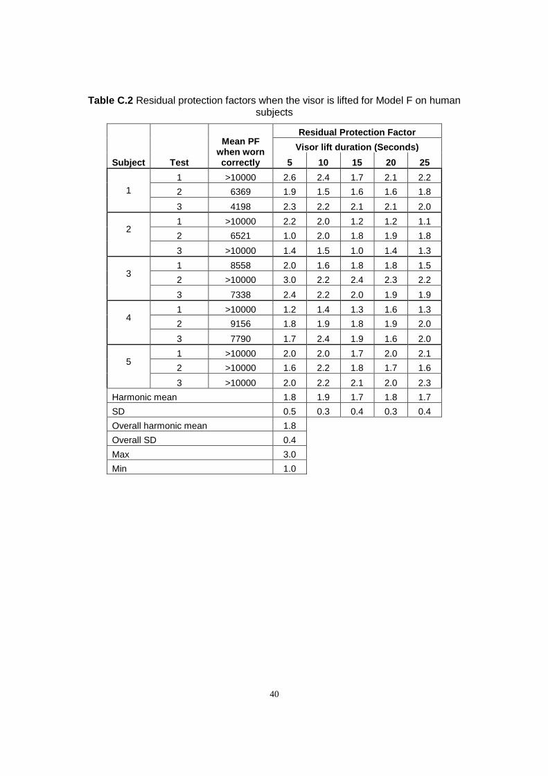
40
Table C.2 Residual protection factors when the visor is lifted for Model F on human subjects
Subject Test
Mean PF when worn correctly
Residual Protection Factor
Visor lift duration (Seconds)
5 10 15 20 25
1
1 >10000 2.6 2.4 1.7 2.1 2.2
2 6369 1.9 1.5 1.6 1.6 1.8
3 4198 2.3 2.2 2.1 2.1 2.0
2
1 >10000 2.2 2.0 1.2 1.2 1.1
2 6521 1.0 2.0 1.8 1.9 1.8
3 >10000 1.4 1.5 1.0 1.4 1.3
3
1 8558 2.0 1.6 1.8 1.8 1.5
2 >10000 3.0 2.2 2.4 2.3 2.2
3 7338 2.4 2.2 2.0 1.9 1.9
4
1 >10000 1.2 1.4 1.3 1.6 1.3
2 9156 1.8 1.9 1.8 1.9 2.0
3 7790 1.7 2.4 1.9 1.6 2.0
5
1 >10000 2.0 2.0 1.7 2.0 2.1
2 >10000 1.6 2.2 1.8 1.7 1.6
3 >10000 2.0 2.2 2.1 2.0 2.3
Harmonic mean 1.8 1.9 1.7 1.8 1.7
SD 0.5 0.3 0.4 0.3 0.4
Overall harmonic mean 1.8
Overall SD 0.4
Max 3.0
Min 1.0

41
Table C.3 Protection factors during exposure period for Model A on human subjects
Subject Test
Mean PF when worn correctly
Protection Factor during exposure period
Visor lift duration (Seconds)
5 10 15 20 25
1
1 >10000 6.2 2.0 1.8 2.2 1.6
2 >10000 2.3 1.8 2.3 2.7 1.5
3 6522 2.7 1.7 1.5 1.4 2.3
2
1 >10000 5.6 4.2 3.1 2.6 2.3
2 >10000 4.0 3.5 2.6 2.7 1.7
3 >10000 6.1 6.1 3.1 1.4 1.8
3
1 >10000 4.8 2.5 2.5 1.8 2.1
2 >10000 5.0 2.5 2.6 1.9 2.6
3 >10000 4.1 2.7 2.0 2.1 1.7
4
1 >10000 5.6 4.4 3.4 3.5 2.5
2 >10000 5.2 3.9 2.9 3.7 4.0
3 >10000 3.2 1.9 2.0 1.6 2.2
5
1 >10000 6.1 4.6 3.9 2.7 3.5
2 6684 4.3 3.2 3.5 2.1 2.0
3 >10000 3.8 3.3 2.2 1.9 2.2
Harmonic mean 4.2 2.8 2.4 2.1 2.1
SD 1.2 1.2 0.7 0.7 0.7
Overall harmonic mean 2.6
Overall SD 1.3
Max 6.2
Min 1.4

42
Table C.4 Protection factors during exposure period for Model F on human subjects
Subject Test
Mean PF when worn correctly
Protection Factor during exposure period
Visor lift duration (Seconds)
5 10 15 20 25
1
1 >10000 9.0 4.3 3.0 2.9 2.9
2 6369 2.8 2.4 2.1 2.1 2.2
3 4198 3.8 3.1 2.6 2.9 2.5
2
1 >10000 4.7 3.9 1.9 1.6 1.5
2 6521 2.2 3.1 2.6 2.7 2.3
3 >10000 2.7 2.7 1.9 1.5 1.9
3
1 8558 5.3 3.0 2.9 3.0 2.2
2 >10000 7.8 4.0 4.6 3.5 3.0
3 7338 4.5 3.6 2.8 2.5 2.4
4
1 >10000 2.9 3.0 2.2 2.3 2.0
2 9156 4.3 3.2 3.2 2.6 2.6
3 7790 3.0 3.6 2.6 2.1 2.5
5
1 >10000 5.5 3.3 3.3 3.4 2.9
2 >10000 3.1 4.0 2.7 2.1 2.2
3 >10000 3.7 4.0 3.6 3.4 3.5
Harmonic mean 3.7 3.3 2.6 2.4 2.3
SD 1.9 0.5 0.7 0.6 0.5
Overall harmonic mean 2.8
Overall SD 1.2
Max 9.0
Min 1.5

43
Table C.5 RPE clearance times for Model A on human subjects
Subject Test RPE clearance time (seconds)
Visor lift duration (Seconds)
5 10 15 20 25
1
1 28 16 17 23 14
2 17 13 14 11 12
3 11 8 10 15 16
2
1 16 22 22 17 14
2 20 14 21 10 13
3 15 13 16 12 11
3
1 18 16 16 14 17
2 16 12 12 12 17
3 9 9 11 11 9
4
1 22 30 21 22 24
2 21 25 23 20 19
3 13 17 17 11 12
5
1 16 21 18 19 23
2 13 14 14 13 13
3 13 16 14 12 12
Mean 15.3 14.6 15.4 13.8 14.1
SD 4.8 5.9 4.0 4.3 4.3
Overall mean 14.6
Overall SD 4.7
Max 30.0
Min 8.0

44
Table C.6 RPE clearance times for Model F on human subjects
Subject Test RPE clearance time (seconds)
Visor lift duration (Seconds)
5 10 15 20 25
1
1 17 16 20 14 16
2 14 15 13 15 13
3 14 12 12 13 12
2
1 16 22 20 19 18
2 16 15 22 13 13
3 14 13 15 12 14
3
1 20 17 15 20 19
2 18 14 19 15 14
3 12 12 11 11 11
4
1 26 27 24 25 25
2 25 20 24 20 18
3 22 19 16 17 17
5
1 21 22 22 23 22
2 14 14 14 11 11
3 12 15 16 18 15
Mean 16.4 16.0 16.5 15.4 15.0
SD 4.5 4.3 4.3 4.3 4.0
Overall mean 15.8
Overall SD 4.2
Max 27.0
Min 11.0

Published by the Health and Safety Executive 08/15

Investigation into exposure when the visor of air fed RPE is raised during spraying
Health and Safety Executive
RR1064
www.hse.gov.uk
Air-fed visors (AFV) are commonly used within the Motor Vehicle Repair (MVR) trade for protection against exposure to isocyanate paints. However, a common practice amongst paint sprayers is to flip up the visor of their AFV immediately after spraying to check the quality of the paint finish. This may be only for a few seconds but if repeated numerous times during a work shift, this could potentially result in a significant increase in exposure. The aim of this project was to determine the reduction in protection and thus potential increase in exposure when the visor is lifted and to explore potential engineering solutions (by modifying the AFV design) to prevent exposure during any visor lift.
The results clearly demonstrate that lifting the visor whilst still within a contaminated atmosphere had a significant detrimental effect on the protection afforded by the AFV. Mean protection factors were measured at 1.7 in the lifted position and at 2.7 over the whole of the exposure period (from start of the lift to recovery of protection after refitting). This latter figure equates to a 15 fold increase in exposure when related to the assigned protection factor of40 for AFV when used correctly.
This report and the work it describes were funded by the Health and Safety Executive (HSE). Its contents, including any opinions and/or conclusions expressed, are those of the authors alone and do not necessarily reflect HSE policy.