investigation geotechnical c appendix - city of newport beach blvd and 32n… · geotechnical...
TRANSCRIPT

APPEN
DIX C – GEO
TECHNICAL INVESTIGATION

Draft Initial Study/Mitigated Negative Declaration for Newport Boulevard and 32nd Street Modification Project City of Newport Beach, California
This page is intentionally blank.

GEOTECHNICAL EVALUATION NEWPORT BOULEVARD AND
32ND STREET MODIFICATIONS NEWPORT BEACH, CALIFORNIA
PREPARED FOR: VA Consulting, Inc.
6400 Oak Canyon, Suite 150 Irvine, California 92618
PREPARED BY: Ninyo & Moore
Geotechnical and Environmental Sciences Consultants 475 Goddard, Suite 200 Irvine, California 92618
October 23, 2013 Project No. 208665001

October 23, 2013 Project No. 208665001
Mr. Jeff Wilkerson VA Consulting, Inc. 6400 Oak Canyon, Suite 150 Irvine, California 92618
Subject: Geotechnical Evaluation Newport Boulevard and 32nd Street Modifications Newport Beach, California
Dear Mr. Wilkerson:
Enclosed please find our report presenting the results of our geotechnical evaluation for the Newport Boulevard and 32nd Street Modifications project in Newport Beach, California. Our evaluation was performed to assess the soil and pavement conditions at the project site and to develop geotechnical recommendations for the design and the construction of the proposed improvements. This report presents our geotechnical findings, conclusions, and recommendations relative to the project.
Ninyo & Moore appreciates the opportunity to be of service on this project.
Respectfully submitted, NINYO & MOORE
Jennifer Schmidt, PG Project Geologist
Daniel Chu, PhD, PE, GE Chief Geotechnical Engineer
Lawrence Jansen, PG, CEG Principal Geologist
JRS/LTJ/DBC/lr/sc
Distribution: (1) Addressee (via e-mail)

Newport Boulevard and 32nd Street October 23, 2013 Newport Beach, California Project No. 208665001
208665001 R Geo Eval.doc i
TABLE OF CONTENTS
Page 1. INTRODUCTION ....................................................................................................................1
2. SCOPE OF SERVICES ............................................................................................................1
3. SITE DESCRIPTION AND PROPOSED CONSTRUCTION ................................................2
4. SUBSURFACE EXPLORATION AND LABORATORY TESTING ....................................2
5. SUBSURFACE CONDITIONS ...............................................................................................3
6. GROUNDWATER ...................................................................................................................4
7. CONCLUSIONS ......................................................................................................................4
8. RECOMMENDATIONS ..........................................................................................................5 8.1. Earthwork .....................................................................................................................5
8.1.1. Pre-Construction Conference ..............................................................................5 8.1.2. Site Preparation ...................................................................................................5 8.1.3. Excavation Characteristics ..................................................................................6 8.1.4. Braced Excavations .............................................................................................6 8.1.5. Construction Dewatering ....................................................................................7 8.1.6. Excavation Bottom Stability ...............................................................................7 8.1.7. Trench Backfill....................................................................................................8 8.1.8. Modulus of Soil Reaction for Pipe Design .........................................................8
8.1.9. Lateral Earth Pressures for Thrust Blocks ..........................................................9 8.2. Pavement Improvements ..............................................................................................9
8.2.1. Asphalt Overlay ................................................................................................10 8.2.2. New Pavement Construction .............................................................................11 8.2.3. Material Specifications......................................................................................11
8.3. Corrosion ....................................................................................................................12 8.4. Concrete ......................................................................................................................12
9. CONSTRUCTION OBSERVATION ....................................................................................13
10. LIMITATIONS .......................................................................................................................13
11. REFERENCES .......................................................................................................................15
Tables Table 1 – Existing Pavement Sections .............................................................................................3 Table 2 – Structural Pavement Recommendations ........................................................................10

Newport Boulevard and 32nd Street October 23, 2013 Newport Beach, California Project No. 208665001
208665001 R Geo Eval.doc ii
Figures Figure 1 – Site Location Figure 2 – Boring Locations Figure 3 – Lateral Earth Pressures for Braced Excavation Below Groundwater (Granular Soil) Figure 4 – Thrust Block Lateral Earth Pressure Diagram
Appendices Appendix A – Boring Logs Appendix B – Laboratory Testing

Newport Boulevard and 32nd Street October 23, 2013 Newport Beach, California Project No. 208665001
208665001 R Geo Eval.doc 1
1. INTRODUCTION
In accordance with your request, we have performed a geotechnical evaluation for the proposed
Newport Boulevard and 32nd Street Modifications project in Newport Beach, California
(Figure 1). The project will include pavement improvements and roadway widening along
Newport Boulevard and at the intersection of Newport Boulevard and 32nd Street. The purpose of
our study was to evaluate the subsurface conditions and to provide geotechnical design
parameters for the project. This report presents the results of our study, including our findings
and recommendations relative to the geotechnical aspects of the project.
2. SCOPE OF SERVICES
The scope of our geotechnical services included the following:
Attendance at a project kick-off meeting with the client and City of Newport Beach representatives to discuss project details.
Project coordination, planning, permit acquisition, and scheduling of the subsurface exploration.
Review of readily available background data, including in-house geotechnical data, published geotechnical literature, aerial photographs, geologic maps, and project-related plans provided by the client.
Reconnaissance of the site to locate proposed borings and coordinate with Underground Services Alert for underground utility location.
Traffic control in general accordance with the Work Area Traffic Control Handbook.
Subsurface exploration consisting of the drilling, logging, and sampling of six small-diameter hollow-stem auger exploratory borings. The borings were logged by our representative and bulk and relatively undisturbed samples were collected at selected intervals. The borings were backfilled with on-site soil after drilling and the soil samples were returned to our laboratory for testing.
Laboratory testing of selected, representative soil samples to evaluate R-value and corrosivity.
Data compilation and engineering analysis of the information obtained from our background review, subsurface evaluation, and laboratory testing.

Newport Boulevard and 32nd Street October 23, 2013 Newport Beach, California Project No. 208665001
208665001 R Geo Eval.doc 2
Preparation of this geotechnical report presenting our findings, conclusions, and recommendations pertaining to the design and construction of the proposed roadway improvements.
3. SITE DESCRIPTION AND PROPOSED CONSTRUCTION
The project site is located in a commercial area on the Balboa Peninsula. Outlying properties are
predominantly residential. The proposed street modifications are located on Newport Boulevard
between 30th Street and Via Lido and on 32nd Street at the intersection of Newport Boulevard.
The site topography is relatively flat with ground surface elevations ranging from approximately
4 to 8 feet above mean sea level. Pavement distress observed on Newport Boulevard between
32nd Street and Finley Avenue included moderate longitudinal and alligator cracking, moderate
raveling, and minor potholes. The majority of the cracking and potholes along this section have
been previously patched and/or sealed. Pavements in the remainder of the roadway modification
area are generally in good condition with some minor transverse cracking.
Concept plans (VA Consulting, 2013) show proposed improvements consisting of the widening
and modifications of Newport Boulevard and 32nd Street to include an additional through-lane on
northbound Newport Boulevard from 30th Street to 32nd Street and on southbound Newport
Boulevard from Via Lido to 32nd Street (Figure 2). Curbside parking stalls will be removed and
concrete bike lanes will be added. An existing building at the northwest corner of Newport
Boulevard and 32nd Street will be removed to accommodate road widening at this location and
the addition of a parking lot with sixteen new parking stalls. Other improvements will include
raised median island construction, median landscaping and irrigation, striping, signing, and
minor utility trenching for laterals.
4. SUBSURFACE EXPLORATION AND LABORATORY TESTING
Our subsurface evaluation was performed on September 12, 2013, and consisted of the drilling,
logging, and sampling of six small-diameter borings. The borings were advanced to depths of up
to approximately 6½ feet. A representative from our firm logged the borings and obtained bulk
and relatively undisturbed soil samples at selected depths for laboratory testing. The approximate

Newport Boulevard and 32nd Street October 23, 2013 Newport Beach, California Project No. 208665001
208665001 R Geo Eval.doc 3
locations of the borings are presented on Figure 2. Logs of the borings are presented in
Appendix A.
Geotechnical laboratory testing was performed on representative soil samples to evaluate R-
value and soil corrosivity. The results of the laboratory testing are presented in Appendix B.
5. SUBSURFACE CONDITIONS
Review of referenced geologic maps (Morton, 2004) indicates that the site is underlain by eolian
and estuarine alluvial deposits. These deposits are described as consisting of unconsolidated
sand, silt, and clay with variable amounts of organic matter. The subsurface conditions
encountered at our boring locations are summarized below. Detailed descriptions of the
subsurface conditions are presented on the boring logs in Appendix A.
Measurements of the existing pavement sections were obtained at our boring locations. The
pavement sections encountered consisted primarily of asphalt concrete over aggregate base.
Portland cement concrete (PCC) was encountered below the asphalt concrete in borings B-2 and
B-5. The thickness of the PCC and presence of base at these locations is unknown due to drilling
refusal in the concrete. Table 1 presents a summary of the existing pavement sections
encountered in our exploratory borings. Variable thicknesses should be anticipated.
Table 1 – Existing Pavement Sections
Boring No. Street Asphalt Concrete (inches)
Aggregate Base (inches)
B-1 Newport Boulevard - Southbound 10 4 B-2 Newport Boulevard - Northbound 11 Unknown* B-3 Newport Boulevard - Southbound 4.5 4 B-4 Newport Boulevard - Northbound 6 12 B-5 Newport Boulevard - Northbound 6 Unknown* B-6 32nd Street - Westbound 6.5 5
*Drilling refusal in concrete; thickness unknown
The pavements were underlain by fill soil and alluvial deposits to the depths explored. In
general, the soil conditions beneath the pavements were comprised of moist to saturated,

Newport Boulevard and 32nd Street October 23, 2013 Newport Beach, California Project No. 208665001
208665001 R Geo Eval.doc 4
very loose to medium dense, silty sand. Scattered, relatively minor amounts of clayey sand,
sandy silt and clayey silt were also observed at the boring locations.
6. GROUNDWATER
Groundwater was encountered in borings B-1, B-3, B-4 and B-6 at depths ranging from
approximately 3 to 5 feet below the ground surface at the time of drilling. It should be noted that
the depths to groundwater were evaluated at the time of drilling and stabilized groundwater
elevations were not established; therefore, groundwater may be shallower than encountered at
the time of drilling. In addition, fluctuations in the level of groundwater will occur due to tidal
fluctuations, variations in ground surface topography, subsurface stratification, rainfall, irrigation
practices, and other factors which may not have been evident at the time of our field evaluation.
7. CONCLUSIONS
Based on the results of our geotechnical evaluation, it is our opinion that the proposed
improvements are feasible, provided the recommendations presented in this report are
incorporated into the design and construction of the project. Our conclusions are based on the
findings of this evaluation and are as follows:
The project site is underlain by fill and alluvium generally consisting of very loose to medium dense, silty sand with minor amounts of clayey sand and sandy to clayey silt.
The on-site granular soils are generally suitable for use as structural backfill provided deleterious materials are removed. Soil excavated from below groundwater levels will be wet and will involve drying to be suitable for compaction.
During our subsurface evaluation, groundwater was encountered at depths ranging from approximately 3 to 5 feet below the existing ground surface. Groundwater should be anticipated at depths of approximately 3 feet or less. Trench excavations that extend below groundwater will involve dewatering in order to construct the proposed improvements under a dry condition.
Trench excavations that extend below groundwater or deeper than 4 feet will involve temporary shoring to support the excavation sidewalls and to reduce the potential settlement that could affect the roadway and adjacent structures and/or pipelines. Shoring should be used in accordance with Occupational Safety Health Administration (OSHA) regulations. The on-site soils should be considered as Type C soils in accordance with OSHA regulations.

Newport Boulevard and 32nd Street October 23, 2013 Newport Beach, California Project No. 208665001
208665001 R Geo Eval.doc 5
Existing utilities and structures are present along the project alignment that will involve protection in-place during construction. The contractor should take care to keep from damaging and/or undermining the utilities and adjacent structures.
Our limited laboratory corrosion testing indicates that the on-site soils should be considered non-corrosive based on California Department of Transportation (Caltrans, 2003) corrosion guidelines.
8. RECOMMENDATIONS
The recommendations presented in the following sections provide general geotechnical criteria
regarding the design and construction of the proposed roadway modification project. These
recommendations are based on our evaluation of the site geotechnical conditions and our
understanding of the planned improvements.
8.1. Earthwork
We anticipate that earthwork for the project will include relatively shallow excavations of
approximately 2 feet or less for new pavements, pavement subgrade preparation, trenching
and backfill for utility laterals, and removal of foundations and abandoned utilities for new
parking lot construction. Earthwork operations should be performed in accordance with the
following recommendations, as well as the grading specifications of the governing agencies.
8.1.1. Pre-Construction Conference
We recommend that a pre-construction conference be held. The owner and/or their
representative, the governing agencies’ representatives, the civil engineer, Ninyo &
Moore, and the contractor should attend to discuss the work plan, project schedule, and
excavation issues.
8.1.2. Site Preparation
Prior to roadway improvements, the area should be cleared of existing surface
obstructions, reflectors, and other deleterious materials. If pavement reconstruction is
being performed, existing utilities should be re-routed or protected from damage by
construction activities. Holes resulting from the removal of buried obstructions that
extend below the finish grade should be backfilled with compacted fill.

Newport Boulevard and 32nd Street October 23, 2013 Newport Beach, California Project No. 208665001
208665001 R Geo Eval.doc 6
8.1.3. Excavation Characteristics
Based on our field exploration and experience, we anticipate that excavation within the
existing fill and alluvium at the site may be accomplished with conventional
earthmoving equipment in good condition. Excavations that extend below groundwater
will be unstable and subject to caving. Shoring is anticipated for excavations that
encounter groundwater.
8.1.4. Braced Excavations
Trenches or other excavations that extend below groundwater and/or deeper than
approximately 4 feet should be shored. Shoring systems should be installed prior to
excavating below groundwater to avoid caving and undermining of adjacent
improvements. Shoring systems with continuous sheeting should be provided. Shoring
systems should be designed using the lateral earth pressures presented on Figure 3 for
braced excavations below groundwater in granular soil. The recommended design
pressures are based on the assumptions that the shoring system is constructed without
raising the ground surface elevation behind the shoring, that there are no surcharge
loads, such as soil stockpiles and construction materials, and that no loads act above a
1:1 (horizontal to vertical) plane extending up and back from the base of the sheet pile
system. For shoring subjected to the above-mentioned surcharge loads, the contractor
should include the effect of these loads on the lateral earth pressures against the shoring
system.
The contractor should retain a qualified and experienced engineer to design the shoring
system. The shoring parameters presented in this report are minimum requirements, and
the contractor should evaluate the adequacy of these parameters and make the required
modifications for their design. We recommend that the contractor take appropriate
measures to protect workers. OSHA requirements pertaining to worker safety should be
observed. The on-site soils should be considered as soil Type C in accordance with
OSHA requirements.

Newport Boulevard and 32nd Street October 23, 2013 Newport Beach, California Project No. 208665001
208665001 R Geo Eval.doc 7
8.1.5. Construction Dewatering
Groundwater is anticipated at depths of approximately 3 feet or less and excavations
that extend below groundwater will involve dewatering. Dewatering may include
pumping of groundwater from well points within or outside of the shored excavation.
Dewatering should be limited to not more than approximately 2 feet below the bottom
of excavations. The dewatering system design should be performed by a specialty
dewatering contractor. Disposal of groundwater should be performed in accordance
with guidelines of the Regional Water Quality Control Board.
8.1.6. Excavation Bottom Stability
Excavations close to or below the groundwater (before or after dewatering) will
encounter wet and potentially unstable ground conditions. Wet soils may be subject to
pumping under equipment loading.
Where new pavement construction occurs, subgrade soils close to groundwater may be
subject to pumping under compaction equipment loads. Repeated compaction effort
and/or vibratory compaction equipment may result in pumping and unstable subgrade
conditions. In the event pumping/unstable subgrade conditions occur due to shallow
groundwater conditions, we recommend no vibratory compaction equipment. Static
smooth drum rollers or other non-vibratory equipment should be used for compaction.
If unstable subgrade conditions persist, additional stabilization measures may be
appropriate. Additional stabilization may involve geogrid reinforcement, over-
excavation and replacement with crushed aggregate, or other methods.
Recommendations for subgrade stabilization should be prepared by Ninyo & Moore at
the time of construction based on evaluation of the conditions encountered.
The bottoms of the trenches that are near or below groundwater will be relatively
unstable. In general, unstable bottom conditions may be mitigated by overexcavating
the trench bottom 1 to 2 feet and replacing with gravel wrapped in a geotextile filter
fabric (Mirafi 140N or equivalent). Recommendations for stabilizing excavation

Newport Boulevard and 32nd Street October 23, 2013 Newport Beach, California Project No. 208665001
208665001 R Geo Eval.doc 8
bottoms should be based on evaluation in the field by Ninyo & Moore at the time of
construction.
8.1.7. Trench Backfill
Soils encountered at the site should generally be suitable for reuse as backfill for
trenches provided they are free of organic material, clay lumps, debris, and rocks larger
than approximately 4 inches in diameter. Excavations that extend to groundwater will
involve wet soils. Wet soils should be processed to near-optimum moisture content prior
to their placement as trench backfill. Fill material imported to the site (if any), should be
granular, non-expansive soil, and free of trash, debris, roots, vegetation, or other
deleterious materials. “Non-expansive” soils can be defined as having a “very low”
expansion potential in accordance with the California Building Code (CBC) (an
expansion index ranging from 0 to 20). Fill should generally be free of rocks or hard
lumps of material in excess of 4 inches in diameter. Rocks or hard lumps larger than
approximately 4 inches in diameter should be broken into smaller pieces or should be
removed from the site. Materials for use as imported structural fill should be evaluated
by Ninyo & Moore prior to importing.
Backfill should be compacted to a relative compaction of 90 percent as evaluated
ASTM International (ASTM) D 1557. Lift thickness for backfill will depend on the type
of compaction equipment utilized, but fill should generally be placed in lifts not
exceeding 8 inches in loose thickness. Special care should be exercised to avoid
damaging utilities during compaction of the backfill.
8.1.8. Modulus of Soil Reaction for Pipe Design
The modulus of soil reaction is used to characterize the stiffness of soil along the sides
of buried flexible pipelines for the purpose of evaluating deflection caused by the
weight of the backfill above the pipe. We recommend that a modulus of soil reaction of
1,000 pounds per square inch be used for design for access pits exposing granular soil in
the pipe zone, provided that granular pipe zone backfill material is placed adjacent to
the pipe, as previously recommended.

Newport Boulevard and 32nd Street October 23, 2013 Newport Beach, California Project No. 208665001
208665001 R Geo Eval.doc 9
8.1.9. Lateral Earth Pressures for Thrust Blocks
Thrust restraint for water pressure inside the pipe may be achieved by transferring the
thrust force to the soil outside the pipe through a thrust block. Thrust blocks may be
designed using the lateral passive earth pressures presented on Figure 4.
8.2. Pavement Improvements
Pavement designs were prepared for structural pavement overlays and new pavement
construction. The pavement designs were based on our evaluation of existing pavement
sections, the subgrade soil conditions and our laboratory testing.
The R-value characteristics of the subgrade soils were evaluated from representative soil
samples obtained from our exploratory borings. Laboratory R-value testing indicates that the
R-values of the materials encountered in our borings ranged from 71 to 77. Considering the
possible soil variation throughout the study area, an R-value of 60 was used for the design.
Traffic index (TI) values were provided to us by VA Consulting and included a TI of 7.0 for
the number 1 lanes and a TI of 9.5 for the number 2 and 3 lanes and all lanes south of 32nd
Street. In addition, we assumed a TI of 5.0 for the new parking lot construction. Our
pavement analysis was performed using the methodology outlined by the Institute for
Transportation Studies (Institute for Transportation Studies, 1984) and the Highway Design
Manual (Caltrans, 2008). The analysis assumes an approximately 10-year design life for
pavement overlays and a 20-year design life for new pavements.
Based on the design R-values and TIs, recommendations for pavement overlays and new
pavement construction are provided in Table 2. The recommended pavement overlay
thicknesses do not include pavement grinding. To maintain the recommended pavement
section, the depth of grinding should be added to the pavement overlay thickness. It should
be noted that the pavement overlay recommendations were based on the existing pavement
section measured in boring B-3, which was the relatively thinner pavement section
encountered. The pavement overlay recommendations also include a Rubberized Hot Mix
Asphalt (RHMA) alternative. The RHMA alternative allows for thinner overlay that
maintains the design structural section. Factors such as existing grade/drainage conditions,

Newport Boulevard and 32nd Street October 23, 2013 Newport Beach, California Project No. 208665001
208665001 R Geo Eval.doc 10
construction constraints, and economic considerations should be considered in selecting the
appropriate pavement alternative.
Table 2 – Structural Pavement Recommendations
Traffic Index
Structural Overlay Options New Construction
HMA (feet)
RHMA-G/ DGHMA
(feet)
AC/AB or AC/CMB
(feet)
Full Depth AC (feet)
PCC (feet)
5.0 -- -- 0.20/0.35 0.30 0.45
7.0 0.25 0.15/0 0.35/0.35 0.45 0.60
9.5 0.45 0.15/0.15 0.5/0.35 0.65 0.65
Notes: AC – Asphalt Concrete AB – Caltrans Class II Aggregate Base CMB – Crushed Miscellaneous Base DGHMA – Dense Graded HMA HMA – Hot Mix Asphalt PCC – Portland Cement Concrete RHMA-G – Gap Graded Rubberized HMA
8.2.1. Asphalt Overlay
The purpose of an asphalt concrete overlay is to improve the performance and lengthen
the remaining design life of the existing pavement structural section. Pavement grinding
should be performed prior to the overlay to provide a fresh pavement surface. After
grinding, cracks approximately 1/8 inch wide or more should be sealed with a crack
sealant. Then the surface should be cleaned of loose debris and a tack coat of liquid
asphalt consisting of a 0.1 gallon per square yard application of SS-1, or equivalent,
should be applied. In order to maintain pavement grades along concrete gutters, existing
pavements are typically cold-milled along the gutters to allow for the placement of the
recommended overlay thickness while maintaining pavement grades at the gutter
interface.
A qualified subcontractor should install the asphalt overlay in accordance with the
recommendations of the Asphalt Institute, or equivalent association. Routine

Newport Boulevard and 32nd Street October 23, 2013 Newport Beach, California Project No. 208665001
208665001 R Geo Eval.doc 11
maintenance should be expected including periodic sealing of the pavement and repair
of cracks or other isolated distress. The selected alternative for the project depends on a
number of variables, including availability and cost of different materials, construction
requirements/constraints, and site-specific soil conditions.
8.2.2. New Pavement Construction
In areas where the roadway will be widened or the existing pavement section is
reconstructed, new pavement sections consisting of asphalt concrete over aggregate
base, full-depth asphalt concrete, or PCC may be used as recommended in Table 2.
Prior to placement of the new structural pavement section, the subgrade soils should be
prepared appropriately. The upper approximately 12 inches of the subgrade beneath new
pavements should be scarified, moisture conditioned, and re-compacted to a relative
compaction of 90 percent as evaluated by ASTM test method D1557. If a full-depth AC
section is selected, the pavement subgrade should be compacted to 95 percent or more
relative compaction. The subgrade compaction should also result in a non-yielding
condition to allow for pavement construction. In the event unstable subgrade conditions
are encountered, as described in the previous earthwork sections of this report,
stabilization measures should be performed to achieve a non-yielding condition for
pavement construction.
8.2.3. Material Specifications
Asphalt concrete should conform to the latest edition of the Standard Specifications for
Public Works Construction Section 203-1 for asphalt and 203-6 for aggregates. Class 2
aggregate base should conform to the latest edition of the State of California Standard
Specifications, Section 26-1.02A. Crushed Miscellaneous Base should conform to the
latest edition of the Standard Specifications for Public Works Construction,
Section 200-2.4. Hot-Mix Asphalt (HMA) materials should conform to the Standard
Specifications for Public Works Construction “Greenbook,” Section 203-6. Placement
and rolling of HMA materials should conform to the Greenbook Section 302-5. RHMA
materials should conform to Greenbook Section 203-11.

Newport Boulevard and 32nd Street October 23, 2013 Newport Beach, California Project No. 208665001
208665001 R Geo Eval.doc 12
Base material should be placed at a relative compaction of 95 percent or more as
evaluated by ASTM D 1557. Grinding and recycling existing asphalt concrete and
existing base material may be considered as a potential source of Crushed
Miscellaneous Base material provided they meet the requirements in the Standard
Specifications.
8.3. Corrosion
Laboratory testing was performed to evaluate pH, minimum electrical resistivity, water-
soluble chloride content, and water-soluble sulfate content of site soils. The pH and
minimum electrical resistivity tests were performed in accordance with California Test
Method 643. Sulfate and chloride content tests were performed in accordance with
California Test Methods 417 and 422, respectively. The laboratory results are presented in
Appendix B.
The results of our limited corrosivity testing indicated an electrical resistivity of
approximately 2,390 to 5,505 ohm-centimeters, a soil pH of approximately 8.5 to 8.8, a
chloride content of approximately 80 to 260 parts per million (ppm), and a sulfate content of
approximately 0.003 to 0.004 percent (25 to 40 ppm). Based on the laboratory test results
and Caltrans (2003) corrosion criteria, the project site can be classified as non-corrosive,
which is defined as having earth materials with less than 500 ppm chlorides, less than 0.20
percent sulfates (i.e., 2,000 ppm), an electrical resistivity of 1,000 ohm-centimeters or more,
and a pH of 5.5 or greater.
The site soils may, therefore, be considered to be non-corrosive to ferrous metals. Corrosion
protection for improvements in contact with soil be designed by a corrosion engineer.
8.4. Concrete
Concrete in contact with soil or water that contains high concentrations of soluble sulfates
can be subject to chemical and/or physical deterioration. Based on the CBC criteria (2010)
and American Concrete Institute (ACI) criteria (ACI, 2011), the potential for sulfate attack is
negligible for water-soluble sulfate contents in soil ranging less than 1,000 ppm. As

Newport Boulevard and 32nd Street October 23, 2013 Newport Beach, California Project No. 208665001
208665001 R Geo Eval.doc 13
indicated above, the soil samples tested for this evaluation indicate a water-soluble sulfate
content of 25 to 40 ppm. Accordingly, the on-site soils are considered to have a negligible
potential for sulfate attack.
In order to reduce the potential for shrinkage cracks in the concrete during curing, we
recommend that the concrete be placed with a slump of 4 inches based on ASTM C 143. The
slump should be checked periodically at the site prior to concrete placement. The structural
engineer should be consulted for additional concrete specifications.
9. CONSTRUCTION OBSERVATION
Ninyo & Moore should observe and test fill placement and compaction. The frequency of testing
and the time of observation will vary depending on the contractor’s method of operation and
quality of work, as well as the requirements of the governing agency.
The recommendations provided in this report are based on the assumption that Ninyo & Moore
will provide geotechnical observation and testing services during construction. In the event that
the services of Ninyo & Moore are not used during construction, we request that the selected
consultant provide the City of Newport Beach Public Works with a letter (with a copy to Ninyo
& Moore) indicating that they fully understand Ninyo & Moore’s recommendations, and that
they are in full agreement with the design parameters and recommendations contained in this
report.
10. LIMITATIONS
The field evaluation, laboratory testing, and geotechnical analyses presented in this geotechnical
report have been conducted in general accordance with current practice and the standard of care
exercised by geotechnical consultants performing similar tasks in the project area. No warranty,
expressed or implied, is made regarding the conclusions, recommendations, and opinions
presented in this report. There is no evaluation detailed enough to reveal every subsurface
condition. Variations may exist and conditions not observed or described in this report may be
encountered during construction. Uncertainties relative to subsurface conditions can be reduced
through additional subsurface exploration. Additional subsurface evaluation will be performed

Newport Boulevard and 32nd Street October 23, 2013 Newport Beach, California Project No. 208665001
208665001 R Geo Eval.doc 14
upon request. Please also note that our evaluation was limited to assessment of the geotechnical
aspects of the project, and did not include evaluation of structural issues, environmental
concerns, or the presence of hazardous materials.
This document is intended to be used only in its entirety. No portion of the document, by itself, is
designed to completely represent any aspect of the project described herein. Ninyo & Moore
should be contacted if the reader requires additional information or has questions regarding the
content, interpretations presented, or completeness of this document.
This report is intended for design purposes only and may not provide sufficient data to prepare
an accurate bid by some contractors. It is suggested that the bidders and their geotechnical
consultant perform an independent evaluation of the subsurface conditions in the project areas.
The independent evaluations may include, but not be limited to, review of other geotechnical
reports prepared for the adjacent areas, site reconnaissance, and additional exploration and
laboratory testing.
Our conclusions, recommendations, and opinions are based on an analysis of the observed site
conditions. If geotechnical conditions different from those described in this report are
encountered, our office should be notified, and additional recommendations, if warranted, will be
provided upon request. It should be understood that the conditions of a site can change with time
as a result of natural processes or the activities of man at the subject site or nearby sites. In
addition, changes to the applicable laws, regulations, codes, and standards of practice may occur
due to government action or the broadening of knowledge. The findings of this report may,
therefore, be invalidated over time, in part or in whole, by changes over which Ninyo & Moore
has no control.
This report is intended exclusively for use by the client. Any use or reuse of the findings,
conclusions, and/or recommendations of this report by parties other than the client is undertaken
at said parties’ sole risk.

Newport Boulevard and 32nd Street October 23, 2013 Newport Beach, California Project No. 208665001
208665001 R Geo Eval.doc 15
11. REFERENCES
American Concrete Institute (ACI), 2011, ACI Manual of Concrete Practice.
Asphalt Institute, 1989, The Asphalt Handbook, Manual Series No. 4 (MS-4), 1989 Edition.
California Building Standards Commission, 2010, California Building Code (CBC): California Code of Regulations, Title 24, Part 2, Volumes 1 and 2.
California Department of Conservation, Division of Mines and Geology, State of California, 1997a, (Revised 2001), Seismic Hazard Zone Report for the Anaheim and Newport Beach 7.5-Minute Quadrangles, Orange County, California: Seismic Hazard Zone Report 003.
California Department of Conservation, Division of Mines and Geology, State of California, 1997b, Seismic Hazard Zones Official Map, Newport Beach Quadrangle, 7.5-Minute Series, Scale 1:24,000, Open-File Report 97-08, dated April 7.
California Department of Transportation, 1995, Standard Specifications, dated July. California Department of Transportation, 2003, Corrosion Guidelines, Version 1.0, dated
September. California Department of Transportation, 2008, Highway Design Manual: Fifth Edition, dated
September 1.
Google Earth, 2013, Website for Aerial Photographs; website: http://maps.google.com/.
Institute for Transportation Studies, 1984, Pavement Maintenance and Rehabilitation: Techniques Using Asphalt, University of California Berkeley, Course Notes.
Joint Cooperative Committee of the Southern California Chapter of the American Public Works Association and Southern California Districts of the Associated General Contractors of California, 2012, “Greenbook,” Standard Specifications for Public Works Construction: BNI Building News, Los Angeles, California.
Morton, D.M., 2004, Preliminary Digital Geologic Map of the Santa Ana 30’ x 60’ Quadrangle, Southern California, Version 2.0: United States Geological Survey, Open-File Report 99-172, Scale 1:100,000.
Ninyo & Moore, 2012, Proposal for Geotechnical Consulting Services, Newport Boulevard and 32nd Street Modification Project, Newport Beach, California, Proposal No. P-15457, dated March 20.
United States Geological Survey, 1965 (Photorevised 1981), Newport Beach, California Quadrangle Map, 7.5 Minute Series: Scale 1:24,000.
VA Consulting, Inc., 2013, Concept Plan for Newport Boulevard and 32nd Street Widening, Alternative 5, dated July 2.

Newport Boulevard and 32nd Street October 23, 2013 Newport Beach, California Project No. 208665001
208665001 R Geo Eval.doc 16
AERIAL PHOTOGRAPHS
Source Date Scale Flight Numbers
USDA 6-2-53 1:20,000 AXK-6K 67 & 68

SITE
FIGURE
1
PROJECT NO.
208665001
NEWPORT BOULEVARD AND 32ND STREET MODIFICATIONS
NEWPORT BEACH, CALIFORNIA
DATE
10/13
0 2,400 4,800
SCALE IN FEET
NOTE: DIMENSIONS, DIRECTIONS AND LOCATIONS ARE APPROXIMATE.
Map © Rand McNally, R.L.07-S-129
N
SITE LOCATION
208665001_S
L.d
wg
15:33:22 10/22/2013 G
K

B-1TD=6.5
B-6TD=3.5
B-2TD=1.1
B-3TD=6.5
B-4TD=6.5
B-5TD=0.8
FIGURE
2
PROJECT NO.
208665001
DATE
10/13NOTE: DIMENSIONS, DIRECTIONS AND LOCATIONS ARE APPROXIMATE.
150 300
SCALE IN FEET
0
BORING;TD=TOTAL DEPTH IN FEET
B-6TD=3.5
LEGEND
BORING LOCATIONS
REFERENCE: VA CONSULTING, INC., 2013, CONCEPT PLAN FOR NEWPORT BOULEVARD AND 32ND STREET WIDENING, ALTERNATIVE 5, DATED JULY 2.
208665001_B
L.d
wg
15:43:22 10/22/2013 G
K
NEWPORT BOULEVARD AND 32ND STREET MODIFICATIONS
NEWPORT BEACH, CALIFORNIA

LATERAL EARTH PRESSURES FOR BRACED EXCAVATION
pP
h
Pa
+
sP
NOTES:
APPARENT LATERAL EARTH PRESSURES, P AND P P = 24 h psf
1.
CONSTRUCTION TRAFFIC INDUCED SURCHARGE PRESSURE, P P = 120 psf
2.
P = 62.4 h psfWATER PRESSURE, P 3.
4.
SURCHARGES FROM EXCAVATED SOIL OR5.CONSTRUCTION MATERIALS ARE NOT INCLUDED
BELOW GROUNDWATER (GRANULAR SOIL)
+ 2
1h
2Pw
Pa1
1
2
1P = 12 h psf
PASSIVE PRESSURE, P P = 180 D psf
D
6.
GROUNDWATER TABLE, h IS ASSUMED TO BE 3 FEET
2
7.
H, h , h AND D ARE IN FEET21
a a 2a
a
s
w
p
w
p
s
FIGURE
3
PROJECT NO. DATE
SHORING
BRACES
208665001
10/13
H
21
208665001_D
-E
P.d
wg
16:27:22 10/22/2013 G
K
NEWPORT BOULEVARD AND 32ND STREET MODIFICATIONS
NEWPORT BEACH, CALIFORNIA

NOTES:
GROUNDWATER BELOW BLOCK
GROUNDWATER ABOVE BLOCK2.
1.
P = 180 p (D -d )2 2 lb/ft
THRUSTBLOCK
d (VARIES)
P
Pp
p
D (VARIES)
3. ASSUMES BACKFILL IS GRANULAR MATERIAL
4. ASSUMES THRUST BLOCK IS ADJACENT TO COMPETENT MATERIAL
FIGURE
4
PROJECT NO. DATE
THRUST BLOCK LATERAL EARTH PRESSURE DIAGRAM
1
Pp2
pP = 1.5 ( D - d )[ 125 h + 58 ( D+d ) ]
GROUNDWATER TABLE6.
D, d AND h ARE IN FEET5.
h
lb/ft
208665001 10/13
208665001_D
-T
B.d
wg
16:28:22 10/22/2013 G
K
NEWPORT BOULEVARD AND 32ND STREET MODIFICATIONS
NEWPORT BEACH, CALIFORNIA

Newport Boulevard and 32nd Street October 23, 2013 Newport Beach, California Project No. 208665001
208665001 R Geo Eval.doc
APPENDIX A
BORING LOGS
Field Procedure for the Collection of Disturbed Samples Disturbed soil samples were obtained in the field using the following method.
Bulk Samples Bulk samples of representative earth materials were obtained from the exploratory borings. The samples were bagged and transported to the laboratory for testing.
Field Procedure for the Collection of Relatively Undisturbed Samples Relatively undisturbed soil samples were obtained in the field using the following method.
The Modified Split-Barrel Drive Sampler The sampler, with an external diameter of 3 inches, was lined with 1-inch-long, thin brass rings with inside diameters of approximately 2.4 inches. The sampler barrel was driven into the ground with the weight of a 140-pound hammer mounted on the drill rig in general accordance with ASTM International (ASTM) D 3550. The driving weight was permitted to fall freely. The approximate length of the fall, the weight of the hammer or bar, and the number of blows per foot of driving are presented on the boring logs as an index to the relative resistance of the materials sampled. The samples were removed from the sampler barrel in the brass rings, sealed, and transported to the laboratory for testing.

TYPICAL NAMES
GWWell graded gravels or gravel-sand mixtures, little or no fines
GPPoorly graded gravels or gravel-sand mixtures, little or no fines
GM Silty gravels, gravel-sand-silt mixtures
GC Clayey gravels, gravel-sand-clay mixtures
SW Well graded sands or gravelly sands, little or no fines
SPPoorly graded sands or gravelly sands, little or no fines
SM Silty sands, sand-silt mixtures
SC Clayey sands, sand-clay mixtures
MLInorganic silts and very fine sands, rock flour, silty or clayey fine sands or clayey silts with slight plasticity
CLInorganic clays of low to medium plasticity, gravelly clays, sandy clays, silty clays, lean clays
OL Organic silts and organic silty clays of low plasticity
MHInorganic silts, micaceous or diatomaceous fine sandy or silty soils, elastic silts
CH Inorganic clays of high plasticity, fat clays
OHOrganic clays of medium to high plasticity, organic silty clays, organic silts
Pt Peat and other highly organic soils
U.S. Standard Sieve Size
Grain Size in Millimeters
BOULDERS Above 12" Above 305
COBBLES 12" to 3" 306 to 76.2
GRAVEL 3" to No. 4 76.2 to 4.76
Coarse 3" to 3/4" 76.2 to 19.1
Fine 3/4" to No. 4 19.1 to 4.76
SAND No. 4 to No. 200 4.76 to 0.075
Coarse No. 4 to No. 10 4.76 to 2.00
Medium No. 10 to No. 40 2.00 to 0.420
Fine No. 40 to No. 200 0.420 to 0.075
SILT & CLAY Below No. 200 Below 0.075
SYMBOL
U.S.C.S. METHOD OF SOIL CLASSIFICATION
FIN
E-G
RA
INE
D S
OIL
S(M
ore
than
1/2
of
soil
<
No.
200
sie
ve s
ize)
U.S.C.S. METHOD OF SOIL CLASSIFICATION
CO
AR
SE
-GR
AIN
ED
SO
ILS
(Mor
e th
an 1
/2 o
f so
il
> N
o. 2
00 S
ieve
Siz
e)
MAJOR DIVISIONS
HIGHLY ORGANIC SOILS
GRAVELS (More than 1/2 of coarse
fraction > No. 4 sieve size
SANDS (More than 1/2 of coarse
fraction < No. 4 sieve size
SILTS & CLAYSLiquid Limit <50
SILTS & CLAYSLiquid Limit >50
GRAIN SIZE CHART
RANGE OF GRAINCLASSIFICATION
PLASTICITY CHART
CH
CL M H & OH
M L & OLCL - M L
0
10
20
30
40
50
60
70
0 10 20 30 40 50 60 70 80 90 100
LIQ UID LIMIT (LL), %
PL
AST
ICIT
Y I
ND
EX
(P
I),
%
Updated Nov. 2011

0
5
10
15
20
XX/XX
SM
CL
Bulk sample.
Modified split-barrel drive sampler.
No recovery with modified split-barrel drive sampler.
Sample retained by others.
Standard Penetration Test (SPT).
No recovery with a SPT.
Shelby tube sample. Distance pushed in inches/length of sample recovered in inches.
No recovery with Shelby tube sampler.
Continuous Push Sample.
Seepage.Groundwater encountered during drilling.Groundwater measured after drilling.
MAJOR MATERIAL TYPE (SOIL):Solid line denotes unit change.
Dashed line denotes material change.
Attitudes: Strike/Dipb: Beddingc: Contactj: Jointf: FractureF: Faultcs: Clay Seams: Shearbss: Basal Slide Surfacesf: Shear Fracturesz: Shear Zonesbs: Shear Bedding Surface
The total depth line is a solid line that is drawn at the bottom of the boring.
BORING LOGExplanation of Boring Log Symbols
PROJECT NO. DATE FIGURE
DE
PTH
(fee
t)
Bul
kS
AM
PLE
SD
riven
BLO
WS/
FOO
T
MO
ISTU
RE
(%)
DR
Y D
EN
SIT
Y (P
CF)
SY
MB
OL
CLA
SS
IFIC
ATI
ON
U.S
.C.S
.
BORING LOG EXPLANATION SHEET
Rev. 11/11

0
5
10
15
20
5
SMSCSM
SM
ASPHALT CONCRETE:Approximately 10 inches thick.BASE:Medium brown, moist, medium dense, silty SAND; few gravel; approximately 4 inchesthick.FILL:Medium brown, moist, medium dense, clayey SAND; trace pieces of brick.Medium brown, moist, medium dense, silty SAND; pockets of sandy CLAY.ALLUVIUM:Yellowish brown, moist, very loose, silty SAND.
@ 4.5': Groundwater was encountered during drilling.Gray; saturated.
Total Depth = 6.5 feet.Groundwater was encountered at 4.5 feet during drilling.Backfilled with on-site soils and capped with rapid-set concrete on 9/12/13.
Note:Groundwater may rise to a level higher than that measured in borehole due to seasonalvariations in precipitation and several other factors as discussed in the report.
BORING LOGNEWPORT BOULEVARD AND 32ND STREET MODIFICATIONS
NEWPORT BEACH, CALIFORNIA
PROJECT NO.
208665001DATE
10/13FIGURE
A-1
DE
PT
H (
feet
)
Bul
kS
AM
PLE
SD
riven
BLO
WS
/FO
OT
MO
IST
UR
E (
%)
DR
Y D
EN
SIT
Y (
PC
F)
SY
MB
OL
CLA
SS
IFIC
AT
ION
U.S
.C.S
.
DESCRIPTION/INTERPRETATION
DATE DRILLED 9/12/13 BORING NO. B-1
GROUND ELEVATION 6' (MSL) SHEET 1 OF
METHOD OF DRILLING 8" Hollow-Stem Auger (JDK Drilling)
DRIVE WEIGHT 140 lbs. (Cathead) DROP 30"
SAMPLED BY JRS LOGGED BY JRS REVIEWED BY LTJ
1

0
5
10
15
20
SM
ASPHALT CONCRETE:Approximately 11 inches thick.
FILL:Medium brown, moist, medium dense, silty SAND; approximately 1 inch thick.PORTLAND CEMENT CONCRETE:Approximately 1 inch thick.Refusal.Total Depth = 1.1 feet (refusal).Groundwater was not encountered during drilling.Capped with rapid-set concrete on 9/12/13.
Note:Groundwater, though not encountered at the time of drilling, may rise to a higher leveldue to seasonal variations in precipitation and several other factors as discussed in thereport.
BORING LOGNEWPORT BOULEVARD AND 32ND STREET MODIFICATIONS
NEWPORT BEACH, CALIFORNIA
PROJECT NO.
208665001DATE
10/13FIGURE
A-2
DE
PT
H (
feet
)
Bul
kS
AM
PLE
SD
riven
BLO
WS
/FO
OT
MO
IST
UR
E (
%)
DR
Y D
EN
SIT
Y (
PC
F)
SY
MB
OL
CLA
SS
IFIC
AT
ION
U.S
.C.S
.
DESCRIPTION/INTERPRETATION
DATE DRILLED 9/12/13 BORING NO. B-2
GROUND ELEVATION 8' (MSL) SHEET 1 OF
METHOD OF DRILLING 8" Hollow-Stem Auger (JDK Drilling)
DRIVE WEIGHT 140 lbs. (Cathead) DROP 30"
SAMPLED BY JRS LOGGED BY JRS REVIEWED BY LTJ
1

0
5
10
15
20
25
GPSM
SC
SM
ASPHALT CONCRETE:Approximately 4.5 inches thick.AGGREGATE BASE:Medium brown, moist, medium dense, poorly graded sandy GRAVEL; approximately 4inches thick.FILL:Medium brown, moist, medium dense, silty SAND; few gravel; trace pieces of metal andtrash, trace shell fragments.
Medium brown, moist, medium dense, clayey SAND.
@ 5': Groundwater was encountered during drilling.ALLUVIUM:Grayish brown, saturated, medium dense, silty SAND; vegetation; pinhole voids.
Total Depth = 6.5 feet.Groundwater was encountered at 5 feet during drilling.Backfilled with on-site soils on 9/12/13.
Note:Groundwater may rise to a level higher than that measured in borehole due to seasonalvariations in precipitation and several other factors as discussed in the report.
BORING LOGNEWPORT BOULEVARD AND 32ND STREET MODIFICATIONS
NEWPORT BEACH, CALIFORNIA
PROJECT NO.
208665001DATE
10/13FIGURE
A-3
DE
PT
H (
feet
)
Bul
kS
AM
PLE
SD
riven
BLO
WS
/FO
OT
MO
IST
UR
E (
%)
DR
Y D
EN
SIT
Y (
PC
F)
SY
MB
OL
CLA
SS
IFIC
AT
ION
U.S
.C.S
.
DESCRIPTION/INTERPRETATION
DATE DRILLED 9/12/13 BORING NO. B-3
GROUND ELEVATION 7.5' (MSL) SHEET 1 OF
METHOD OF DRILLING 8" Hollow-Stem Auger (JDK Drilling)
DRIVE WEIGHT 140 lbs. (Cathead) DROP 30"
SAMPLED BY JRS LOGGED BY JRS REVIEWED BY LTJ
1

0
5
10
15
20
9
GM
SM
ML
SM
ASPHALT CONCRETE:Approximately 6 inches thick.AGGREGATE BASE:Medium brown, moist, dense, poorly graded sandy GRAVEL; approximately 12 inchesthick.FILL:Medium brown, moist, medium dense, silty SAND; few shell fragments.
@ 3.5': Groundwater was encountered during drilling.Gray; saturated.Gray, saturated, loose, fine, sandy SILT and clayey SILT.ALLUVIUM:Grayish brown, saturated, loose, silty SAND; vegetation.
Total Depth = 6.5 feet.Groundwater was encountered at 3.5 feet.Backfilled with on-site soils and capped with rapid-set concrete on 9/12/13.
Note:Groundwater may rise to a level higher than that measured in borehole due to seasonalvariations in precipitation and several other factors as discussed in the report.
BORING LOGNEWPORT BOULEVARD AND 32ND STREET MODIFICATIONS
NEWPORT BEACH, CALIFORNIA
PROJECT NO.
208665001DATE
10/13FIGURE
A-4
DE
PT
H (
feet
)
Bul
kS
AM
PLE
SD
riven
BLO
WS
/FO
OT
MO
IST
UR
E (
%)
DR
Y D
EN
SIT
Y (
PC
F)
SY
MB
OL
CLA
SS
IFIC
AT
ION
U.S
.C.S
.
DESCRIPTION/INTERPRETATION
DATE DRILLED 9/12/13 BORING NO. B-4
GROUND ELEVATION 7.5' (MSL) SHEET 1 OF
METHOD OF DRILLING 8" Hollow-Stem Auger (JDK Drilling)
DRIVE WEIGHT 140 lbs. (Cathead) DROP 30"
SAMPLED BY JRS LOGGED BY JRS REVIEWED BY LTJ
1

0
5
10
15
20
ASPHALT CONCRETE:Approximately 6 inches thick.PORTLAND CEMENT CONCRETE:Approximately 3 inches thick.Refusal.Total Depth = 0.8 feet (refusal).Groundwater was not encountered during drilling.Capped with rapid-set concrete on 9/12/13.
Note:Groundwater, though not encountered at the time of drilling, may rise to a higher leveldue to seasonal variations in precipitation and several other factors as discussed in thereport.
BORING LOGNEWPORT BOULEVARD AND 32ND STREET MODIFICATIONS
NEWPORT BEACH, CALIFORNIA
PROJECT NO.
208665001DATE
10/13FIGURE
A-5
DE
PT
H (
feet
)
Bul
kS
AM
PLE
SD
riven
BLO
WS
/FO
OT
MO
IST
UR
E (
%)
DR
Y D
EN
SIT
Y (
PC
F)
SY
MB
OL
CLA
SS
IFIC
AT
ION
U.S
.C.S
.
DESCRIPTION/INTERPRETATION
DATE DRILLED 9/12/13 BORING NO. B-5
GROUND ELEVATION 8' (MSL) SHEET 1 OF
METHOD OF DRILLING 8" Hollow-Stem Auger (JDK Drilling)
DRIVE WEIGHT 140 lbs. (Cathead) DROP 30"
SAMPLED BY JRS LOGGED BY JRS REVIEWED BY LTJ
1

0
5
10
15
20
GMSM
ASPHALT CONCRETE:Approximately 6.5 inches thick.AGGREGATE BASE:Dark brownish gray, damp, dense, poorly graded gravel; approximately 5 inches thick.FILL:Medium brown, moist, medium dense, silty SAND; trace gravel.
@ 3': Groundwater was encountered during drilling.Saturated.Total Depth = 3.5 feet.Groundwater was encountered at 3 feet during drilling.Backfilled with on-site soils and capped with rapid-set concrete on 9/12/13.
Note:Groundwater may rise to a level higher than that measured in borehole due to seasonalvariations in precipitation and several other factors as discussed in the report.
BORING LOGNEWPORT BOULEVARD AND 32ND STREET MODIFICATIONS
NEWPORT BEACH, CALIFORNIA
PROJECT NO.
208665001DATE
10/13FIGURE
A-6
DE
PT
H (
feet
)
Bul
kS
AM
PLE
SD
riven
BLO
WS
/FO
OT
MO
IST
UR
E (
%)
DR
Y D
EN
SIT
Y (
PC
F)
SY
MB
OL
CLA
SS
IFIC
AT
ION
U.S
.C.S
.
DESCRIPTION/INTERPRETATION
DATE DRILLED 9/12/13 BORING NO. B-6
GROUND ELEVATION 4' (MSL) SHEET 1 OF
METHOD OF DRILLING 8" Hollow-Stem Auger (JDK Drilling)
DRIVE WEIGHT 140 lbs. (Cathead) DROP 30"
SAMPLED BY JRS LOGGED BY JRS REVIEWED BY LTJ
1

Newport Boulevard and 32nd Street October 23, 2013 Newport Beach, California Project No. 208665001
208665001 R Geo Eval.doc
APPENDIX B
LABORATORY TESTING
Classification Soils were visually and texturally classified in accordance with the Unified Soil Classification System (USCS) in general accordance with ASTM D 2488. Soil classifications are indicated on the logs of the exploratory borings in Appendix A.
R-Value The resistance value, or R-value, for site soils was evaluated in general accordance with California Test (CT) 301. Samples were prepared and evaluated for exudation pressure and expansion pressure. The equilibrium R-value is reported as the lesser or more conservative of the two calculated results. The test results are shown on Figure B-1.
Soil Corrosivity Tests Soil pH, and resistivity tests were performed on representative samples in general accordance with CT 643. The soluble sulfate and chloride content of the selected samples were evaluated in general accordance with CT 417 and CT 422, respectively. The test results are presented on Figure B-2.
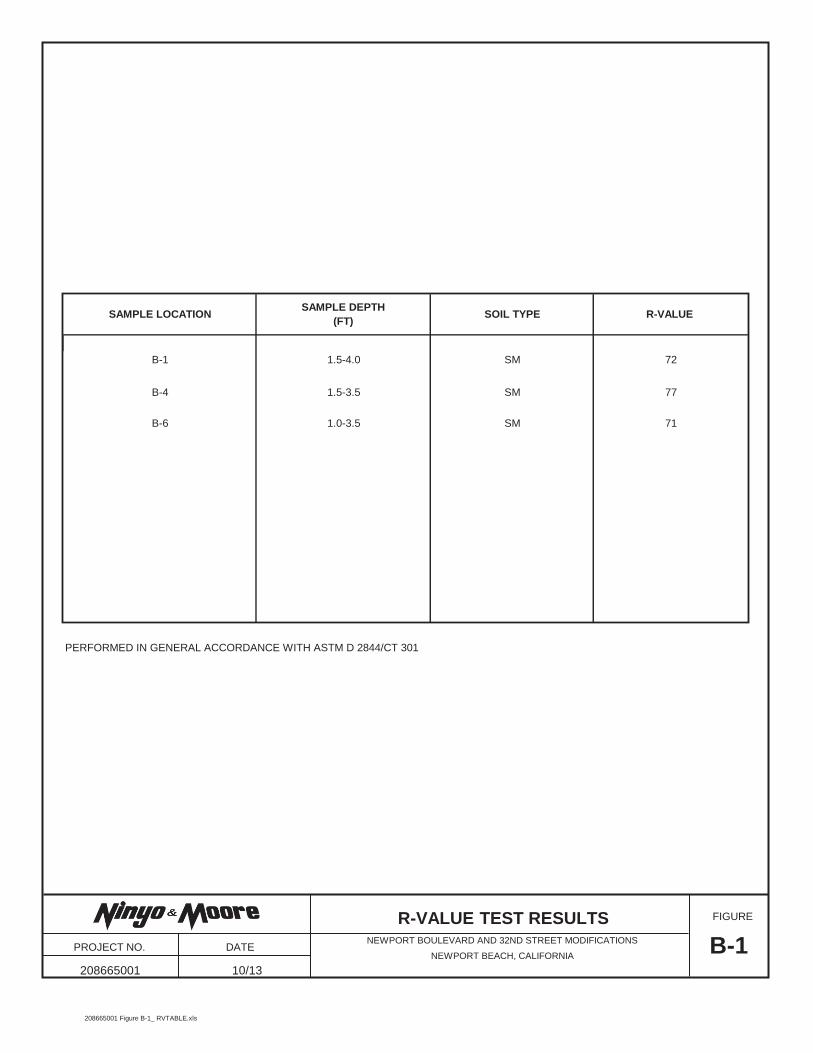
PERFORMED IN GENERAL ACCORDANCE WITH ASTM D 2844/CT 301
B-6
B-110/13208665001
NEWPORT BOULEVARD AND 32ND STREET MODIFICATIONS
NEWPORT BEACH, CALIFORNIA
SM
SM
SM
72
77
B-1
B-4
1.5-4.0
1.5-3.5
71
SAMPLE LOCATIONSAMPLE DEPTH
(FT)SOIL TYPE R-VALUE
1.0-3.5
R-VALUE TEST RESULTS PROJECT NO. DATE
FIGURE
208665001 Figure B-1_ RVTABLE.xls

1 PERFORMED IN GENERAL ACCORDANCE WITH CALIFORNIA TEST METHOD 6432 PERFORMED IN GENERAL ACCORDANCE WITH CALIFORNIA TEST METHOD 4173 PERFORMED IN GENERAL ACCORDANCE WITH CALIFORNIA TEST METHOD 422
208665001
80
260
5,505
1.0-3.5 2,390B-6
CHLORIDE
CONTENT 3
(ppm)pH 1
SAMPLE DEPTH (FT)
SAMPLE LOCATION (Ohm-cm)
RESISTIVITY 1 SULFATE CONTENT 2
(%)(ppm)
B-4 1.5-3.5 8.8
8.5
10/13B-2
NEWPORT BOULEVARD AND 32ND STREET MODIFICATIONS
NEWPORT BEACH, CALIFORNIA
0.003
40 0.004
25
CORROSIVITY TEST RESULTS
PROJECT NO. DATE
FIGURE
208665001 Figure B-2_CORROSIVITY B-4----B-6.xls