investigating the efficiency of energy transfer in
TRANSCRIPT

Bard College Bard College
Bard Digital Commons Bard Digital Commons
Senior Projects Spring 2021 Bard Undergraduate Senior Projects
Spring 2021
Investigating the Efficiency of Energy Transfer in Vehicular Motion Investigating the Efficiency of Energy Transfer in Vehicular Motion
Joshua M. Etukudo Bard College, [email protected]
Follow this and additional works at: https://digitalcommons.bard.edu/senproj_s2021
Part of the Automotive Engineering Commons, and the Physics Commons
This work is licensed under a Creative Commons Attribution-Noncommercial-No Derivative Works 4.0 License.
Recommended Citation Recommended Citation Etukudo, Joshua M., "Investigating the Efficiency of Energy Transfer in Vehicular Motion" (2021). Senior Projects Spring 2021. 212. https://digitalcommons.bard.edu/senproj_s2021/212
This Open Access is brought to you for free and open access by the Bard Undergraduate Senior Projects at Bard Digital Commons. It has been accepted for inclusion in Senior Projects Spring 2021 by an authorized administrator of Bard Digital Commons. For more information, please contact [email protected].
Investigating the Efficiency of Energy Transfer in Vehicular Motion
Senior Project Submitted to
The Division of Science, Math, and Computing
of Bard College
by
Joshua Etukudo
Annandale-on-Hudson, New York
May 2021


I would like to dedicate this project to my father and mother who have made great sacrifices to
enable me to pursue my studies in the U.S.


Acknowledgements
I would like to thank God, as well as my family and friends who have all provided support when
needed. I would like to thank Dr. Paul Cadden-Zimansky for his advice and availability
throughout the course of the project and the driver, Bruno Becher, for his stellar contributions.


Preface
One of my principal interests in life is transportation which involves building and working with
vehicles, and that is why I chose to pursue this project. This write-up, in addition to being a
small-scale study of the various properties of automobiles, is to serve as a guide for others who
wish to pursue such an endeavor in the years to come. To do this, I first take a look at three of the
many key structures which enable vehicular movement: The engine, the wheels and the steering
system. After this, I give a detailed recount of how I built the vehicle used in this project with
efficiency tips littered throughout the section. Then, I briefly explain the turn radius test and
maximum velocity and acceleration tests carried out while presenting and analyzing the data. In
all, this project investigates the dynamic motion of vehicles both in a straight line and in curves
and attempts to use the data gathered to establish a basic understanding of the efficiency of
energy transfer in vehicular motion.

Table of Contents
1 OVERVIEW .................................................................................................................................................... 1
1.1 CHOICE OF FRAMING MATERIAL ......................................................................................................................... 1 1.2 BASIC DESIGN ................................................................................................................................................. 2 1.3 MAKING CUTS ................................................................................................................................................ 3 1.4 DRILLING AND ASSEMBLY .................................................................................................................................. 3 1.5 OTHER CONSIDERATIONS .................................................................................................................................. 4 1.6 SAFETY GUIDELINES AND GOOD WORK HABITS ..................................................................................................... 5
2 BACKGROUND .............................................................................................................................................. 6
2.1 ENGINE OPERATION ......................................................................................................................................... 6 2.2 WHEEL VELOCITIES .......................................................................................................................................... 8 2.3 STEERING ....................................................................................................................................................... 9
3 ASSEMBLY .................................................................................................................................................. 13
3.1 THE FRAME .................................................................................................................................................. 13 3.2 THE WHEELS ................................................................................................................................................ 15 3.3 THE ENGINE AND DRIVE WHEEL ALIGNMENT ...................................................................................................... 17 3.4 THE BACKREST .............................................................................................................................................. 21 3.5 THE HANDLEBARS .......................................................................................................................................... 22 3.6 THE BRAKE ................................................................................................................................................... 24 3.7 MOUNTING THE ENGINE ................................................................................................................................. 26 3.8 CONNECTING THE THROTTLE CABLE .................................................................................................................. 27 3.9 WIRING THE KILL SWITCH ................................................................................................................................ 28
4 EXPERIMENTAL RESULTS AND ANALYSIS .................................................................................................... 30
4.1 DETERMINING THE TURN RADIUS ..................................................................................................................... 30 4.2 RESULTS ...................................................................................................................................................... 33 4.3 CALCULATING THE EXPECTED MAXIMUM VELOCITY OF THE GO-KART ....................................................................... 34 4.4 RESULTS ...................................................................................................................................................... 36
5 SUMMARY .................................................................................................................................................. 49
6 POSSIBLE MODIFICATIONS.......................................................................................................................... 50
6.1 STEERING MODIFICATIONS .............................................................................................................................. 50 6.2 MINIMIZING FLEXING OF THE WOODEN FRAME ................................................................................................... 51
APPENDIX A – WOOD CUTOUTS .......................................................................................................................... 52
APPENDIX B – OTHER IMPORTANT DATA & CALCULATIONS ................................................................................ 54
APPENDIX C – PARTS LIST .................................................................................................................................... 56
BIBLIOGRAPHY ..................................................................................................................................................... 57


1 Overview
1.1 Choice of Framing Material
In building any sort of vehicle, the framing material most often used is some kind of
steel/aluminum alloy which makes it reasonably sturdy while remaining light and nimble. Go-
karts are no different as you’ll find that most designs incorporate these materials for framing as
well. However, while metal frames are ideal (especially for more complex designs), using steel
requires a strong background in metalworking, which most do not have. Furthermore, the cost of
building a go-kart frame out of metal is higher than if done with other materials, and, for this
reason, I opted to build the kart out of wood.
2
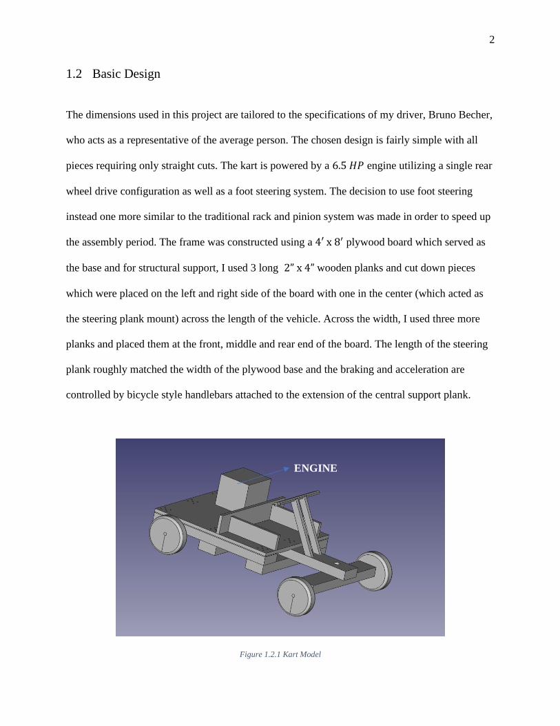
1.2 Basic Design
The dimensions used in this project are tailored to the specifications of my driver, Bruno Becher,
who acts as a representative of the average person. The chosen design is fairly simple with all
pieces requiring only straight cuts. The kart is powered by a 6.5 𝐻𝑃 engine utilizing a single rear
wheel drive configuration as well as a foot steering system. The decision to use foot steering
instead one more similar to the traditional rack and pinion system was made in order to speed up
the assembly period. The frame was constructed using a 4′ x 8′ plywood board which served as
the base and for structural support, I used 3 long 2” x 4” wooden planks and cut down pieces
which were placed on the left and right side of the board with one in the center (which acted as
the steering plank mount) across the length of the vehicle. Across the width, I used three more
planks and placed them at the front, middle and rear end of the board. The length of the steering
plank roughly matched the width of the plywood base and the braking and acceleration are
controlled by bicycle style handlebars attached to the extension of the central support plank.
Figure 1.2.1 Kart Model
ENGINE

3
1.3 Making Cuts
The tool I used most when making cuts was a hand-held circular saw because of the increased
controllability and precision it has over the common hacksaw. However, if one isn’t too worried
about aesthetics or the added physical labor involved, all the cutting in this project can be done
with a hacksaw. The process of making cuts with the circular saw involved the use of a guide
which, due to the extension of the plate, was offset to ensure the cut was being made at the right
location. Any straightedge can be used for this as long as its length is sufficient to guide the cut
in its entirety, as it would need to be clamped down; for most cuts, I found that a meter rule was
sufficient. However, for another part of the project - which involved cutting galvanized steel into
smaller chunks - I used a band saw but a hacksaw could also be used here.
1.4 Drilling and Assembly
For the assembly of all pieces, I used a power drill. Power drills are useful because they offer a
quick and efficient way to create lead holes as well as tighten screws into the wood with a hex
shank screwdriver bit. The drill is especially useful when attaching the planks to the board using
the 3 ½” deck screws and drilling holes in the wood to attach the wheels, engine and steering
plank.

4
1.5 Other Considerations
For this model, the use of foot steering leads to an interesting issue that has to be considered
carefully to ensure the safety of the operator. First and foremost, turning doesn’t occur in the
traditional way, where both wheels are locked into position and turned relative to some fixed axis
with the turn angle of the inside tire being greater than that of the outside tire. Instead, the axis
itself is rotated with both tires being turned at the same rate and angle. The main issue that arises
from this is the need for driver’s legs to travel through large arcs to make turns which could lead
to oversteering. The risk of oversteering is further accentuated by the fact that the front wheels
do not individually have a pivot point but, rather, there is a bolt in the center of the steering plank
which acts as the pivot for both wheels. Due to this, the wheels have to remain fixed to the plank
to provide a steady and sensible steering system, but that means there won’t be restoring (self-
aligning) torque applied to them while turning.
Furthermore, this affixation of the wheels to the plank in conjunction with the fact that it
is steered by foot, increases the mechanism’s overall sensitivity to surface variations on either
wheel. Sometimes, drivers may find that the steering plank wobbles forward and backward
during acceleration on textured/uneven surfaces due to imbalances as the wheels attempt to
create enough traction to launch the car forward. However, these issues are only truly serious at
very high speeds and with a 6.5 HP engine, I’m confident that by exercising caution and ensuring
the driver adheres to safe driving practices, the issues wouldn’t be a hassle. Nonetheless – to
lessen any risk – the kart would only be driven in straight lines at its higher speeds, while the
maximum velocity and acceleration tests are being conducted.
5
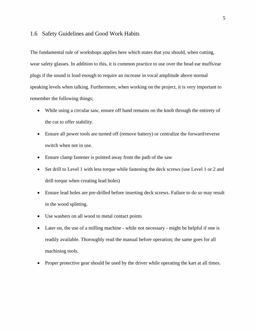
1.6 Safety Guidelines and Good Work Habits
The fundamental rule of workshops applies here which states that you should, when cutting,
wear safety glasses. In addition to this, it is common practice to use over the head ear muffs/ear
plugs if the sound is loud enough to require an increase in vocal amplitude above normal
speaking levels when talking. Furthermore, when working on the project, it is very important to
remember the following things;
• While using a circular saw, ensure off hand remains on the knob through the entirety of
the cut to offer stability.
• Ensure all power tools are turned off (remove battery) or centralize the forward/reverse
switch when not in use.
• Ensure clamp fastener is pointed away from the path of the saw
• Set drill to Level 1 with less torque while fastening the deck screws (use Level 1 or 2 and
drill torque when creating lead holes)
• Ensure lead holes are pre-drilled before inserting deck screws. Failure to do so may result
in the wood splitting.
• Use washers on all wood to metal contact points
• Later on, the use of a milling machine - while not necessary - might be helpful if one is
readily available. Thoroughly read the manual before operation; the same goes for all
machining tools.
• Proper protective gear should be used by the driver while operating the kart at all times.

6
2 Background
This section gives a brief explanation of some of the processes which permit vehicular motion.
Specifically, it highlights the physics behind steering, the rotational dynamics of the wheel to
provide motion and a brief description of how the engine converts chemical to kinetic energy. In
essentially all key areas, the systems utilized on the go-kart differ from those used in traditional
automobiles. So, it is only appropriate to provide a description of the way these key components
work.
2.1 Engine Operation
As stated earlier, the engine used is a 6.5 𝐻𝑃 (212𝑐𝑐) OHV (Overhead valve) horizontal shaft
gasoline engine. It is an internal combustion engine which, like all other gasoline or diesel-
powered engines, ignites the fuel which exerts pressure on and drives a piston that elicits the
change from chemical to kinetic energy. This engine in particular is a recoil-start, 4-stroke
engine and at a basic level, it operates like any other engine fitted in commercial vehicles with
7
the exception of its method of starting. In short, pulling on the rope causes the tensioning of a
spring which is connected to the crankshaft and is simply a means of getting it to revolve.
However, in key/button starter vehicles, this same effect is achieved through the activation of a
motor.
The process of converting fuel into energy for continual rotation/motion in a process
known as the engine cycle, is more interesting and is likely the most important design feature of
the IC engine. A 4-stroke engine, like the one I use, consists of a piston that completes 4 distinct
strokes. The first is known as the intake stroke where an air and fuel mixture is let into the
combustion chamber. The second is the compression stroke where the piston pushes up against
and compresses the newly introduced mixture. Succeeding this, there is an ignition event where
an electrical current is sent through the spark plug and it ignites the mixture which causes a
release of heat and the subsequent pressure – a result of this heat – forces the piston down in
what is known as the power stroke. Then via a connecting rod, the piston exerts a torque on the
shaft and causes it to rotate (the clutch is attached to the shaft on this engine). The fourth and
final stroke is the exhaust stroke in which the toxic waste gases produced are released from the
chamber via a valve or pipe.

8
2.2 Wheel Velocities
Each wheel of a vehicle in motion exhibits two types of velocities namely; angular and
translational with the relation being that the rotation of the wheels causes the forward or
backward motion of the vehicle. The equation that relates these two quantities is;
�⃑� 𝑇 = �⃑⃑� 𝑟 [2.1]
Where, �⃑� 𝑇, is the translational velocity in 𝑚
𝑠 and, �⃑⃑� , is the formal notation for the angular
velocity of a moving body in 𝑟𝑎𝑑
𝑠. Equation 2.1 simply states that the translational velocity of the
wheel is equal to the product of the wheel’s angular velocity and radius. Another thing worth
noting here is how these velocities add or subtract based on the point of observation on the
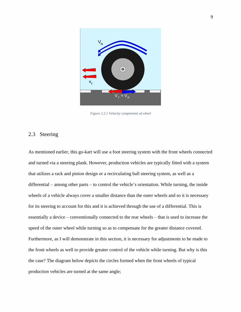
wheel. At the very top of the wheel, the vectors, 𝑉𝑇⃑⃑⃑⃑ and �⃑⃑� , are pointing in the same direction
and from our knowledge of vectors, this means the quantities add up directly. Furthermore, recall
from 𝑒𝑞𝑢𝑎𝑡𝑖𝑜𝑛 2.1 above, that 𝑉𝑇⃑⃑⃑⃑ = �⃑⃑� 𝑟 and so,
�⃑� 𝑡𝑜𝑝 = �⃑⃑� 𝑟 + �⃑⃑� 𝑟 = 2�⃑⃑� 𝑟 [2.2]
⇒ �⃑� 𝑡𝑜𝑝 = 2𝑉𝑇⃑⃑⃑⃑ [2.3]
And at the very bottom (point of contact between the wheel and the ground), 𝑉𝑇⃑⃑⃑⃑ and �⃑⃑� are equal
and opposite so they cancel out and the net velocity is zero. Figure 2.2.1 below gives a visual
representation of this.
⇒ �⃑� 𝑇 = �⃑⃑� [2.4]
9
Figure 2.2.1 Velocity components of wheel
2.3 Steering
As mentioned earlier, this go-kart will use a foot steering system with the front wheels connected
and turned via a steering plank. However, production vehicles are typically fitted with a system
that utilizes a rack and pinion design or a recirculating ball steering system, as well as a
differential – among other parts – to control the vehicle’s orientation. While turning, the inside
wheels of a vehicle always cover a smaller distance than the outer wheels and so it is necessary
for its steering to account for this and it is achieved through the use of a differential. This is
essentially a device – conventionally connected to the rear wheels – that is used to increase the
speed of the outer wheel while turning so as to compensate for the greater distance covered.
Furthermore, as I will demonstrate in this section, it is necessary for adjustments to be made to
the front wheels as well to provide greater control of the vehicle while turning. But why is this
the case? The diagram below depicts the circles formed when the front wheels of typical
production vehicles are turned at the same angle;

10
Figure 2.3.1 Vehicle steered with 1:1 ratio
As we see from the diagram, wheels turned at the same angle i.e. 1:1 ratio, would result in
differing centers of rotation and because of this, the circles formed by the inner and outer wheel
would intersect. This is a sign that sideslip would occur (especially at high speeds) as the inner or
outer wheel, given its fixed position in relation to the car and to the other wheel, would try to
correct for the intersection of the paths and force the car to traverse a more circular route thus, it
would slip or skid into its ideal position which could lead to fatal accidents. So, this means the
tires have to be turned at different angles to ensure the vehicle completes the turn smoothly and
this is achieved in most production vehicles via the use of Ackermann steering geometry. Which
is comprised of an inelastic bar called a tie-rod and a set of linkages to the steering arm that
offset the angle of the outer and inner wheel while turning so the inner wheel turns at a greater
angle than the outer wheel.
11
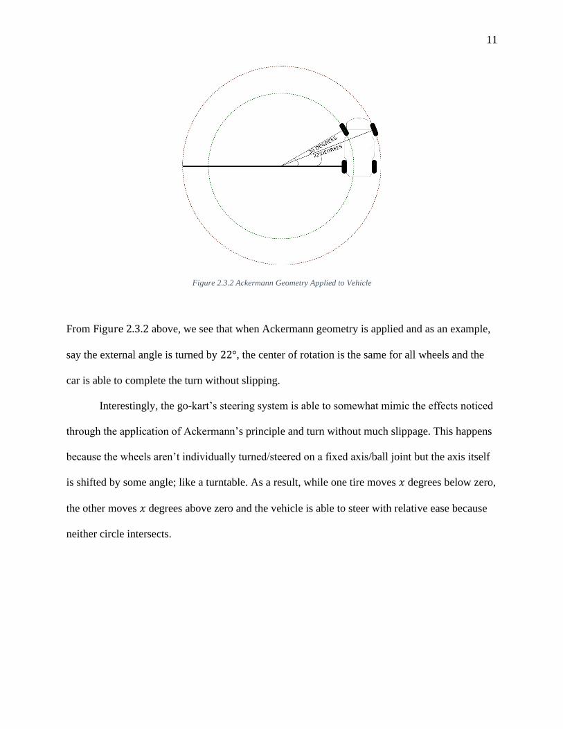
Figure 2.3.2 Ackermann Geometry Applied to Vehicle
From Figure 2.3.2 above, we see that when Ackermann geometry is applied and as an example,
say the external angle is turned by 22°, the center of rotation is the same for all wheels and the
car is able to complete the turn without slipping.
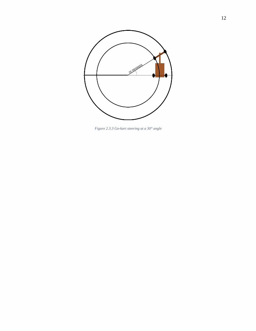
Interestingly, the go-kart’s steering system is able to somewhat mimic the effects noticed
through the application of Ackermann’s principle and turn without much slippage. This happens
because the wheels aren’t individually turned/steered on a fixed axis/ball joint but the axis itself
is shifted by some angle; like a turntable. As a result, while one tire moves 𝑥 degrees below zero,
the other moves 𝑥 degrees above zero and the vehicle is able to steer with relative ease because
neither circle intersects.
12
Figure 2.3.3 Go-kart steering at a 30° angle

13
3 Assembly
3.1 The Frame
The process of constructing the frame of the kart started with cutting a 4’ x 8’ (𝐿) plywood board
into two equal 4’ x 4’ pieces. However, the board was later trimmed to a narrower 2’8”’ x 4’ base
per the request of the driver. The next step involved cutting two, 2” x 4” wooden planks to use as
the supports for the plywood board in order to minimize flexing. As stated earlier, they were
placed both across the width and along the length of the plywood board. Furthermore, the central
plank along the length of the kart is to be used as the steering mount; as a result, it should extend
past the kart’s length. The length of this extension is based on the driver’s preference which was
obtained by simply asking them to sit on the plywood board with each leg on either side of the
central plank and simulate steering the kart (this should be done with a mock steering plank
placed on the mount with the bottom of their feet lightly resting on the edge of the plank directly
facing them). For Bruno, we found that his back, when in a seated position on the board was
14
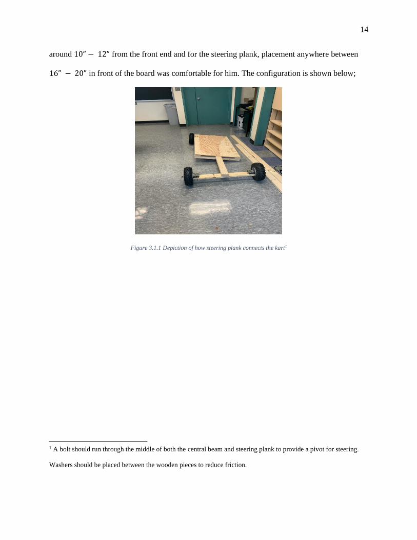
around 10” − 12” from the front end and for the steering plank, placement anywhere between
16” − 20” in front of the board was comfortable for him. The configuration is shown below;
Figure 3.1.1 Depiction of how steering plank connects the kart1
1 A bolt should run through the middle of both the central beam and steering plank to provide a pivot for steering.
Washers should be placed between the wooden pieces to reduce friction.

15
3.2 The Wheels
Mounting the wheels was done through the use of thin-walled square tubing, with holes pre-
machined or drilled after purchase, in order to securely fasten the wheels onto the wood. In this
case, I used galvanized steel rails and cut them into 8 sections – each with three holes – using a
bandsaw. The intent was to use two cutouts for each tire and instead of using one long axle to
connect the wheels on either side, I used partially threaded bolts to individually fasten each
wheel to the kart. This was done to eliminate the need for welding because threading allows for
the use of lock nuts to secure each wheel in place. Furthermore, partial threading was preferred
over full threading because there would be less friction and wear on the wheel bearings during
motion as the tires rotate on a smoother axis.
Figure 3.2.1 Wheel mounted onto the steering plank using galvanized steel rail.
The diameter of the holes in the galvanized steel rail was slightly bigger than 3/8” so it was
convenient to use this size bolt to fasten them to the board. Furthermore, the bolt that acts as the
axle for the wheel needs to be sturdy, so I used 5/8” diameter bolts. However, given that the
16
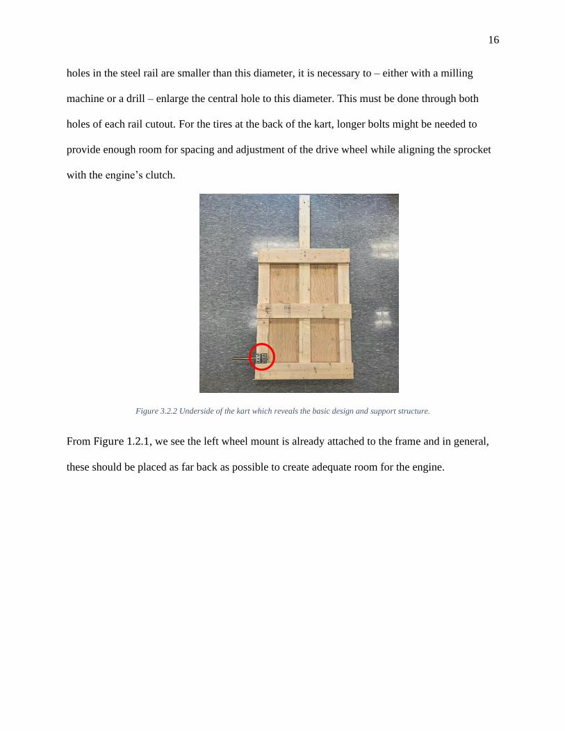
holes in the steel rail are smaller than this diameter, it is necessary to – either with a milling
machine or a drill – enlarge the central hole to this diameter. This must be done through both
holes of each rail cutout. For the tires at the back of the kart, longer bolts might be needed to
provide enough room for spacing and adjustment of the drive wheel while aligning the sprocket
with the engine’s clutch.
Figure 3.2.2 Underside of the kart which reveals the basic design and support structure.
From Figure 1.2.1, we see the left wheel mount is already attached to the frame and in general,
these should be placed as far back as possible to create adequate room for the engine.

17
3.3 The Engine and Drive Wheel Alignment
Once the rails are attached to the board with the wheel bolts passed through them, the logical
next step is to mount the engine. This was done by first of all placing the engine in the desired
orientation, with the shaft pointing out towards the drive wheel while ensuring that it extends a
reasonable distance past the edge of the kart. Then, the clutch should be fitted onto the shaft
using the lock and pins2 provided.
Afterwards, use a straightedge to make sure the teeth of the clutch and sprocket are
aligned3; with a pen or pencil, outline the engine’s frame on the kart and mark the fastening
points. Then using a power drill and a 5/16” bit, drill holes all the way through each point as
shown in Figure 3.3.1;
Figure 3.3.1 Engine’s outline with fastening holes marked and drilled.
2 An Allen wrench is needed to fasten the pins. 3 It is advisable to determine and carry out wheel spacing before this to improve accuracy. Another technique which
proved handy for alignment was – without the clutch pinned to the shaft – connecting the sprocket and clutch via the
chain and spinning the free drive wheel by hand until the clutch eventually settles in its aligned position.
18
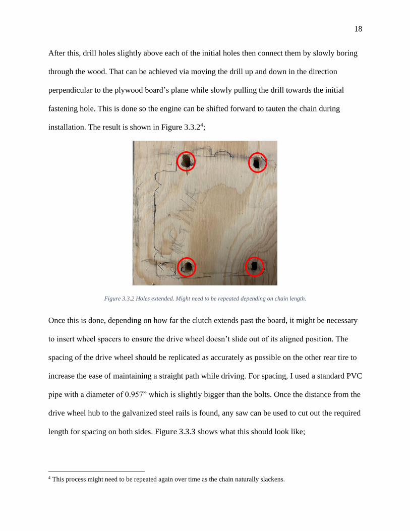
After this, drill holes slightly above each of the initial holes then connect them by slowly boring
through the wood. That can be achieved via moving the drill up and down in the direction
perpendicular to the plywood board’s plane while slowly pulling the drill towards the initial
fastening hole. This is done so the engine can be shifted forward to tauten the chain during
installation. The result is shown in Figure 3.3.24;
Figure 3.3.2 Holes extended. Might need to be repeated depending on chain length.
Once this is done, depending on how far the clutch extends past the board, it might be necessary
to insert wheel spacers to ensure the drive wheel doesn’t slide out of its aligned position. The
spacing of the drive wheel should be replicated as accurately as possible on the other rear tire to
increase the ease of maintaining a straight path while driving. For spacing, I used a standard PVC
pipe with a diameter of 0.957” which is slightly bigger than the bolts. Once the distance from the
drive wheel hub to the galvanized steel rails is found, any saw can be used to cut out the required
length for spacing on both sides. Figure 3.3.3 shows what this should look like;
4 This process might need to be repeated again over time as the chain naturally slackens.

19
Figure 3.3.3 PVC used for spacing on Right rear wheel
Note: washers could be an alternate means of providing spacing if one is able to stack a
sufficient number of them5.
Unlike the rest of the tires, the drive wheel is a special configuration which includes a sprocket
hub, sprocket and brake drum. This can be purchased pre-assembled, but due to the
unpredictability of its availability, it might be necessary to purchase the individual parts and
assemble by oneself. All parts can be purchased on the website stated in Appendix B – or from
other sources. Naturally, the drive wheel must be the same size as the other tires on the kart and
should ideally be purchased with the sprocket hub already attached to it. The assembly is
relatively straightforward as long as the sprocket used has a smaller6 diameter than the wheel
itself. The first step is to pass the bolts through the fastening points on the sprocket hub, then
align them with the holes on the sprocket itself and pass the bolts through (this is best achieved
5 Even if the distances don’t match the initial measurement, the position of the clutch can be adjusted easily to
restore alignment with the sprocket. 6 Approximately the same as the rims or the wheels inner diameter

20
with the wheel in its upright position to prevent the bolts from falling out). After this, pass the
bolts through the brake drum as well and partially secure the entire configuration using
locknuts7. Then lay the wheel on its side with the face of the sprocket pointing upwards and
screw in the nuts completely.
7 This is done to enable us to lay the wheel on its side and tighten each bolt individually without worry of the others
falling out.

21
3.4 The Backrest
The backrest was built using a 28” (𝐿) , 1 ½” x 12” plywood board and three 12” (𝐿),
2” x 4” planks as the supports. Assembling the seats is a relatively simple task; it was done by
attaching the three planks to the left edge, center and right edge of the board using deck screws,
then connecting it to the kart using corner brackets. In total, three braces were used to fasten the
backrest to the plywood base which has proven a sturdy setup thus far. As an added safety
feature, side rails/protectors were installed. This consisted of two 3 ½” x 18 ½” planks on either
edge of the plywood base.
Figure 3.4.1 Backrest fastened to the kart with 6-hole corner brackets
22
3.5 The Handlebars
The handlebars were purchased as a set at the website shown in Appendix C – Parts List and
contained the brake lever and throttle twist grip as well as the throttle and brake cables; the set
ships unassembled8. Simply loosen the strap mount, position the component as desired and
relink/tighten (not all the way initially so as to allow for final adjustments). Then, to find out the
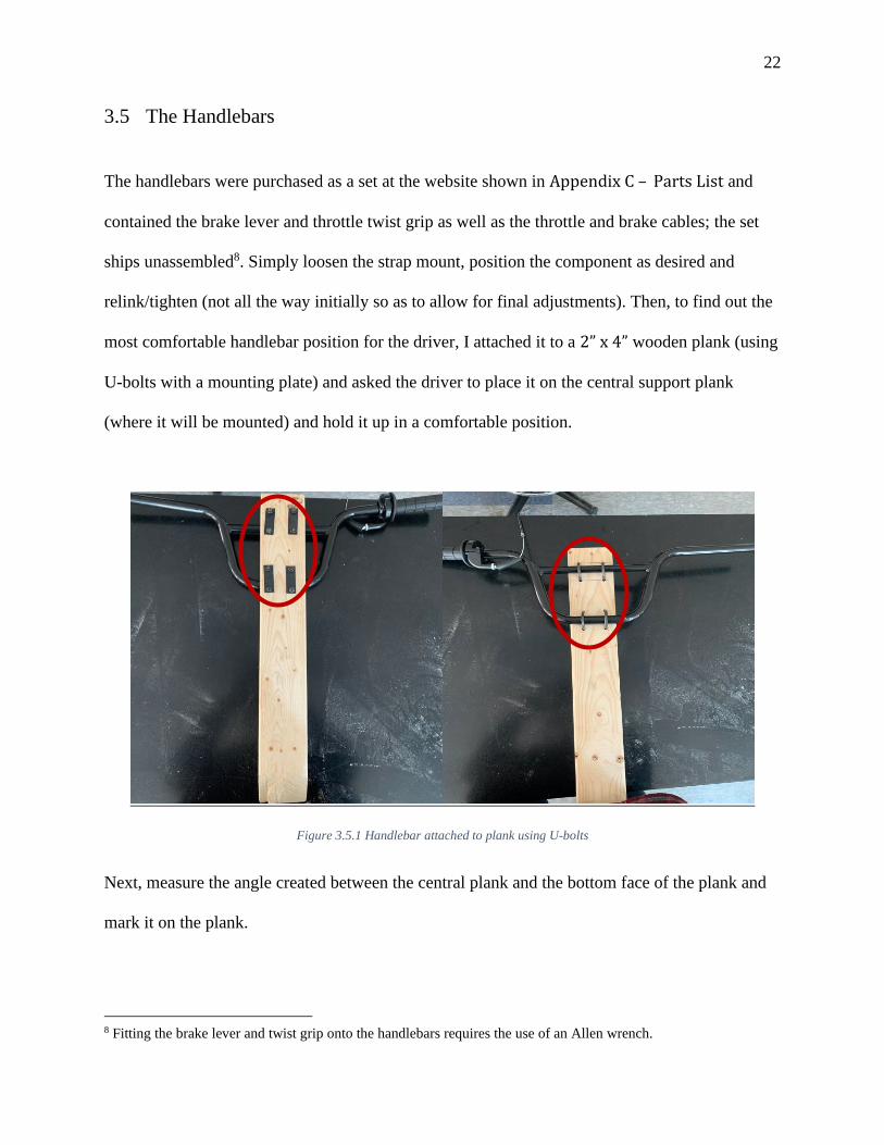
most comfortable handlebar position for the driver, I attached it to a 2” x 4” wooden plank (using
U-bolts with a mounting plate) and asked the driver to place it on the central support plank
(where it will be mounted) and hold it up in a comfortable position.
Figure 3.5.1 Handlebar attached to plank using U-bolts
Next, measure the angle created between the central plank and the bottom face of the plank and
mark it on the plank.
8 Fitting the brake lever and twist grip onto the handlebars requires the use of an Allen wrench.
23
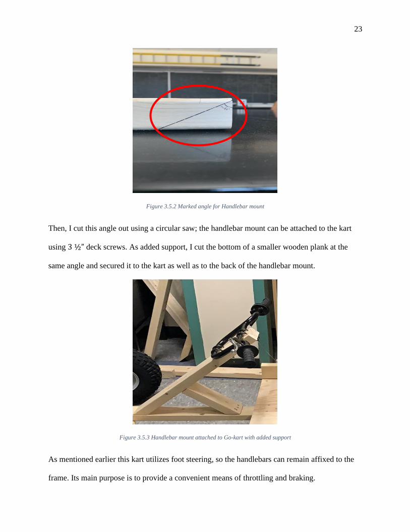
Figure 3.5.2 Marked angle for Handlebar mount
Then, I cut this angle out using a circular saw; the handlebar mount can be attached to the kart
using 3 ½” deck screws. As added support, I cut the bottom of a smaller wooden plank at the
same angle and secured it to the kart as well as to the back of the handlebar mount.
Figure 3.5.3 Handlebar mount attached to Go-kart with added support
As mentioned earlier this kart utilizes foot steering, so the handlebars can remain affixed to the
frame. Its main purpose is to provide a convenient means of throttling and braking.

24
3.6 The Brake
On this kart, the most convenient means of braking is through the use of a brake band mounted
around the drum on the drive wheel. Installation is fairly tricky as the band has to be set up in a
way so that, once the brake is engaged, it would cover enough of the drum and grip it tightly
enough to create adequate stopping/friction force to overcome the wheels rotation. Although, the
predator engine conveniently begins to automatically slow the kart down once the throttle is
disengaged, as the RPM of the shaft is contingent on how far the throttle lever is pulled away
from zero. Thus, once the throttle is returned to its idle position during motion, the kart slows
down. However, it is still important to have strong brakes to increase the overall controllability
of the kart and as an extra safety precaution for the driver. To do this I used, a 5/8” bolt which
was to be passed through a wooden block or something similar to act as an anchor point for the
band. I also used a few lock nuts (or at least one lock nut and a few regular ones) to keep the
band steady and fairly stationary. I started off by cutting out a wooden block and drilling a hole
straight9 through it at a height which ensured the top of the band was as close to the drum as
possible without actually touching it. I found that drilling the hole near the bottom of the block
worked best as shown in item K on Appendix A – Wood Cutouts.
The next step was to pass the bolt through one set of clips and mark out the spot on the
bolt that fell between each clip. A small10 hole was then drilled through the bolt at this point to
allow the brake cable to pass through. Once this was completed, I used lock nuts to secure the
brake band in place, passed the bolt through the wood and fastened it to the kart. Figure 3.6.1
shows what this should look like.
9 It is very important to drill straight through the wood 10 About 7/64”
25
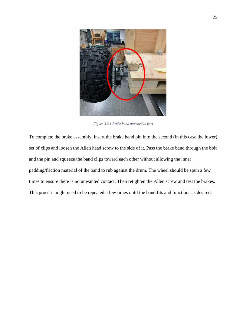
Figure 3.6.1 Brake band attached to kart
To complete the brake assembly, insert the brake band pin into the second (in this case the lower)
set of clips and loosen the Allen head screw to the side of it. Pass the brake band through the bolt
and the pin and squeeze the band clips toward each other without allowing the inner
padding/friction material of the band to rub against the drum. The wheel should be spun a few
times to ensure there is no unwanted contact. Then retighten the Allen screw and test the brakes.
This process might need to be repeated a few times until the band fits and functions as desired.
26
3.7 Mounting the Engine
Mounting the engine to the frame of the kart requires 4 bolts and locknuts. Depending on where
the engine is placed relative to the edge of the kart, it might be necessary to get two sets of bolts
with different lengths as one side of the engine might go through a support beam as well as the
plywood board and the other goes through just the plywood. Thus, longer bolts would be needed
on one side. I used two 4” and 2” (𝐿) fully threaded 5/16” screws to bolt the engine onto the
kart. However, I ended up having to cut the 4” bolt by about a ½” so the lock nuts could be
fastened.
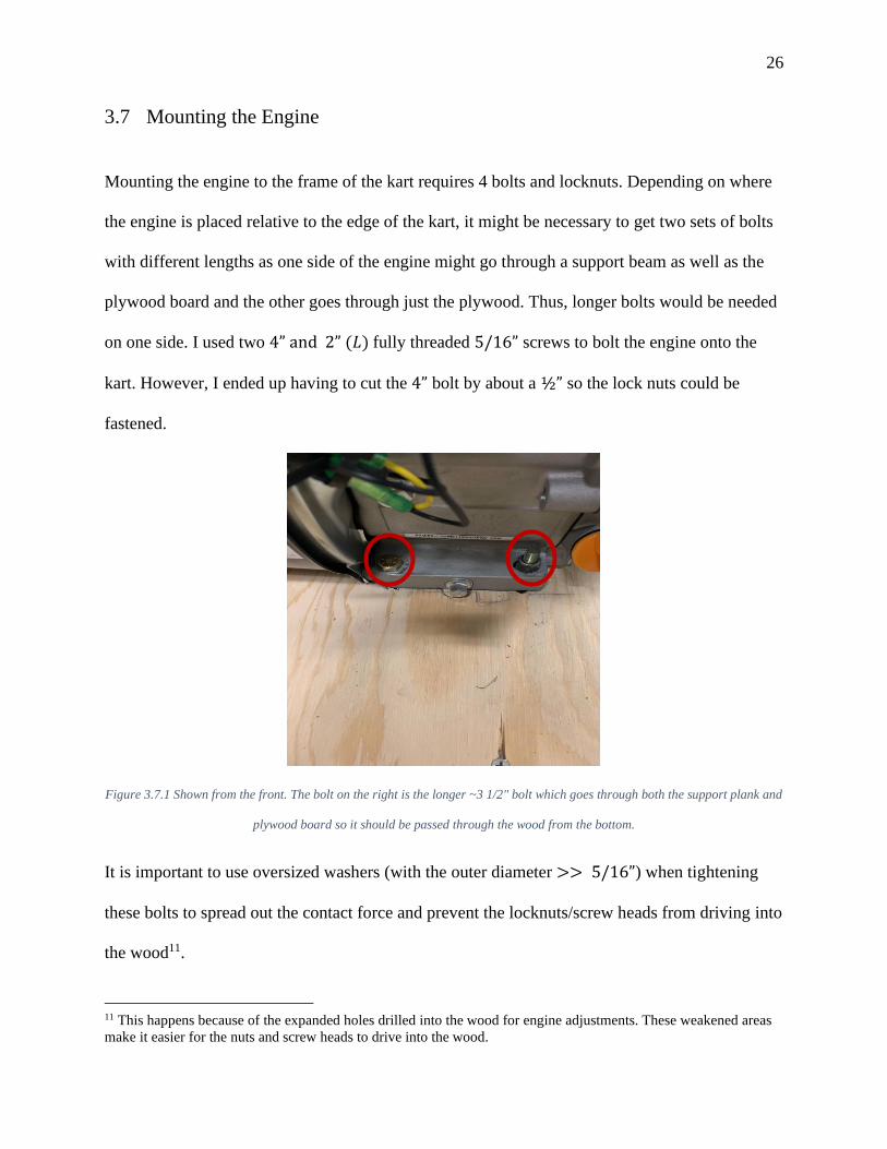
Figure 3.7.1 Shown from the front. The bolt on the right is the longer ~3 1/2" bolt which goes through both the support plank and
plywood board so it should be passed through the wood from the bottom.
It is important to use oversized washers (with the outer diameter >> 5/16”) when tightening
these bolts to spread out the contact force and prevent the locknuts/screw heads from driving into
the wood11.
11 This happens because of the expanded holes drilled into the wood for engine adjustments. These weakened areas
make it easier for the nuts and screw heads to drive into the wood.

27
3.8 Connecting the Throttle Cable
The throttle cable is connected to the engine via a lever located in the top center of the engine.
As shown in Figure 3.8.1, the cable is connected to the engine by partially unfastening the
screws on both the housing clamp and pinhole. Then, the cable should be passed through the
housing clamp to prevent unnecessary movement and the wire itself should be pulled through the
pinhole.
Figure 3.8.1 The blue rectangle is the lever; the green circle is the housing clamp and the red circle is where the hole is located.
Both screws should then be tightened. To ensure that the throttle always returns to the
disengaged position, I decided to add an extra spring which can be found at any local hardware
store and attached it to any suitable point that creates spring extension when the throttle is
engaged.
28
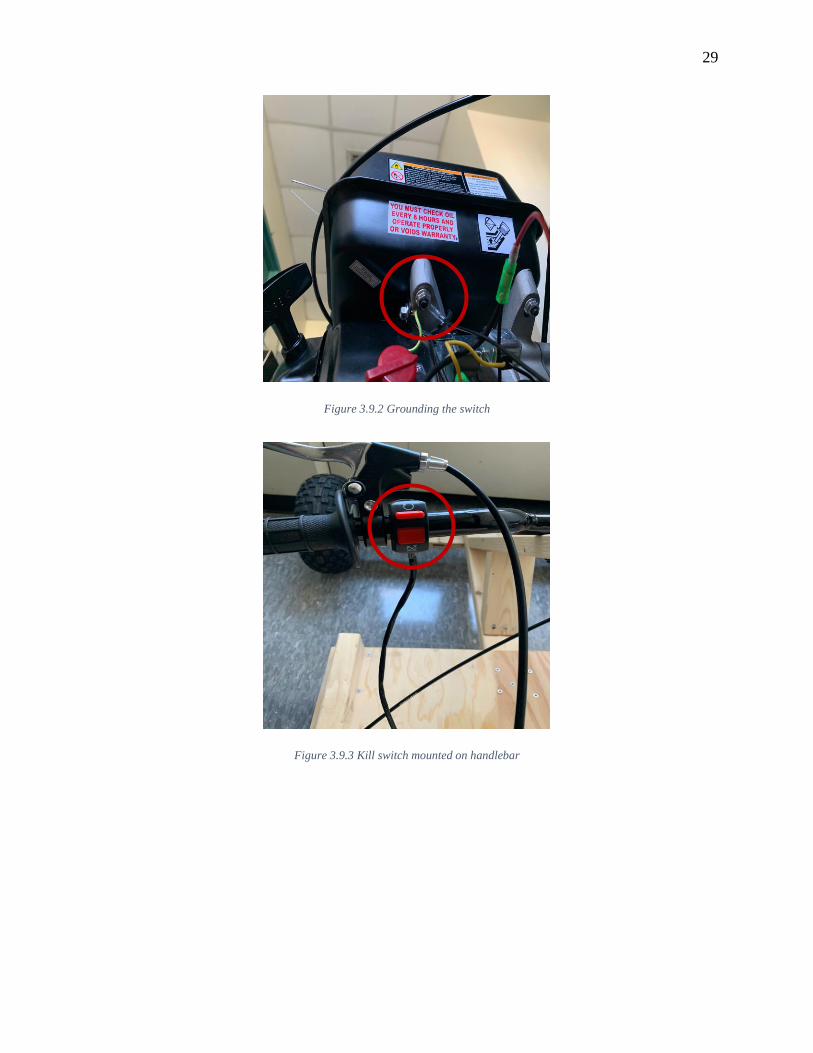
3.9 Wiring the Kill Switch
This is an optional additional feature but nonetheless, an important one. The kill switch is
mounted on the handlebar and gives drivers the ability to toggle the engine off from their seat in
emergency situations. The switch and wires ship with the handlebar as well. The switch is
attached to the handlebar in the same way as the brake lever and throttle twist grip; connecting
the switch is fairly easy. This is done by disconnecting the switch on the engine from the oil
sensor12 and plugging the kill switch from the handlebar into this (male to female connection) as
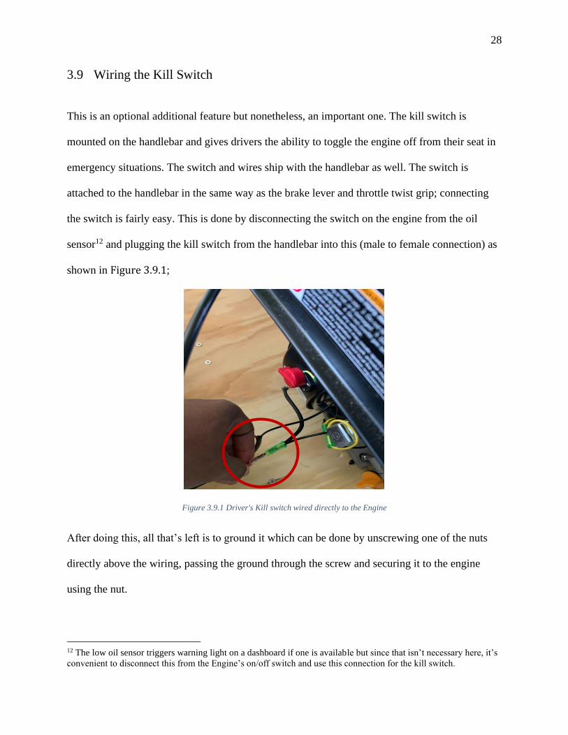
shown in Figure 3.9.1;
Figure 3.9.1 Driver's Kill switch wired directly to the Engine
After doing this, all that’s left is to ground it which can be done by unscrewing one of the nuts
directly above the wiring, passing the ground through the screw and securing it to the engine
using the nut.
12 The low oil sensor triggers warning light on a dashboard if one is available but since that isn’t necessary here, it’s
convenient to disconnect this from the Engine’s on/off switch and use this connection for the kill switch.
29
Figure 3.9.2 Grounding the switch
Figure 3.9.3 Kill switch mounted on handlebar

30
4 Experimental Results and Analysis
4.1 Determining the Turn Radius
From Figure 4.1.1, we see that it is possible to estimate what the outer wheel’s turn radius
should be, given a certain angle theta. The variable, 𝑟, represents this radius while, ℎ, is the
distance from the outer rear wheel axle to that of the front wheel i.e. center to center distance
between both wheels. Furthermore, 𝑥 represents the vertical distance travelled by the center if the
outer wheel when the steering plank is turned at a certain angle theta and is calculated by
multiplying the distance from the pivot to the tire, 𝑠, by the sine of the turning angle. So,
𝑥 = 𝑠 ∙ sin(𝜃) [4.1]

31
The triangle below shows this relationship;
Figure 4.1.1
Finally, the addition of the quantities, 𝑥 and ℎ effectively gives us the base of the right triangle
which can then be divided by the 𝑠𝑖𝑛𝑒 of the turn angle to yield the turn radius. Hence,
𝑟 = (ℎ + 𝑥)/𝑠𝑖𝑛(𝜃) [4.2]
Figure 4.1.2
This formula helps us to determine what the turn radius of the vehicle should be for any turn
angle, 𝜃.
𝑥
𝜃

32
To test this, I used the 𝐴𝑛𝑔𝑙𝑒 𝑀𝑒𝑡𝑒𝑟𝑇𝑀 app on the IOS App Store as a protractor by clamping
the phone to a stand, with the rear camera pointed to the ground, and aligning the top edge of the
steering plank to its zero axis then, I moved it to the desired angle. Figure 4.1.3 shows this;
Figure 4.1.3
To prevent any accidental movement of the steering plank during testing, I locked it in place by
tightening the nut below; this ensured the angle would remain constant throughout the
experiment. Finally, the driver was asked to slowly drive around in a circle and rocks were
placed at various points on the circle traced out by the outer wheel. The distance from one end of
the path to the other, through the center, was measured. This gives us the diameter of the circle
and the turn radius could then be found by dividing this diameter by two.

33
Figure 4.1.4 Measuring the diameter of half circle formed
4.2 Results
The table below shows the radius found �̂�, as well as the expected radius 𝑅 and the absolute
value of the relative error 𝛿𝑅;
Table 4.2.A
𝜽° �̂� (inches) 𝑹 (Inches) |𝜹𝑹| (%)
20 191 194.93 2.02
22 – 22.5 174
179.67 – 176.29 3.16 – 1.30
25 155.75
161.47 3.54
27 – 27.5 151.5
151.66 – 149.44 0.11 – 1.38
30 139.75 139.50 0.18
The relative error is calculated using the following formula;
|𝛿𝑅| = |�̂�−R
𝑅| [4.3]

34
4.3 Calculating the Expected Maximum velocity of the Go-Kart
The maximum velocity of the go-kart was computed through a fairly simple algorithm which did
not include any additive forces (traction/friction) or resistive forces (inertia and aerodynamic
drag) as a more precise estimate would. For this calculation, I only consider the gear ratio, 𝑅𝑃𝑀
of the engine and the diameter of the wheel. The steps are as follows,
First of all, find the circumference of the drive-wheel by measuring its diameter and multiplying
this by 𝑃𝑖 so,
𝐶𝑤 = 𝜋𝑑𝑤 [4.4]
However, it is possible to increase accuracy as this circumference neither accounts for the static
compression of the wheel when a mass is placed on it, nor does it factor in compression due to
the dynamic motion of the wheel. For this, we define new variables, 𝑑𝑤𝑠 and 𝑑𝑤𝑑, where 𝑑𝑤𝑠is
the static diameter and 𝑑𝑤𝑑 is the dynamic wheel diameter.
𝑑𝑤𝑠 = 0.95𝑑𝑤 [4.5]
𝑑𝑤𝑑 = 0.98𝑑𝑤𝑠 [4.6]
Which means the dynamic circumference can now be calculated;
𝐶𝑤𝑑 = 𝜋 × (0.98)(0.95)𝑑𝑤 [4.7]
𝐶𝑤𝑑 = 𝜋 × (0.931)𝑑𝑤 [4.8]
Equation 4.8 states that the circumference13 of the drive wheel in motion is the product of 0.931
times the free wheel diameter, 𝑑𝑤, and 𝑃𝑖.
13 The circumference should be expressed in feet (ft).

35
After this, we can compute the gear ratio by dividing the number of teeth on the sprocket
by the number of teeth on the clutch. This ratio allows us to determine the 𝑅𝑃𝑀 of the drive
wheel due to the rotation of the clutch. So,
𝐺𝑅 =
𝑆𝑝𝑟𝑜𝑐𝑘𝑒𝑡 𝑡𝑒𝑒𝑡ℎ #
𝐶𝑙𝑢𝑡𝑐ℎ 𝑡𝑒𝑒𝑡ℎ # [4.9]
Then using this value, we can find the wheel’s RPM by dividing the maximum RPM of the
engine by the gear ratio calculated above,
𝑤𝑅𝑃𝑀 =
𝑒𝑅𝑃𝑀
𝐺𝑅 [4.10]
With this information, we can now compute the maximum translational velocity of the kart by
multiplying the circumference of the wheel by the wheel’s RPM;
�⃑� 𝑚𝑎𝑥 (𝑓𝑡
𝑚𝑖𝑛⁄ ) = 𝐶𝑤 ∙ 𝑤𝑅𝑃𝑀 [4.11]
The result of this is the maximum velocity in 𝑓𝑡
𝑚𝑖𝑛, which can be changed to 𝑚𝑝ℎ by the
following conversion;
1(
𝑓𝑡
𝑚𝑖𝑛) =
1
88 (𝑚𝑝ℎ) [4.12]
The data required to compute this is shown on Table B 2 in
Appendix B – Other Important Data & Calculations.
Using that information, I found that the maximum achievable velocity of the kart is about
24.09 𝑚𝑝ℎ. The goal for this test is to be able to reach 20 𝑚𝑝ℎ.

36
4.4 Results
The velocity of the kart was found through utilizing the video analysis capabilities of a program
called PASCO Capstone. It is able to compute the velocity of a moving object through an
automatic or manual tracking tool built into it. The first step is to select and input the length of
the distance covered via the scaling tool to give the program a sense of the scale. I utilized the
manual tracking tool as I found that it led to more consistent results. The distance covered was
determined by measuring the lengths of the 15 parking spots covered in the video. This was
found to be roughly 42.28 𝑚.
Then, the frame increment/advancement rate (number of frames advanced after each
tracking point has been placed) should be set. I tested the results with a frame
increment/advancement rate (FAR), of 5 frames which corresponds to a 0.166 𝑠 interval between
each point. As each tracking point is placed, the program determines the velocity and
acceleration by computing �⃑� 𝑇 as the distance travelled divided by the time taken and 𝑎 𝑇 as the
change in velocity over the time interval. However, the acceleration data collected by the
program was quite erratic for some unknown reason, so I opted to calculate this myself using the
velocity and time data provided.
�⃑� 𝑇 =
𝐷
𝑡 [4.13]
𝑎 𝑇 =
∆�⃑�
𝑡 [4.14]
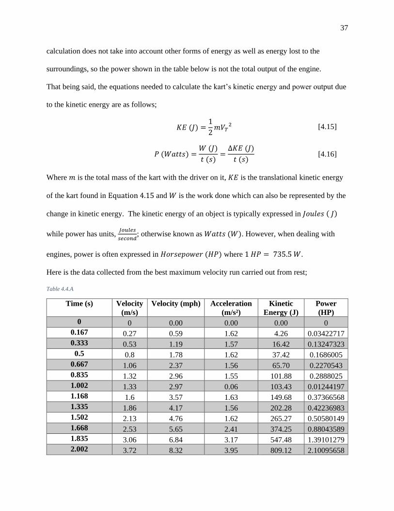
Furthermore, the data (specifically the kart’s velocity) can be used to calculate the kinetic energy
of the go-kart and subsequently the power consumed. However, it is important to note that this
37
calculation does not take into account other forms of energy as well as energy lost to the
surroundings, so the power shown in the table below is not the total output of the engine.
That being said, the equations needed to calculate the kart’s kinetic energy and power output due
to the kinetic energy are as follows;
𝐾𝐸 (𝐽) =
1
2𝑚𝑉𝑇
2 [4.15]
𝑃 (𝑊𝑎𝑡𝑡𝑠) =
𝑊 (𝐽)
𝑡 (𝑠)=
∆𝐾𝐸 (𝐽)
𝑡 (𝑠) [4.16]
Where 𝑚 is the total mass of the kart with the driver on it, 𝐾𝐸 is the translational kinetic energy
of the kart found in Equation 4.15 and 𝑊 is the work done which can also be represented by the
change in kinetic energy. The kinetic energy of an object is typically expressed in 𝐽𝑜𝑢𝑙𝑒𝑠 ( 𝐽)
while power has units, 𝐽𝑜𝑢𝑙𝑒𝑠
𝑠𝑒𝑐𝑜𝑛𝑑; otherwise known as 𝑊𝑎𝑡𝑡𝑠 (𝑊). However, when dealing with
engines, power is often expressed in 𝐻𝑜𝑟𝑠𝑒𝑝𝑜𝑤𝑒𝑟 (𝐻𝑃) where 1 𝐻𝑃 = 735.5 𝑊.
Here is the data collected from the best maximum velocity run carried out from rest;
Table 4.4.A
Time (s) Velocity
(m/s)
Velocity (mph) Acceleration
(m/s²)
Kinetic
Energy (J)
Power
(HP)
0 0 0.00 0.00 0.00 0
0.167 0.27 0.59 1.62 4.26 0.03422717
0.333 0.53 1.19 1.57 16.42 0.13247323
0.5 0.8 1.78 1.62 37.42 0.1686005
0.667 1.06 2.37 1.56 65.70 0.2270543
0.835 1.32 2.96 1.55 101.88 0.2888025
1.002 1.33 2.97 0.06 103.43 0.01244197
1.168 1.6 3.57 1.63 149.68 0.37366568
1.335 1.86 4.17 1.56 202.28 0.42236983
1.502 2.13 4.76 1.62 265.27 0.50580149
1.668 2.53 5.65 2.41 374.25 0.88043589
1.835 3.06 6.84 3.17 547.48 1.39101279
2.002 3.72 8.32 3.95 809.12 2.10095658
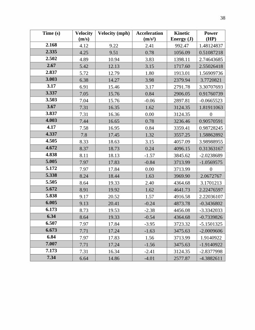
38
Time (s) Velocity
(m/s)
Velocity (mph) Acceleration
(m/s²)
Kinetic
Energy (J)
Power
(HP)
2.168 4.12 9.22 2.41 992.47 1.48124837
2.335 4.25 9.51 0.78 1056.09 0.51087218
2.502 4.89 10.94 3.83 1398.11 2.74643685
2.67 5.42 12.13 3.15 1717.60 2.55026418
2.837 5.72 12.79 1.80 1913.01 1.56909736
3.003 6.38 14.27 3.98 2379.94 3.7720821
3.17 6.91 15.46 3.17 2791.78 3.30707693
3.337 7.05 15.76 0.84 2906.05 0.91760739
3.503 7.04 15.76 -0.06 2897.81 -0.0665523
3.67 7.31 16.35 1.62 3124.35 1.81911063
3.837 7.31 16.36 0.00 3124.35 0
4.003 7.44 16.65 0.78 3236.46 0.90570591
4.17 7.58 16.95 0.84 3359.41 0.98728245
4.337 7.8 17.45 1.32 3557.25 1.58862892
4.505 8.33 18.63 3.15 4057.09 3.98988955
4.672 8.37 18.73 0.24 4096.15 0.31363167
4.838 8.11 18.13 -1.57 3845.62 -2.0238689
5.005 7.97 17.83 -0.84 3713.99 -1.0569575
5.172 7.97 17.84 0.00 3713.99 0
5.338 8.24 18.44 1.63 3969.90 2.0672767
5.505 8.64 19.33 2.40 4364.68 3.1701213
5.672 8.91 19.92 1.62 4641.73 2.22476597
5.838 9.17 20.52 1.57 4916.58 2.22036107
6.005 9.13 20.41 -0.24 4873.78 -0.3436802
6.173 8.73 19.53 -2.38 4456.08 -3.3342033
6.34 8.64 19.33 -0.54 4364.68 -0.7339826
6.507 7.97 17.84 -3.95 3723.32 -5.1501325
6.673 7.71 17.24 -1.63 3475.63 -2.0009606
6.84 7.97 17.83 1.56 3713.99 1.9140922
7.007 7.71 17.24 -1.56 3475.63 -1.9140922
7.173 7.31 16.34 -2.41 3124.35 -2.8377998
7.34 6.64 14.86 -4.01 2577.87 -4.3882611

39
Chart 4.4.I
The chart above shows the kart’s velocity in the 𝑥 direction versus time. From the data presented,
we see that the kart is able to reach a maximum velocity of 20.52 𝑚𝑝ℎ at the 5.838 𝑠 mark
which is about 85.2% of the maximum speed attainable. This result means the goal of reaching
20 𝑚𝑝ℎ was achieved. For this run, the driver started from rest and accelerated at full throttle
with the intention to continue accelerating over the distance of 42.278.𝑚 specified above14. The
data shown roughly resembles the expected profile of the velocity versus time graph of a vehicle
starting from rest. The acceleration is, on average, highest during the first few seconds until the
velocity slowly plateaus once the maximum speed is reached and we can see that on the graph.
14 The distance covered was merely a function of the number of consecutive free parking spots available that could
fit within the frame of the video

40
However, we also see that the kart actually slows down towards the end of the run and this
would have contributed to the result being 14.8% less than the maximum velocity achievable, as
the distance covered was probably not sufficient to allow the kart to reach its peak velocity15.
Nonetheless, we can gain a sense of the feasibility of the data by performing a rough
calculation of the velocity through our own frame by frame analysis of the video. iPhone videos
are shot at 30 𝑓𝑝𝑠 so, by using the distance covered, the number of frames taken to cover this
distance and the aforementioned 30 𝑓𝑝𝑠, we can find the velocity at each interval as follows;
𝑡 (𝑠) =
𝑁𝑢𝑚𝑏𝑒𝑟 𝑜𝑓 𝐹𝑟𝑎𝑚𝑒𝑠 𝑓𝑜𝑟 𝑠𝑝𝑜𝑡 (𝐹)
𝐹𝑟𝑎𝑚𝑒𝑠 𝑝𝑒𝑟 𝑠𝑒𝑐𝑜𝑛𝑑 (𝐹𝑠)
[4.17]
�⃑� (
𝑚
𝑠) =
𝐷𝑖𝑠𝑡𝑎𝑛𝑐𝑒 𝑝𝑒𝑟 𝑠𝑝𝑜𝑡 (𝑚)
𝑡 (𝑠)
[4.18]
15 Slowing down was necessary to prevent the driver from running into cars parked at the other side of the lot.
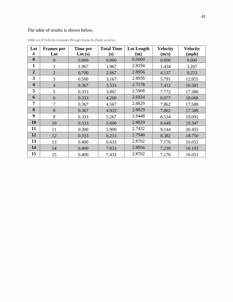
41
The table of results is shown below,
Table 4.4.B Velocity estimates through frame-by-frame analysis
Lot
#
Frames per
Lot
Time per
Lot (s)
Total Time
(s)
Lot Length
(m)
Velocity
(m/s)
Velocity
(mph)
0 0 0.000 0.000 0.0000 0.000 0.000
1 1 1.967 1.967 2.8194 1.434 3.207
2 2 0.700 2.667 2.8956 4.137 9.253
3 3 0.500 3.167 2.8956 5.791 12.955
4 4 0.367 3.533 2.7178 7.412 16.581
5 5 0.333 3.867 2.5908 7.772 17.386
6 6 0.333 4.200 2.6924 8.077 18.068
7 7 0.367 4.567 2.8829 7.862 17.588
8 8 0.367 4.933 2.8829 7.862 17.588
9 9 0.333 5.267 2.8448 8.534 19.091
10 10 0.333 5.600 2.8829 8.649 19.347
11 11 0.300 5.900 2.7432 9.144 20.455
12 12 0.333 6.233 2.7940 8.382 18.750
13 13 0.400 6.633 2.8702 7.176 16.051
14 14 0.400 7.033 2.8956 7.239 16.193
15 15 0.400 7.433 2.8702 7.176 16.051
42
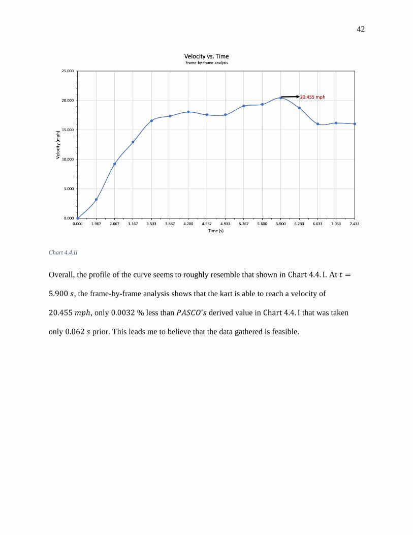
Chart 4.4.II
Overall, the profile of the curve seems to roughly resemble that shown in Chart 4.4. I. At 𝑡 =
5.900 𝑠, the frame-by-frame analysis shows that the kart is able to reach a velocity of
20.455 𝑚𝑝ℎ, only 0.0032 % less than 𝑃𝐴𝑆𝐶𝑂’𝑠 derived value in Chart 4.4. I that was taken
only 0.062 𝑠 prior. This leads me to believe that the data gathered is feasible.
43
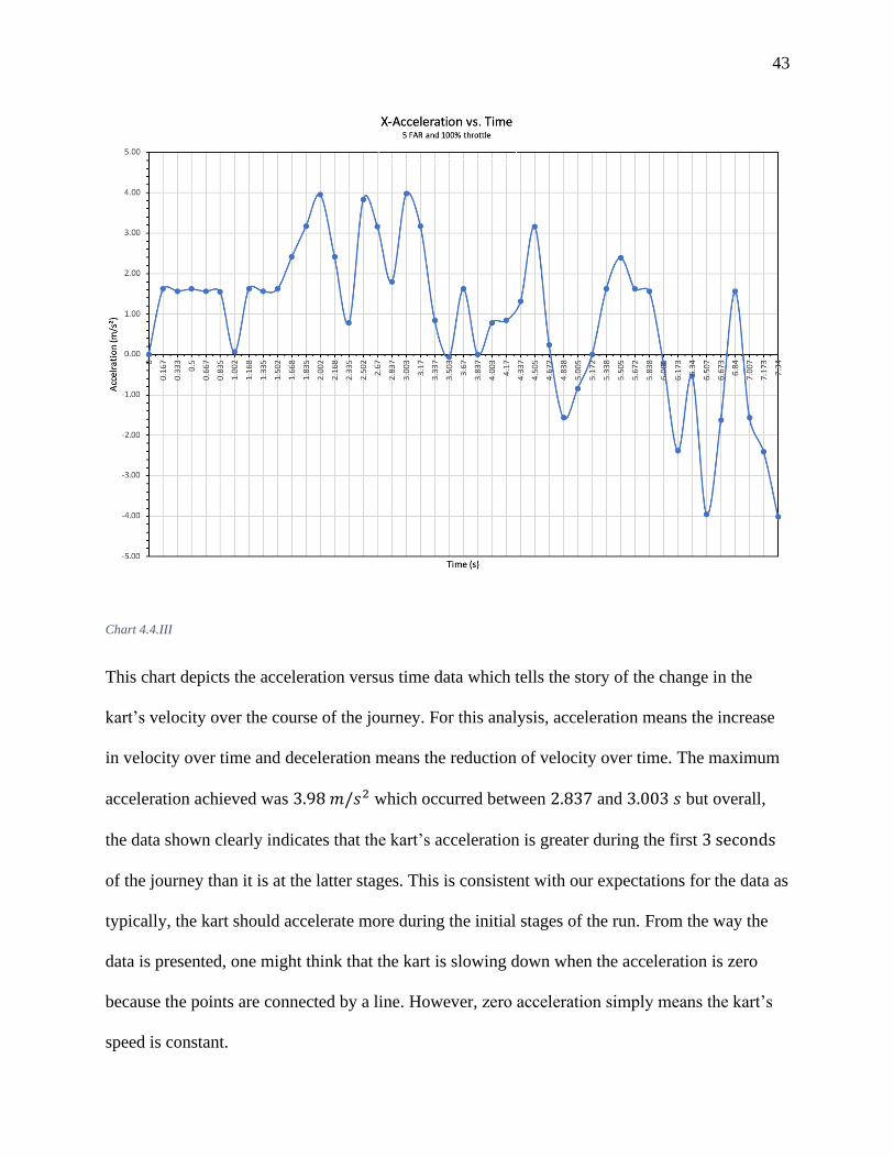
Chart 4.4.III
This chart depicts the acceleration versus time data which tells the story of the change in the
kart’s velocity over the course of the journey. For this analysis, acceleration means the increase
in velocity over time and deceleration means the reduction of velocity over time. The maximum
acceleration achieved was 3.98 𝑚/𝑠2 which occurred between 2.837 and 3.003 𝑠 but overall,
the data shown clearly indicates that the kart’s acceleration is greater during the first 3 seconds
of the journey than it is at the latter stages. This is consistent with our expectations for the data as
typically, the kart should accelerate more during the initial stages of the run. From the way the
data is presented, one might think that the kart is slowing down when the acceleration is zero
because the points are connected by a line. However, zero acceleration simply means the kart’s
speed is constant.

44
Chart 4.4.IV
This chart shows the kinetic energy versus time and predictably, confirms that greater velocities
yield greater kinetic energy.

45
Chart 4.4.V
The chart presented above is the power output of the engine that goes towards its kinetic energy
versus time and as stated earlier, this was derived using Equation 4.15. From the chart, we see
that the maximum power output was about 3.99 𝐻𝑃 at 4.505 𝑠. This might seem strange at first
because as stated earlier, the maximum acceleration was achieved at 3.003 s. And since power
here is calculated as the change in kinetic energy over time, the point with the greatest
acceleration should give us the greatest change in velocity and hence, the greatest change in
kinetic energy. This means one could reasonably expect the maximum power output to be at this
point. However, the key realization here is that the change in kinetic energy is the difference of
two squares, i.e.;

46
∆𝐾. 𝐸 =
1
2𝑚(�⃑� 𝑓
2− �⃑� 𝑖
2) [4.19]
As opposed to,
∆𝐾. 𝐸 =
1
2𝑚(�⃑� 𝑓 − �⃑� 𝑖)
2 [4.20]
Where �⃑� 𝑓 and �⃑� 𝑖 are the final and initial velocities respectively. This means that the difference
between the velocities isn’t the only thing accounted for but the magnitude of the velocities
matter as well. Let’s take these two points as an example. From the data presented in
Table 4.4. A, we see that the change in velocity from 4.337 𝑠 to 4.505 𝑠 is 0.53 𝑚/𝑠
Time (s) Velocity
(m/s)
Velocity (mph) Acceleration
(m/s²)
Kinetic
Energy (J)
Power
(HP)
4.337 7.8 17.45 1.32 3557.25 1.58862892
4.505 8.33 18.63 3.15 4057.09 3.98988955
While, the change in velocity between 2.837 and 3.003 𝑠 is 0.66 𝑚/𝑠.
Time (s) Velocity
(m/s)
Velocity (mph) Acceleration
(m/s²)
Kinetic
Energy (J)
Power
(HP)
2.837 5.72 12.79 1.80 1913.01 1.56909736
3.003 6.38 14.27 3.98 2379.94 3.7720821
So, when just the velocities are computed and taken as the squared difference Equation 4.20, we
find that;
(�⃑� 𝑓 − �⃑� 𝑖)2 = (6.38 − 5.72)2 = 0.4356 > (8.33 − 7.8)2
= 0.2809
However, compute it as the difference of the two squares and we see that,
(�⃑� 𝑓2− �⃑� 𝑖
2) = (6.382 − 5.722) = 7.986 < (8.332 − 7.82)
= 8.549
47
So, in terms of the change in kinetic energy, this means that it takes more work to increase the
velocity of a moving object at higher speeds than it does when it’s moving really slowly. This is
the reason why the maximum power output is at the 4.505 𝑠 mark.
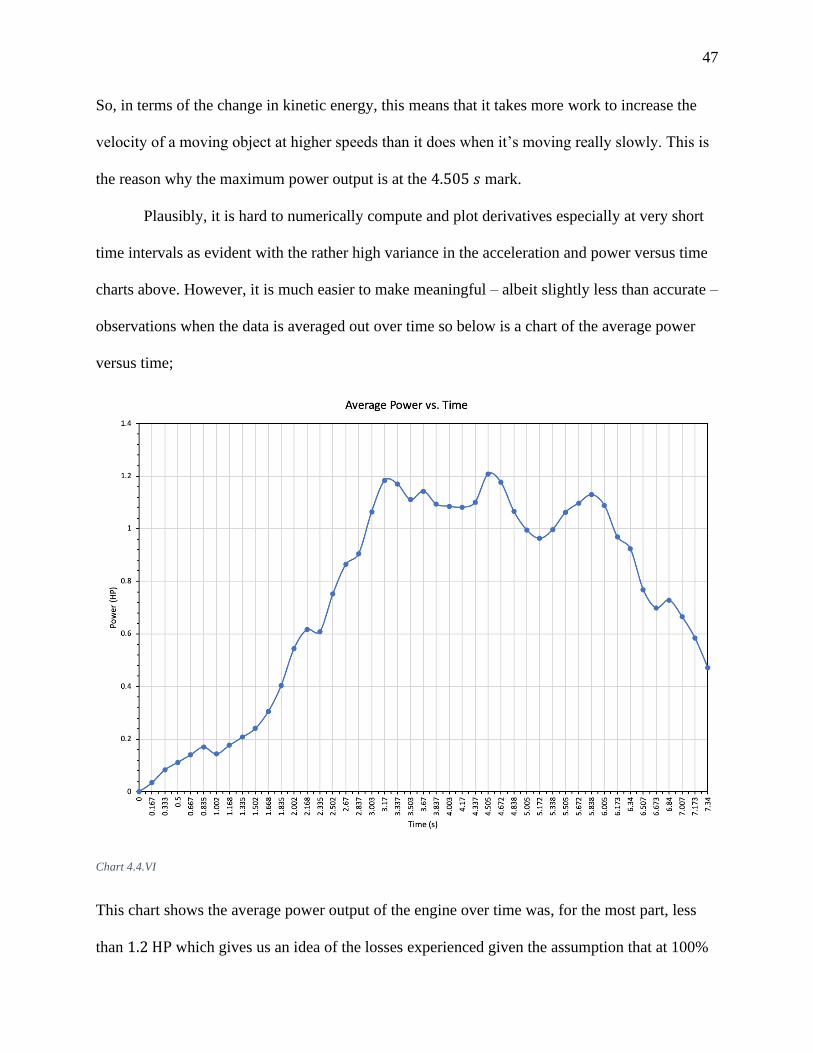
Plausibly, it is hard to numerically compute and plot derivatives especially at very short
time intervals as evident with the rather high variance in the acceleration and power versus time
charts above. However, it is much easier to make meaningful – albeit slightly less than accurate –
observations when the data is averaged out over time so below is a chart of the average power
versus time;
Chart 4.4.VI
This chart shows the average power output of the engine over time was, for the most part, less
than 1.2 HP which gives us an idea of the losses experienced given the assumption that at 100%
48
throttle and max 𝑅𝑃𝑀, the engine should output the full 6.5 𝐻𝑃. This means at the peak average
of 1.206 𝐻𝑃 – from the chart above – about 5.3𝐻𝑃 is being lost to the surroundings and means
the engine operates at a meager 18.46 % efficiency. Now, I understand that the losses
experienced at this instance and several others during the run are actually much smaller than
5.3 𝐻𝑃. But this chart is simply a means of getting a general sense of the inefficiency of the
engine and kart in transferring energy from chemical to kinetic without having to worry about
the negative power values found at several instances. The key takeaway here is that a significant
amount of energy is being lost to heat, sound, vibration and several other factors which certainly
contributed to the fact that the maximum velocity was not reached. Internal combustion engines
are typically not very efficient, and the evidence shown here supports that. On average, most IC
engines are around 20 % thermally efficient.

49
5 Summary
In this project, I have outlined a few features of vehicle operation as well as provided a step-by-
step guide on how to carry out the construction of a go-kart from wood. Both experiments
carried out were successful as the turn radius tests yielded results within the range of
experimental accuracy (5%) and the velocity of the go-kart crossed the 20 𝑚𝑝ℎ threshold as
desired. Furthermore, the investigation and applications of the velocity data collected by
𝑃𝐴𝑆𝐶𝑂 𝐶𝑎𝑝𝑠𝑡𝑜𝑛𝑒 yielded results that were used to give us a sense of the nature of velocity
versus time graphs, as well as the relationship between kinetic energy and the velocity of a
vehicle. Likewise, I was also able to point out the key relationship between the work necessary to
increase the velocity of a vehicle and its speed; more work is needed to do this at higher speeds
than at lower speeds. Finally, I plotted the average power output of the go-kart – that went into
its translational velocity – against time and found that a significant amount of the 6.5HP was
being lost to heat and other inefficiencies which isn’t atypical of internal combustion engines.
50
6 Possible Modifications
Through the process of building and testing out the kart, I noticed a few shortcomings and so in
this section I suggest possible modifications to improve the overall performance of the kart.
These are specifically for go-karts made out of wood.
6.1 Steering Modifications
The steering plank could be fitted with footrests and a sturdy spring-like chord – like a bungee
cord - that connects the plank to the vehicle’s frame and acts as a steering alignment aid. The
chord should be calibrated in such a way that after turning, it exerts a force on the plank and
resets it to 0 degrees. Furthermore, a bearing could be installed in the steering plank mount to
allow for increased agility. Another possible steering improvement would be to use a rear axle
that connects both wheels instead of using individual bolts. This ensures both rear wheels are in
line with one another and improves stability.
51
6.2 Minimizing Flexing of the Wooden Frame
During frame assembly, the plywood base is susceptible to flexing if the planks used for support
don’t have the same thickness or aren’t completely flat and straight. Flexing/Bending can lead to
issues like the misalignment of the drive wheel and sprocket. This can become very problematic
over time as the chain, due to the misalignment, would pop out of the sprocket ever so often
while driving and it makes for harder maintenance. So, ensuring the supports are flat and have
the same thickness should improve the overall stability of the kart, as well as the longevity of the
sprocket-clutch alignment.

52
Appendix A – Wood Cutouts
G
2.0
83 ft =
25
in
0.7
08 ft =
8 ½
in
B
4 ft =
48 in
I
A
1ft =
12
in
E
1.8
75 ft =
22
½ in
1
C
F H
1.5
4 ft =
18
½ in
D
2 ft 4 in = 28 in
inches
4 ft =
48 in
J
2 ft 6 in = 30 in
inches
NOTE:
• B, C, D, E, F, G, I and J were all cut from 2” x 4” planks
• A and H were cut from the 1 ½” thick plywood sheet.
K

53
LABEL PURPOSE NO. USED
A Plywood base 1
B L & R Vertical Support beams/
planks 2
C Central Support beam/ plank &
Steering beam mount 1
D
Front, Center and Rear
horizontal support beams/
planks
3
E Steering beam/plank 1
F Seat Back supports 3
G Side guards for seat 2
H Seatback 1
I Handlebar mount 1
J Handlebar mount support 1
K Wooden brake mount block 1
Table A 1 – Labelled Cuts

54
Appendix B – Other Important Data & Calculations Table B 1 – Total weight calculation.
Label Element No.
Used
Unit Size
(Inches)
Unit
Weight
(Kg)
Total Size
(Inches)
Total
Weight
(kg)
A Plywood Board 1 2 x 2 0.017 28 x 48 5.712
B L &R Vertical
Support Plank 2 12 0.297 48 2.376
C Central Beam
(Steering Mount) 1 12 0.297 70.5 1.744875
D Horizontal Support
Plank 3 12 0.297 28 2.079
E Steering Plank 1 12 0.297 30 0.7425
F Seat Back Support 3 12 0.297 12 0.891
G Seat railings/Side
guard 2 12 0.297 18.5 0.91575
H Seatback 1 2 x 2 0.017 12 x 28 1.428
I Handlebar Mount 1 12 0.297 25 0.61875
J Handlebar Mount
support 1 12 0.297 8.5 0.210375
*Note*:
For B, C, D, E, F, G, I & J
Size and Total Size indicated is the length of the plank since they are all 2x4’s
L Tire 4 3.26587 13.06348
M Sprocket 1 1.926 1.926
N Bruno (Driver) 1 61.235 61.235
O Engine 1 17.055 17.055
P Brake drum 1 0.324 0.324
Q
Square tubing
(Galvanized Steel
rails)
8 0.179 1.432
R PVC pipe 2 0.068 0.136
S Chain 1 0.848 0.848
T Wheel bolt 4 0.405 1.62
U Handlebars 1 1.55 1.55
V Wood to square
tubing bolts 16 0.055 0.88
W Brake band 1 0.15 0.15
TOTAL
WEIGHT: 116.93773

55
Table B 2 – Maximum velocity calculation
Other Required Data: Unit Calculate Top Speed Unit
Engine HP 6.5 HP Wheel C (dynamic) 42.40993
003
Inch
es
Engine RPM 3600 RP
M Wheel C (dynamic)
3.534160
836 Feet
Sprocket tooth # 60 n/a Gear Ratio = Sprocket
tooth/Clutch 6 n/a
Clutch tooth # 10 n/a wRPMS = Engine RPM/
Gear ratio 600
RP
M
Drive-wheel diameter
(free) 14.5
Inch
es
Max V in ft/min = C
*wRPMS
2120.496
501
ft/mi
n
Drive-wheel diameter
(dynamic)
13.49
95
Inch
es V in ft/hr.
127229.7
901 ft/hr.
V in mph 24.09655
115 Mph

56
Appendix C – Parts List *Bolt Specification Sample - XYZ Bolt: ½” (Diameter). Bolts:1 − 5” (L) (should be read as: one, five-inch-long
bolt)
1. 6.5 HP 212 cc Predator Engine
All parts from 3 to 12 can be found here: https://www.mcmaster.com
2. 4” x 8” Plywood (This can vary depending on preference)
3. Wheel Bolts: 5/8” (D). Bolts: 2 − 8” (L), 2 − 12” (L) and 8 washers
4. Deck screws: 3 ½” 5. Engine/Brake Bolt: 5/16” (D). Bolts: 1-5” (L), 2-2” (L), 1 − 4” (L), 1 − 3 ½” (L) and 10
Washers
6. Steering Bolt: ½” (D) Bolt: 1 − 6” (L) and 6 washers
7. Wood to metal Bolts: 3/8” (D) Bolts: 18 − 4” (L) and 36 washers
8. Lock nuts for all Bolts
9. 2 U bolts for handlebars ¼” × 11/8” × 2” 10. Braces for seats: 4” Heavy duty Corner Braces
11. Wheel spacers: ¾” round tube
12. Galvanized Steel Rail for Bolt-Together Framing. 11
2" High x 1
1
2" Wide, 0.105" Wall
Thickness
All parts from 13 to 26 can be found here: https://www.gopowersports.com
13. 4” Manco Brake band with clip
14. Throttle twist grip 7/8” (D) [75” 90 − degree bend]
15. Brake band pin
16. 60” Brake cable with 3/8” Barrel on one end
17. Left- and Right-hand shorty lever assembly
18. Push button
19. 420 Chain
20. 10T, 3/4" bore, Centrifugal Clutch, #41/420
21. Minibike Handlebars, Mega Moto 80/105, Complete Kit-Unassembled
22. 145x70-6 Drive Wheel Assembly Complete with 5/8” Bearings, Sprocket and Brake
Drum (60 Tooth Sprocket #41/420) (1)
23. 145x70-6 Floater Wheel Assembly Complete with 5/8” sealed bearings (Knobby) (3)
24. Drive Wheel [5” (D) with 5/8” bearing]16
25. 4” Brake Drum, 1246 Manco17
26. Sprocket [48 Tooth]18
16 Only necessary if drive wheel is purchased unassembled 17 Only necessary if drive wheel is purchased unassembled 18 Only necessary if drive wheel is purchased unassembled
57
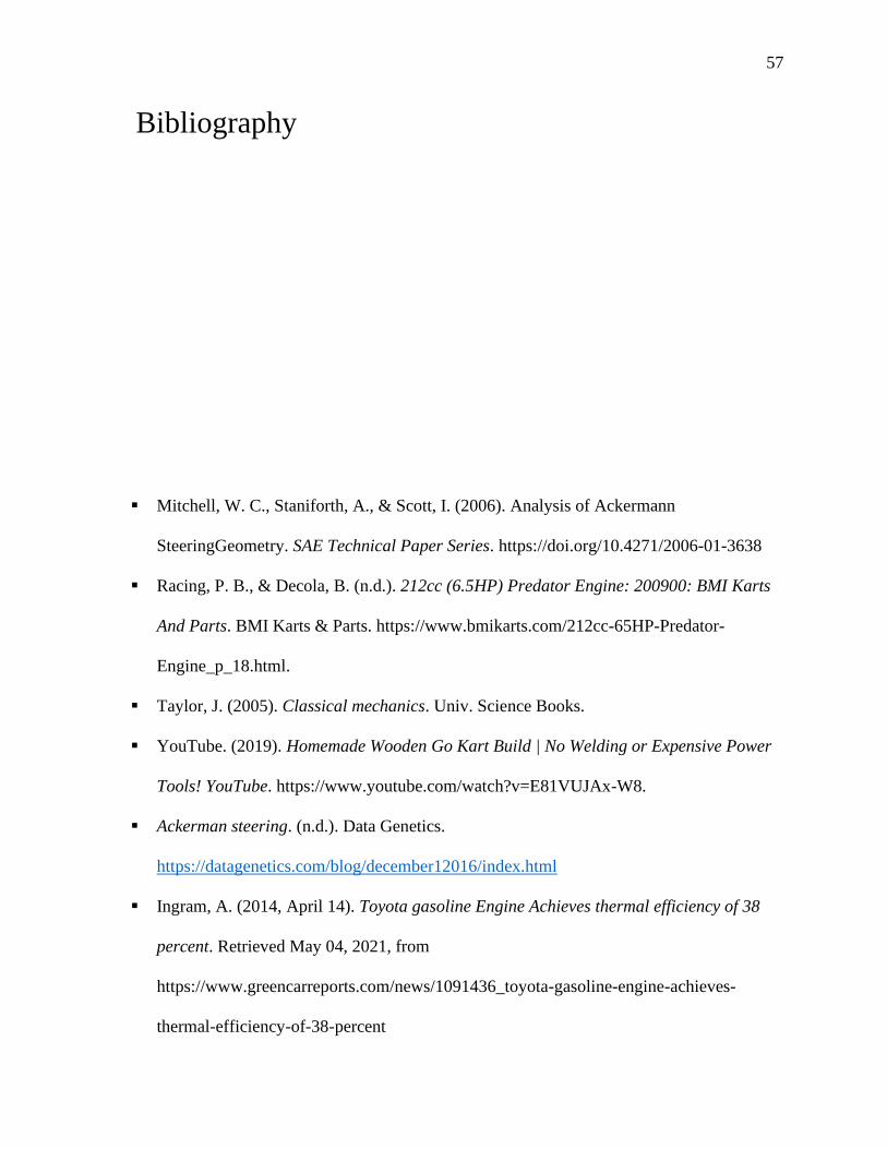
Bibliography
▪ Mitchell, W. C., Staniforth, A., & Scott, I. (2006). Analysis of Ackermann
SteeringGeometry. SAE Technical Paper Series. https://doi.org/10.4271/2006-01-3638
▪ Racing, P. B., & Decola, B. (n.d.). 212cc (6.5HP) Predator Engine: 200900: BMI Karts
And Parts. BMI Karts & Parts. https://www.bmikarts.com/212cc-65HP-Predator-
Engine_p_18.html.
▪ Taylor, J. (2005). Classical mechanics. Univ. Science Books.
▪ YouTube. (2019). Homemade Wooden Go Kart Build | No Welding or Expensive Power
Tools! YouTube. https://www.youtube.com/watch?v=E81VUJAx-W8.
▪ Ackerman steering. (n.d.). Data Genetics.
https://datagenetics.com/blog/december12016/index.html
▪ Ingram, A. (2014, April 14). Toyota gasoline Engine Achieves thermal efficiency of 38
percent. Retrieved May 04, 2021, from
https://www.greencarreports.com/news/1091436_toyota-gasoline-engine-achieves-
thermal-efficiency-of-38-percent