investigating the effect of interrupted cathodic … university institutional repository...
TRANSCRIPT
Loughborough UniversityInstitutional Repository
Investigating the effect ofInterrupted Cathodic
Protection on reinforcedconcrete structures
This item was submitted to Loughborough University's Institutional Repositoryby the/an author.
Citation: CHRISTODOULOU, C. ... et al, 2010. Investigating the effect ofInterrupted Cathodic Protection on reinforced concrete structures. Presentedat EUROCORR 2010, 13 - 17 September 2010, Moscow, Russia.
Additional Information:
• This is a conference paper.
Metadata Record: https://dspace.lboro.ac.uk/2134/8983
Version: Accepted for publication
Publisher: The European Corrosion Congress
Please cite the published version.

This item was submitted to Loughborough’s Institutional Repository (https://dspace.lboro.ac.uk/) by the author and is made available under the
following Creative Commons Licence conditions.
For the full text of this licence, please go to: http://creativecommons.org/licenses/by-nc-nd/2.5/
1
Investigating the effect of Interrupted Cathodic Protection on
reinforced concrete structures
Christian Christodoulou a, Gareth Glass a, John Webb a, Simon Austin b,
Chris Goodier b
a: AECOM Europe, 94-96 Newhall Street, Birmingham, B3 1PB, U.K.
b: Loughborough University, Department of Civil and Building Engineering,
Loughborough, U.K.
e-mail to: [email protected]
Abstract
Impressed Current Cathodic Protection (ICCP) has been one of the major
components of the repair and maintenance strategy on many motorway structures in
the U.K. It has helped to prolong the life of more than 700 structures, in a significantly sustainable manner, by reducing the need to remove chloride contaminated (but
otherwise sound) concrete. This study was initiated after identifying that some of the
ICCP systems were reaching the end of their design life and required a significant
level of maintenance (including anode replacement) to operate in accordance with
the latest Codes of Practice. In addition, there were a number of structures where the application of ICCP has been interrupted due to severe anode deterioration or
vandalism.
The objective of this work was to collate evidence from structures to support
preliminary laboratory results that the application of ICCP to a reinforced concrete structure over a period of time can transform the environment around the
reinforcement, even after the protective current has been interrupted.
This experimental field study interrupted the current to ten structures which had been
protected with ICCP between 5 and 16 years and corrosion rates were monitored to determine when reinforcement corrosion will initiate again.
It was found that after five or more years of ICCP, the steel remained passive for at
least 30 months after interrupting the protective current, despite the presence of
chloride contamination representing a substantial corrosion risk. In some cases, severe anode deterioration meant that the current was interrupted at an unknown
point in time prior to the initiation of the scheme.
Four main conclusions are drawn regarding this approach: it can give an indication of
when repairs to ICCP systems are likely to be critical; provide new evidence for the design lives attributed to systems using lower cost anodes; reduce the requirement to
replace systems at the end of their functional lives; and potentially extend the interval
2
between planned maintenance of existing systems with corresponding reduction in
monitoring frequency, cost and disruption.
1. Introduction
Impressed Current Cathodic Protection (ICCP) is an electrochemical treatment for
the arrest and prevention of corrosion. It has been widely and successfully used on reinforced concrete structures since the first application in the 1970s on a bridge
deck in the USA [1]. The main protection mechanism of ICCP has been associated
with a negative steel polarisation [2].
However, it is widely accepted that the application of ICCP to reinforced concrete structure transforms the environment around the reinforcement over a period of time
[3, 4, 5]. The metal surface is polarised negatively, thus repelling the chlorides (Cl-);
oxygen (O2) and water (H2O) are consumed and hydroxyls (OH-) are generated at
the metal surface. The hydroxyls’ alkalinity will then be responsible for restoring the
pH to the metal surface and inducing passivity of the metal. These are the secondary beneficial effects following the application of ICCP.
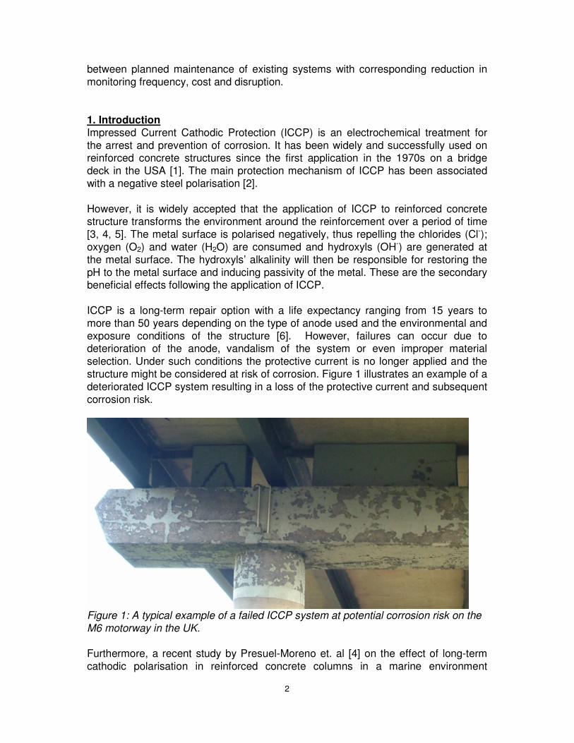
ICCP is a long-term repair option with a life expectancy ranging from 15 years to
more than 50 years depending on the type of anode used and the environmental and
exposure conditions of the structure [6]. However, failures can occur due to deterioration of the anode, vandalism of the system or even improper material
selection. Under such conditions the protective current is no longer applied and the
structure might be considered at risk of corrosion. Figure 1 illustrates an example of a
deteriorated ICCP system resulting in a loss of the protective current and subsequent
corrosion risk.
Figure 1: A typical example of a failed ICCP system at potential corrosion risk on the
M6 motorway in the UK.
Furthermore, a recent study by Presuel-Moreno et. al [4] on the effect of long-term
cathodic polarisation in reinforced concrete columns in a marine environment
3
illustrated that corrosion will not initiate immidiately after the protective current was
interrupted. The structures tested were partially submerged, with the splash zone exposed to very high chloride contamination levels, in cases up to 4.7% by weight of
cement and therefore they had a significant risk of corrosion. The study concluded
that given enough time the corrosion could initiate on all the reinforcement again.
However, the results show that ICCP has persistent protective benefits and for that
reason corrosion did not initiate right away after interruption of the protective current in an aggressive marine environment.
The present work aimed to identify the existence of these persistent secondary
protective effects afforded by the application of ICCP in a number of field structures.
The Midland Links Motorway Viaducts (incorporating parts of the M5, M6 and M42 motorways and associated trunk roads) represent the largest application of ICCP in
the U.K., with over 700 reinforced concrete structures being protected by ICCP. Data
has been collected from some of these in-service structures and has been compared
with published laboratory data.
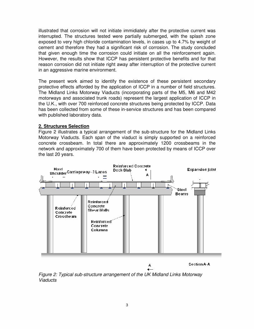
2. Structures Selection
Figure 2 illustrates a typical arrangement of the sub-structure for the Midland Links
Motorway Viaducts. Each span of the viaduct is simply supported on a reinforced
concrete crossbeam. In total there are approximately 1200 crossbeams in the
network and approximately 700 of them have been protected by means of ICCP over the last 20 years.
Figure 2: Typical sub-structure arrangement of the UK Midland Links Motorway Viaducts
4
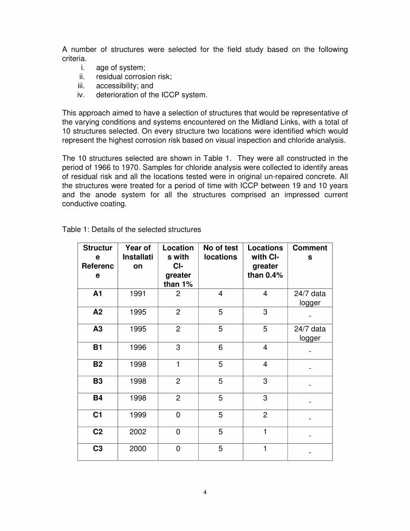
A number of structures were selected for the field study based on the following
criteria. i. age of system;
ii. residual corrosion risk;
iii. accessibility; and
iv. deterioration of the ICCP system.
This approach aimed to have a selection of structures that would be representative of
the varying conditions and systems encountered on the Midland Links, with a total of
10 structures selected. On every structure two locations were identified which would
represent the highest corrosion risk based on visual inspection and chloride analysis.
The 10 structures selected are shown in Table 1. They were all constructed in the
period of 1966 to 1970. Samples for chloride analysis were collected to identify areas
of residual risk and all the locations tested were in original un-repaired concrete. All
the structures were treated for a period of time with ICCP between 19 and 10 years
and the anode system for all the structures comprised an impressed current conductive coating.
Table 1: Details of the selected structures
Structur
e
Referenc
e
Year of
Installati
on
Location
s with
Cl-
greater
than 1%
No of test
locations
Locations
with Cl-
greater
than 0.4%
Comment
s
A1 1991 2 4 4 24/7 data
logger
A2 1995 2 5 3 -
A3 1995 2 5 5 24/7 data
logger
B1 1996 3 6 4 -
B2 1998 1 5 4 -
B3 1998 2 5 3 -
B4 1998 2 5 3 -
C1 1999 0 5 2 -
C2 2002 0 5 1 -
C3 2000 0 5 1 -

5
3. Assessment Methodology
The following testing regimes were employed in order to assess residual corrosion activity:
a) corrosion potential measurements, undertaken monthly and in some cases
continuously;
b) polarisation resistance determination of corrosion rates, undertaken monthly to calculate corrosion rates; and
c) impedance measurement of corrosion rates initiated after 6 months.
Correlating the off steel potentials with a corrosion risk probability is a well
established technique [7, 8, 9]. In general, more positive measurements with a flat trend over time indicate that there is small corrosion risk whereas values with a
negative rend over time indicate a residual corrosion risk [10].
Corrosion rates are usually expressed as a current density, a rate of weight loss or a
rate of section loss. A corrosion rate of 1 mA/m2 when expressed as a current density is approximately equal to a steel weight loss of 10g/m2/year or a steel section loss of
1µm/year. Higher corrosion rates are considered to be significant and in cases where
there is easy access of oxygen (i.e. non-saturated with water) then average corrosion
rates can reach values up to 100 mA/m2 [11]. The calculation of corrosion rates
through the polarisation resistance method is an established technique and its feasibility has been demonstrated in numerous occasions [12, 13, 14].
Impedance is an alternative technique to calculate corrosion rates and was added to
the testing regime during this project to provide additional data. Impedance testing
differs from polarisation resistance testing in the form of the perturbation applied and the subsequent data analysis. A current pulse delivers a charge to the steel that
affects the steel potential and the potential response is recorded and analysed [15].
4. Testing Arrangement
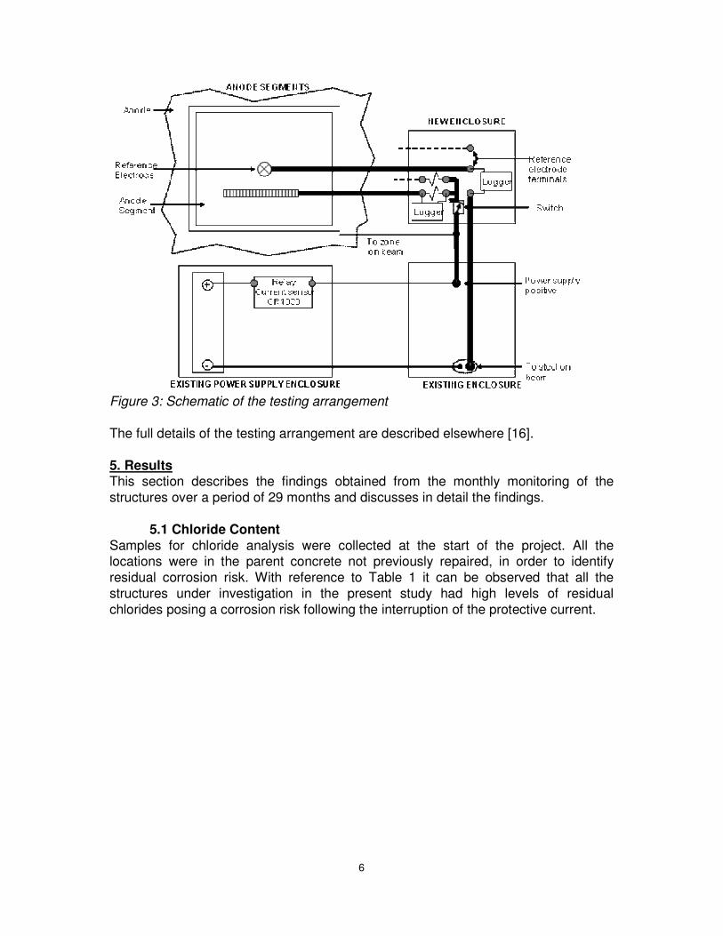
The arrangement used to assess steel passivity is illustrated in Figure 3. The main elements were the existing power supply enclosure located at ground-level, the
existing ICCP enclosure at high-level, the anode segment and a new enclosure at
high-level to facilitate the new connections to the system.
6
Figure 3: Schematic of the testing arrangement
The full details of the testing arrangement are described elsewhere [16].
5. Results This section describes the findings obtained from the monthly monitoring of the
structures over a period of 29 months and discusses in detail the findings.
5.1 Chloride Content
Samples for chloride analysis were collected at the start of the project. All the locations were in the parent concrete not previously repaired, in order to identify
residual corrosion risk. With reference to Table 1 it can be observed that all the
structures under investigation in the present study had high levels of residual
chlorides posing a corrosion risk following the interruption of the protective current.
7
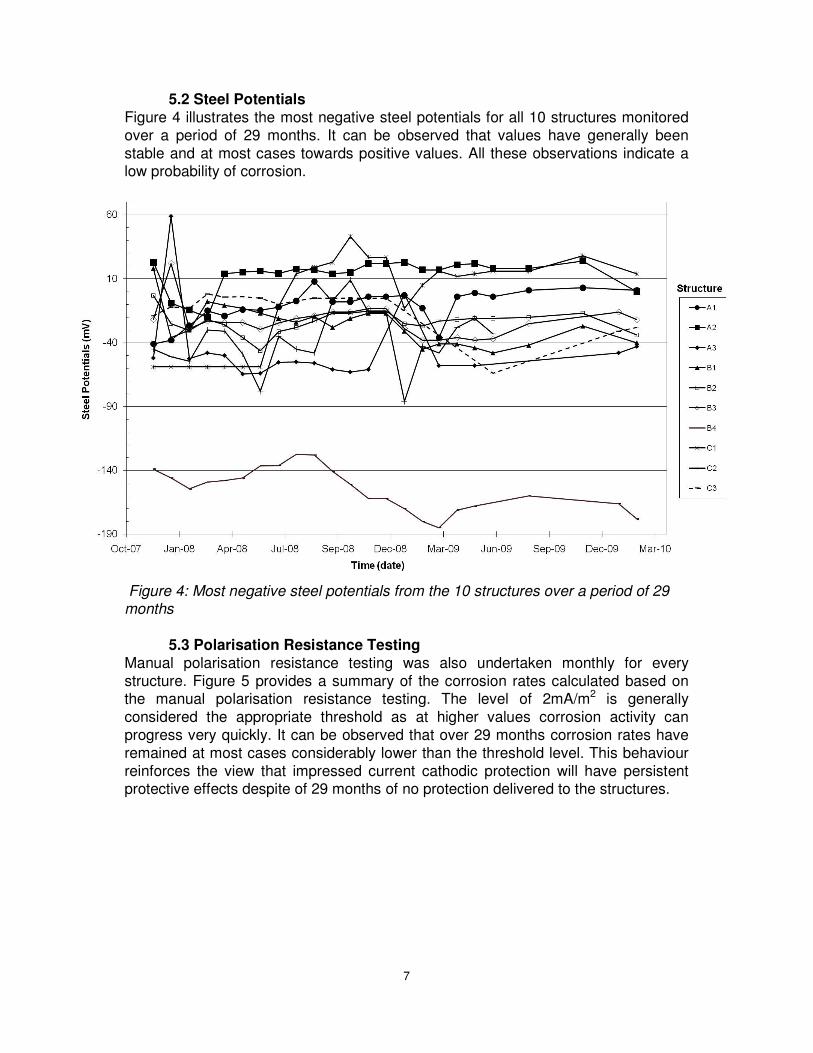
5.2 Steel Potentials
Figure 4 illustrates the most negative steel potentials for all 10 structures monitored
over a period of 29 months. It can be observed that values have generally been
stable and at most cases towards positive values. All these observations indicate a low probability of corrosion.
Figure 4: Most negative steel potentials from the 10 structures over a period of 29 months
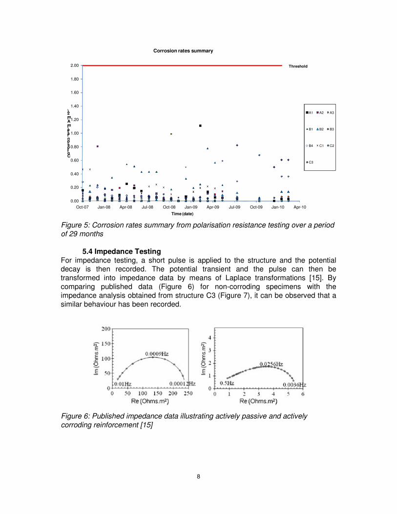
5.3 Polarisation Resistance Testing
Manual polarisation resistance testing was also undertaken monthly for every
structure. Figure 5 provides a summary of the corrosion rates calculated based on the manual polarisation resistance testing. The level of 2mA/m2 is generally
considered the appropriate threshold as at higher values corrosion activity can
progress very quickly. It can be observed that over 29 months corrosion rates have
remained at most cases considerably lower than the threshold level. This behaviour
reinforces the view that impressed current cathodic protection will have persistent protective effects despite of 29 months of no protection delivered to the structures.
8
0.00
0.20
0.40
0.60
0.80
1.00
1.20
1.40
1.60
1.80
2.00
Oct-07 Jan-08 Apr-08 Jul-08 Oct-08 Jan-09 Apr-09 Jul-09 Oct-09 Jan-10 Apr-10
Corrosion rate (mA/m2)
Time (date)
Corrosion rates summary
A1 A2 A3
B1 B2 B3
B4 C1 C2
C3
Threshold
Figure 5: Corrosion rates summary from polarisation resistance testing over a period
of 29 months
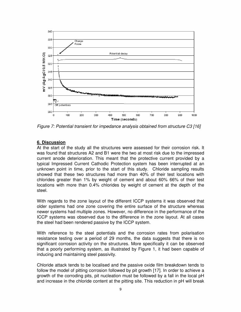
5.4 Impedance Testing
For impedance testing, a short pulse is applied to the structure and the potential decay is then recorded. The potential transient and the pulse can then be
transformed into impedance data by means of Laplace transformations [15]. By
comparing published data (Figure 6) for non-corroding specimens with the
impedance analysis obtained from structure C3 (Figure 7), it can be observed that a
similar behaviour has been recorded.
Figure 6: Published impedance data illustrating actively passive and actively
corroding reinforcement [15]
9
Figure 7: Potential transient for impedance analysis obtained from structure C3 [16]
6. Discussion
At the start of the study all the structures were assessed for their corrosion risk. It was found that structures A2 and B1 were the two at most risk due to the impressed
current anode deterioration. This meant that the protective current provided by a
typical Impressed Current Cathodic Protection system has been interrupted at an
unknown point in time, prior to the start of this study. Chloride sampling results
showed that these two structures had more than 40% of their test locations with chlorides greater than 1% by weight of cement and about 60% 66% of their test
locations with more than 0.4% chlorides by weight of cement at the depth of the
steel.
With regards to the zone layout of the different ICCP systems it was observed that older systems had one zone covering the entire surface of the structure whereas
newer systems had multiple zones. However, no difference in the performance of the
ICCP systems was observed due to the difference in the zone layout. At all cases
the steel had been rendered passive by the ICCP system.
With reference to the steel potentials and the corrosion rates from polarisation
resistance testing over a period of 29 months, the data suggests that there is no
significant corrosion activity on the structures. More specifically it can be observed
that a poorly performing system, as illustrated by Figure 1, it had been capable of
inducing and maintaining steel passivity.
Chloride attack tends to be localised and the passive oxide film breakdown tends to
follow the model of pitting corrosion followed by pit growth [17]. In order to achieve a
growth of the corroding pits, pit nucleation must be followed by a fall in the local pH
and increase in the chloride content at the pitting site. This reduction in pH will break

10
up the passive oxide film protecting the reinforcement. This together with the
presence of chloride ions will promote the dissolution of iron and production of
hydrochloric acid [17]. This is also commonly called acidification of the metal–
concrete interface.
Based on this model, corrosion is dependent on the acidification. This also explains
why corrosion activity will initiate at different rates in different environments. As a
result, a reservoir of inhibitive hydroxide ions, which may be present in some solids,
affects the corrosion process. Solid phase inhibitors release hydroxide ions to inhibit corrosion damage [18]. Other factors such as pore solution, moisture, and
temperature and oxygen depletion will affect the mechanism; however the reservoir
of hydroxide ions is the dominant factor.
The results of the field study presented here confirmed the suggestion that long term-application of ICCP has a persistent protective effect. The protective current
has been interrupted for 29 months and the off steel potentials have shifted towards
more positive values and have remained passive, despite the fact that some of the
beams experienced unplanned interruptions of the ICCP system. Furthermore, all
the structures investigated had a substantial corrosion risk as there were several locations with chloride levels higher than 1% by weight of cement.
7. Asset Management
The results of this field study can help improve the asset management strategy of
Maintenance Agencies. When considering the repair of old ICCP systems the passivation of the reinforcement from the previous system should be taken under
consideration. Therefore, the new ICCP system needs only to be designed for
corrosion prevention rather than corrosion protection. With this approach, the
existing power supply could be utilised if it is still functioning as the power
requirements for cathodic prevention are far lower than for cathodic protection [2]. In addition, other forms of corrosion management should be considered, such as
monitoring only, concrete repairs, galvanic anodes etc. Alternatively, the failed ICCP
systems can just be periodically monitored until corrosion activity becomes
significant and the ICCP system can then be renewed. Overall, this approach should
result in reduced refurbishment and maintenance costs of ICCP systems.
In addition, the results of the study illustrate that improvements can be achieved on
the design aspect of ICCP systems. The systems inspected here comprised a
conductive coating anode with all of them being able to deliver a current density up
to 20 mA/m2 on the concrete surface. These anodes are deemed to offer low current densities when compared with the more powerful MMO/Ti mesh anode systems that
are typically used nowadays.
With the steel density on the structures inspected varying between 1.4 to 2.2 times
the concrete surface area it can be understood that the systems were delivering a low density protective current. However, the results of this study have illustrated that
this low protective current has been sufficient to induce and sustain steel passivity.
This is despite the fact that protection was interrupted 29 months ago and several
structures had a significant corrosion risk with chloride contamination in excess of
11
1% by weight of cement. Furthermore, Polder et al. [19] also illustrated that only a
small current will be sufficient to induce and sustain passivity
In addition, the results of this study also have an impact on the monitoring needs of a typical ICCP system. It has been shown that corrosion risk will in general be low
even if the protective current has been interrupted for 29 months. Therefore, a basis
now exists to reduce monitoring intervals to annual. This approach can result in cost
benefits for the Maintenance Agencies.
Finally, the number of power supplies is a contributing factor to rising costs. Limiting
the number used can therefore also contribute towards a more cost-effective ICCP
design. The results obtained from this research illustrate that no apparent deference
has been observed in the polarisation between single and multi-zone systems. As
such the number of zones used for the ICCP system can be reduced and as such limiting the need for numerous power supplies.
8. Conclusions
The site data presented here is consistent with the laboratory and other results
reported earlier, indicating a persistent protective effect after the interruption of ICCP systems. More specifically we conclude the following:
1) The cathodically protected steel was found to be in a passive state in all ten of
the protected structures investigated. Chloride levels never exceeded 2% at
the depth of the steel, although it needs to be noted that the structures were previously patch-repaired prior to the application of the ICCP. No apparent
difference in the corrosion risk of ICCP systems with different number of ICCP
zones was observed.
2) The polarisation resistance, steel potential and impedance data show that ICCP protects reinforced concrete structures not only by shifting potentials to
negative values (i.e. pitting potential model) but also by transforming the steel-
concrete interface.
3) After 20 months with no ICCP current, all the structures investigated have remained passive including cases where 60% of the test locations exceeded
1% chloride concentration at the depth of steel. This supports previous
laboratory evidence suggesting that ICCP does not only arrest ongoing
corrosion but it also prevents future corrosion by increasing the chloride
threshold of the structure.
4) The absence of corrosion should be taken into account when repairing old CP
systems. Replacement anode systems need only to be designed for
corrosion prevention rather than corrosion protection. Other forms of risk
management include just having corrosion rate monitoring on its own as opposed to repair of the ICCP system.
5) A less conservative design approach could be utilised. The low grade
conductive coating anode systems tested in this study have been capable of

12
inducing steel passivity in chloride contaminated concrete and these anodes
were never capable of sustaining more than 20 mA/m2 of concrete surface,
with steel surface area ranging between 1.4 to 2.2 times the concrete surface
area.
6) Monitoring intervals can be safely reduced to annual inspections, resulting
into further cost savings for the Maintenance Agencies. Power supplies can
also be reduced by decreasing the number of different zones. No difference
has been observed in the performance between single and multi-zone ICCP systems.
Acknowledgements
The authors acknowledge the support and invaluable help throughout all the stages
of this work of Chris Spence (Amey), Peter Gilbert (Amey), Dr. Vitalis Ngala (Mouchel) and Sam Beamish (Mouchel). They would also like to thank the Highways
Agency, AECOM and EPSRC for supporting the lead author throughout the duration
of this project.
References [1] Stratful R.F. 1973, Preliminary Investigations of Cathodic Protection of a Bridge
Deck, Caltrans,
http://www.dot.ca.gov/hq/research/researchreports/1973/bridge_deck.pdf (accessed
24th May 2010).
[2] BS EN 12696:2000, Cathodic Protection of Steel in Concrete, British Standards
Institution.
[3] Glass G. K. and Chadwick J. R. 1994, An investigation into the mechanisms of
protection afforded by a cathodic current and the implications for advances in the field of cathodic protection, Corrosion Science, 36, 12, pp. 2193 – 2209.
[4] Presuel – Moreno F.J., Sagüés A. A., Kranc S. C. 2002, Steel activation in
concrete following interruption of long-term cathodic polarisation, Corrosion 2002,
Paper no. 02259. [5] Glass G.K., Green W.K. and Chadwick J.R. 1991, Long-Term Performance of
Cathodic Protection Systems on Reinforced Concrete Structures, Proc. U.K.
Corrosion ’91, vol. 3 (Leighton Buzzard, Bedfordshire: Institute of Corrosion, 1991)
[6] Wyatt B. S. 2009, Developments in Cathodic Protection of Steel in Concrete: Concrete Bridge Development Group, Annual Conference: Eurocodes and
Innovation.
[7] Stratful R. E. 1957, The corrosion of steel in a reinforced concrete bridge,
Corrosion, 13, pp. 43 – 48.
[8] Vassie P.R. and McKenzie M. 1985, Electrode potentials for on-site monitoring of
atmospheric corrosion of steel, Corrosion Science, 25, pp. 1 – 13.
13
[9] Novokshchenov V. 1997, Corrosion surveys of prestressed bridge members
using a half-cell potential technique, Corrosion, 53 (6), pp. 489 – 498.
[10] BA 35/90, Inspection and repair of concrete highway structures, British Standards Institution.
[11] Broomfiled J. P. 1997, Corrosion of steel in concrete, understanding,
investigation and repair, London, U.K.: E & F. N. Spon.
[12] Stern M. and Geary AL.L. 1957, Electrochemical polarisation I: A theoretical
analysis of the shape of polarisation curves , Journal of Electrochemical Society,
104(1), pp. 56 – 63.
[13] Polder R., Tondi A., Cigna R. 1993, Concrete resistivity and corrosion rate of reinforcement, TNO report 93-BT-r0170, TNO Delft.
[14] Andrade C. and Alonso C. 2004, Test methods for on-site corrosion rate
measurement of steel reinforcement in concrete by means of the polarisation
resistance method, RILEM TC 154-EMC: Electrochemical techniques for measuring metallic corrosion, Materials and Structures, (37), pp. 623 – 643.
[15] Glass G. K., Hassaein A.M. and Buenfeld N. R. 1997, Obtaining Impedance
Information on the Steel – Concrete Interface, Corrosion, (54), pp. 887 – 897.
[16] Christodoulou C., Glass G., Webb J., Austin S. and Goodier C. 2010, Assessing
the long term benefits of Impressed Current Cathodic Protection, Corrosion Science,
(52), pp. 2671 – 2679, DOI information: 10.1016/j.corsci.2010.04.018.
[17] Glass G. K. & Buenfeld N. R. 1997, The presentation of the chloride threshold level for corrosion of steel in concrete, Corrosion Science, (39), pp. 1001 – 1013.
[18] Glass G. K., Roberts A.C. and Davison N. 2008, Hybrid corrosion protection of
chloride-contaminated concrete, Proceedings of the Institution of Civil Engineers,
Construction Materials, 161 (4), pp. 163 – 172.
[19] Polder R., Peelen W.H.A., Stoop B.T.J. and Neeft E.A.C. 2009, Early stage
beneficial effects of Cathodic Protection in Concrete Structures, Eurocorr 2009, Nice,
France.