investigating the classical and non-classical mechanical
TRANSCRIPT

University of New MexicoUNM Digital Repository
Electrical and Computer Engineering ETDs Engineering ETDs
Summer 5-6-2017
Investigating the classical and non-classicalmechanical properties of GaN nanowiresMohammad Reza Zamani KouhpanjiUniversity of New Mexico
Follow this and additional works at: https://digitalrepository.unm.edu/ece_etds
Part of the Electrical and Electronics Commons, Nanotechnology Fabrication Commons, OtherMechanical Engineering Commons, Semiconductor and Optical Materials Commons, and theStructural Materials Commons
This Thesis is brought to you for free and open access by the Engineering ETDs at UNM Digital Repository. It has been accepted for inclusion inElectrical and Computer Engineering ETDs by an authorized administrator of UNM Digital Repository. For more information, please [email protected].
Recommended CitationZamani Kouhpanji, Mohammad Reza. "Investigating the classical and non-classical mechanical properties of GaN nanowires." (2017).https://digitalrepository.unm.edu/ece_etds/354

i
Student Name: Mohammad Reza Zamani Kouhpanji
Candidate
Graduate Unit (Department): Electrical and Computer Engineering
Department
This thesis is approved, and it is accepted in quality and form for publication:
Approved by the Thesis Committee:
Dr. Tito Busani ,
Chairperson
Dr. Yu-Lin Shen
Dr. Francesca Cavallo
(Note: Type each committee member’s name on a single line; this will become the first page of front matter)

ii
Investigating the classical and non-classical mechanical properties of GaN nanowires
By
Mohammad Reza Zamani Kouhpanji
Bachelor of Science, Mechanical Engineering
Master of Science, Mechanical Engineering
Thesis
Submitted in Partial Fulfillment of the Requirements for the Degree of
Master of Science, Electrical Engineering
The University of New Mexico
Albuquerque, New Mexico
July 2017

iii
Investigating the classical and non-classical mechanical properties of GaN nanowires
By
Mohammad Reza Zamani Kouhpanji
M.S., Electrical Engineering, University of New Mexico, 2017
Abstract
Study and prediction of classical/non-classical mechanical properties of GaN is
crucial due to the potential application of GaN nanowires (NWs) in piezoelectric, probe-
based nanometrology, and nanolithography areas. GaN is mainly grown on sapphire
substrates whose lattice constant and thermal expansion coefficient are significantly
different from GaN. These discrepancies cause mechanical defects and high residual
stresses and strains in GaN, which reduce its quantum efficiency.
Specifically, for nanoscale applications, the mechanical properties of materials
differ significantly compared to the bulk properties due to size-effects. Therefore, it is
essential to investigate the mechanical properties of GaN NWs using the non-classical solid
mechanic theories, modified couple stress theory (MCST) and modified strain gradient
theory (MSGT).
Experimentally the GaN NWs were prepared by using top-down approach to etch
c-plane GaN layer grown in Metal Organic Chemical Vapor Deposition (MOCVD)
chamber to achieve high aspect ratio NWs with high uniformity. An Atomic Force
Microscope (AFM) was used to apply an infinitesimal deflection on the top of clamped-
free NWs while monitoring the lateral and normal forces.
According to the MCST, the Young’s modulus, shear modulus and length scale
were measured to be 323 GPa, 133 GPa and 13 nm, respectively, and according to the
MSGT, they were measured to be 319 GPa, 132 GPa and 8 nm, respectively. Furthermore,
a quantum mechanics based approached was conducted to estimate the classical/non-
classical mechanical properties of the GaN NWs as well.

iv
TABLE OF CONTENTS
Chapter 1: literature Review ............................................................................................... 1
1- Introduction ................................................................................................................. 1
2- GaN NWs .................................................................................................................... 1
3- Experimental techniques ............................................................................................. 6
3-1- Bending ................................................................................................................ 6
3-2- In Situ Resonance ................................................................................................ 7
3-3- Uniaxial loading ................................................................................................... 8
3-4- Nanoindentation ................................................................................................... 9
4- Solid mechanic theories ............................................................................................ 10
4-1- Cosserat theory................................................................................................... 11
4-2- Couple stress theory (MTK model) ................................................................... 12
4-3- Modified couple stress theory (YCLT model) ................................................... 14
4-4- Modified strain gradient theories ....................................................................... 15
Chapter 2: Modified Couple Stress Theory ...................................................................... 16
1- Introduction ............................................................................................................... 16
2- The MCST for elasticity ........................................................................................... 16
3- Structural and Dynamical models of NWs based on MCST .................................... 17
4- Analysis of the GaN NWs using MCST ................................................................... 22
Chapter 3: Strain Gradient Theory .................................................................................... 26
1- Introduction ............................................................................................................... 26
2- The MSGT for elasticity ........................................................................................... 26
3- Structural and dynamical models of NWs based on MSGT ..................................... 28
4- Solution for the GaN NWs using MSGT .................................................................. 34
Chapter 4: Theoretical Simulation Using Quantum Mechanics ....................................... 38
1- Introduction ............................................................................................................... 38
2- Lattice dynamic matrix based on solid mechanics ................................................... 38
3- Lattice dynamic matrix based on quantum mechanics ............................................. 42
4- Block diagonalizing the lattice dynamic matrix ....................................................... 43
Chapter 5: Fabrication and Measurement Methods .......................................................... 46
1- Introduction ............................................................................................................... 46
2- Fabrication methods .................................................................................................. 46

v
2-1- Top-down approach using nanoparticles mask .................................................. 47
2-2- Bottom-up approach ........................................................................................... 48
2-3- top-down approach using IL patterning ............................................................. 50
3- Measurement method ................................................................................................ 52
4- Friction Coefficient characterization ........................................................................ 55
5- Normal, Lateral and torsional deflections of AFM tip ............................................. 57
Chapter 6: Results and Discussions .................................................................................. 59
1- Introduction ............................................................................................................... 59
2- Mechanical properties of GaN NWs based on the MCST ........................................ 59
3- Mechanical properties of GaN NWs based on the MSGT ........................................ 63
4- Comparing the results with previous studies ............................................................ 65
Conclusion ..................................................................................................................... 69
Future works .................................................................................................................. 69
References ......................................................................................................................... 71

vi
LIST OF FIGURES
Figure 2-1: schematic picture of deformed GaN NWs under a general loading………….18
Figure 2-2: GaN NWs under loading………………………………………......................22
Figure 2-3: verifying the clamped boundary conditions of the GaN NWs………….……24
Figure 3-1: a NW under general form of lateral force……………………………………28
Figure 3-2: schematically showing the deformation of the GaN NWs under loading. …. 34
Figure 5-1: fabrication flowchart for top-down GaN NWs using Au nanoparticles mask...47
Figure 5-2: fabrication flowchart for bottom-up GaN NWs………………………………48
Figure 5-3: fabricated GaN NWs using top-down approach and interferometer laser
methods…………………………………………………………………………………..51
Figure 5-4: final GaN NWs provided for mechanical properties measurement…………51
Figure 5-5: (a) NWs fabricated in top-down approach with different aspect ratio. (b) TEM
image of fabricated NWs. (c) Laser emission spectrum of NWs pumped at 266
nm……………………………………………………………………….......................... 52
Figure 5-6: initial position of the AFM tip with the GaN NW……………………………53
Figure 5-7: collected data using AFM during loading cycle (red dots) and unloading cycle
(blue dots)………………...………………………………………………………………54
Figure 5-8: applied forces on the AFM’s tip during loading, (a), and unloading, (b), and
the total deflection of the AFM’s tip (c).............................................................................55
Figure 6-1: fitted results of CCT for (a) radius < 38 nm, (b) radius > 65 nm, and (c) 50 nm
< radius < 60 nm. MCST covers all data points very well, error is 0.2%, while CCT cannot
cover all data points………………………………..……………………………………..61
Figure 6-2: Zoomed in on different radii. The experimental data were fitted using the CCT
for radii within 50 nm to 60 nm with considering the Young’s modulus of 363
GPa……………………………………………………………………………………….62
Figure 6-3: measured S experimentally for different radii (circles) and MSGT fitting (solid
line)………………………………………………………………………………………64
Figure 6-4: 2
slK measured experimentally based on MSGT…...…………………………64
Figure 6-5: a cantilever GaN NW under a concentrated force at its free end…………….66

vii
Figure 6-6: Experimentally measured Young’s modulus as a function of radius of GaN
NWs and then normalized respect to the young’s modulus of the bulk GaN. The dots and
stars are the experimental results for each GaN NW. The slid lines are the equivalent
Young’s modulus, and the dashed line is the Young’s modulus of bulk GaN……………66

viii
LIST OF TABLES
Table 1-1: experimental and theoretical available mechanical properties of GaN NWs…...5
Table 6-1: experimental and theoretical on the Young’s modulus of GaN……….……….67

1
Chapter 1: literature Review
1- Introduction
In This chapter, a brief review about the GaN NWs applications, the importance of
determining the mechanical properties of GaN NWs and the size-effects of mechanical
properties of GaN NWs are presented. The next sections consist of the available
experimental techniques for measuring the mechanical properties of NWs and the progress
in non-classical theories in solid mechanics have been provided as well.
2- GaN NWs
GaN as a wide bandgap semiconductor has attracted many attentions in electronics
and photonics areas because of its chemical stability in high temperatures and high
frequencies. It also presents high mobility of electrons at the interfaces of semiconductor
heterostructures which makes it appropriate for blue-green and UV light emitting diodes,
laser diodes, active and passive parts in nanosensors and high- power/temperature
transistors [1-6]. It is noteworthy to be mentioned that the application of the GaN is not
restricted only to electronic and photonic devices. It has been shown that they are an
exceptional candidate for other applications, such as probe-based nanometrology,
nanolithography and piezoelectric applications [7-8].
Extensive progress on GaN in recent years made it possible to fabricate various
geometries such as NWs [9-10], nanotubes (NTs) [11] and single walls nanostructures
(SWN) [12] applicable for many applications such as actuators and sensors. Regarding to
the superior quantum confinement effects of GaN NWs [13], fabrication and

2
characterization of optical properties, electrical properties and mechanical properties, of
GaN-based NWs devices became one of the most important and active research areas in
different engineering fields and science. So far, investigations and developments of GaN-
based NWs devices have mainly focused on the synthesis, physical properties and chemical
properties of these devices [14]. Comparing to the numerous studies of optical and
electrical properties of GaN-based NWs devices, their mechanical properties have been
less investigated because of the difficulty of mechanical testing of nanodevices. However,
the mechanical properties of, not only GaN-based NWs devices, but also all
semiconductor-based devices, have a crucial factor in performance of these devices in
different operation conditions. That is why GaN NWs are mainly grown on sapphire
substrates whose lattice constant and thermal expansion coefficient are significantly
different from GaN. These incompatibilities cause mechanical defects and high residual
strains/stresses in GaN NWs. The mechanical defects drastically decrease the device
performance by reducing the mobility of the carriers and inducing inhomogeneous
distributions of the carriers in the active region [15-16].
It has been theoretically and experimentally shown that material dimensions have
significant effects on the mechanical behaviors of materials, particularly when the
dimensions are reduced to the nanometer regimes where many semiconductor-based
devices exhibit unusual mechanical properties that significantly different from those of
bulk semiconductors. Taking advantages from this size-effects, the physical properties of
semiconductor devices can be tuned by applying appropriate mechanical strains/stresses
[17]. Consequently, before GaN NWs, or even any semiconductor materials, can be

3
successfully incorporated into devices, it is important to gain a better understanding of their
mechanical behaviors and try to manipulate them to achieve high performance devices.
Extensive theoretical calculation/simulations and experimental measurements have
been developed to estimate the mechanical properties and mechanical behaviors of GaN-
based NWs devices. Two major approaches of the theoretical calculations/simulations are
molecular dynamics simulations and first-principles calculations. These two approaches
are powerful tools in investigation of the mechanical behavior of GaN-based NWs devices
because they enable the real-time observation of the deformation at the atomic scale, and
at the same time, in addition they provide stress-strain curves [18]. Consequently, these
theoretical methods have been developed to investigate the mechanical properties of GaN
NWs, SWNs and NTs under tension, torsional and bending loads [19-22].
However, the theoretical calculations/simulations require several parameters and
imperial functions that they must be accurately determined before being implemented in
simulations to predict the mechanical properties of GaN NWs. Moreover, it is noteworthy
to be mentioned that the theoretical approaches have unavoidable limitations associated
with time-consuming computations. Due to computational limitations, theoretical
calculations have been used to study semiconductor-based devices with relatively small
diameters, usually below 20 nm. Furthermore, the strain rates applied in simulations are
very high, several orders larger than the strain rate of applied strain rate in experiments
[18]. Therefore, it is critical to conduct well-design experiments to measure the
deformation behaviors of GaN NWs and associate them with the theoretical methods to
confirm the computational results.

4
Since the related experimental methods proved that the preparation methods,
nanostructures sizes and measurement techniques suggest different quantities, this is
crucial to determine the mechanical properties of GaN NWs based on a well-designed
measurement technique to avoid any possible failure of the GaN-based NWs devices. Some
of experimental methods have been developed including uniaxial tensile test [23] or
uniaxial compressive test [24], In Situ TEM/SEM resonance [25-28], three-point bending
[29-30] and nanoindentation [31] of GaN NWs. However, due to the small dimensions of
GaN NWs and uncertainties of these experiment methods, the mechanical properties of
these devices are still challenging and suffering from dispersive values.
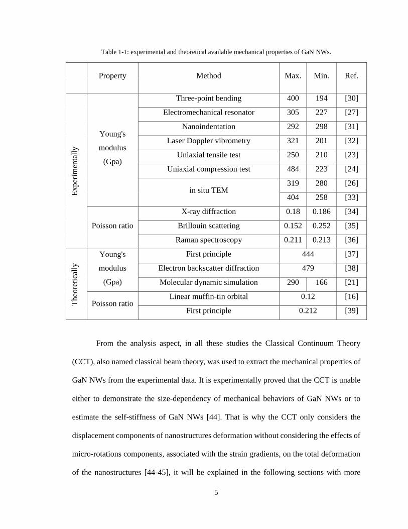
Table 1-1 shows the results of the earlier studies in determining the Young’s
modulus and the Poisson’s ratio of GaN NWs. As it can be seen, the reported values are
very dispersing. This inconsistency can be explained by scrutinizing the experiments and
theoretical analysis used to extract the mechanical properties of GaN NWs. From the
experiments aspect, for example, in the uniaxial compression tests, the tensile tests, the
three point-bending tests, and nanoindentation tests, the nanostructures are in contact with
elastic substrates whose deformations cannot be ignored in some extends [40-42]. The
deformations of the substrates change the boundary conditions resulting to overestimate
the true value of the nanostructures deformations. Furthermore, in these experiments,
regardless of the difficulties of preparing the samples, the GaN NWs need being transferred
and welded on a MEMS-/NEMS-based device or a trench, that can change the mechanical
properties of GaN NWs due to contaminations and partial fractures of GaN NWs during
preparation processes [43].
5
Table 1-1: experimental and theoretical available mechanical properties of GaN NWs.
Property Method Max. Min. Ref. E
xper
imen
tall
y
Young's
modulus
(Gpa)
Three-point bending 400 194 [30]
Electromechanical resonator 305 227 [27]
Nanoindentation 292 298 [31]
Laser Doppler vibrometry 321 201 [32]
Uniaxial tensile test 250 210 [23]
Uniaxial compression test 484 223 [24]
in situ TEM 319 280 [26]
404 258 [33]
Poisson ratio
X-ray diffraction 0.18 0.186 [34]
Brillouin scattering 0.152 0.252 [35]
Raman spectroscopy 0.211 0.213 [36]
Theo
reti
call
y
Young's
modulus
(Gpa)
First principle 444 [37]
Electron backscatter diffraction 479 [38]
Molecular dynamic simulation 290 166 [21]
Poisson ratio Linear muffin-tin orbital 0.12 [16]
First principle 0.212 [39]
From the analysis aspect, in all these studies the Classical Continuum Theory
(CCT), also named classical beam theory, was used to extract the mechanical properties of
GaN NWs from the experimental data. It is experimentally proved that the CCT is unable
either to demonstrate the size-dependency of mechanical behaviors of GaN NWs or to
estimate the self-stiffness of GaN NWs [44]. That is why the CCT only considers the
displacement components of nanostructures deformation without considering the effects of
micro-rotations components, associated with the strain gradients, on the total deformation
of the nanostructures [44-45], it will be explained in the following sections with more

6
details. To take these micro-rotations into account, the non-classical continuum mechanics
theories, like modified couple stress theory (MCST) and modified strain gradient theory
(MSGT), have been introduced and developed by several researchers [46-48]. In these
theories beside the classical materials constants, related to the displacement components,
additional material parameters, related to the micro-rotation components, are appearing
which enable the theory to demonstrate the size-dependency behaviors of nanostructures.
3- Experimental techniques
Techniques used to estimate the mechanical properties of GaN nanostructures differ
from each other based on the desired mechanical properties and the platforms used for the
characterization. Due to the small dimensions of nanostructures, all characterization
techniques were conducted in one of the following types of microscopes: Atomic Force
Microscope (AFM), Scanning Electron Microscope (SEM), and Transmission Electron
Microscope (TEM). Here, we categorize and review the existing techniques for
characterization of mechanical properties of nanostructures from the literatures based on
their loading modes and the required equipment.
3-1- Bending
The most common tools for conducting the bending tests are TEM, SEM and AFM.
Any bending test requires the NWs to be prepared either as cantilever, one free end and
one fixed end, then applying a lateral force on the free end, or as clamped-clamped NWs,
then applying a bending force at any point along the nanostructure. Bending of a cantilever
NW is more popular test because of its simplicity; however, it carries a vast amount of

7
attentions. Nanostructures that epitaxially grown/etched down are perpendicular to the
substrate, one end of the NWs has been fixed at the substrate, the experiment can be easily
conducted through applying a lateral force perpendicular to the nanostructure axis at the
free end of the nanostructure using an AFM/indenter probe [43, 49]. The bending tests can
also be conducted in TEM and SEM using special sample holders equipped with AFM
indenter systems.
TEM and SEM provide the real-time high-resolution images enabling direct
observation of the nanostructure deformation process to understand the deformation
mechanisms of nanostructures, in addition to providing the force-displacement curve
usable for predicting the mechanical properties of NWs. Noted, the TEM has more
advantages over the SEM method because of the higher resolution images; however, TEM
needs ultrahigh vacuum that may damage the surface of nanostructures. Furthermore, some
bending tests using SEM do not provide any force-displacement curve but the quantitative
strength and strain values of nanostructure at fracture can still be calculated.
3-2- In Situ Resonance
The resonance method was first used to characterize the mechanical properties of
multi-walled carbon nanotubes and has been applied to other semiconductors
nanostructures. In the resonance method, a single cantilever NW is excited by alternating
current, AC current. The AC current forces the cantilever NW to resonate at its natural
frequency. The method can be used either in TEM or SEM with a specific conductive
TEM/SEM specimen holder that delivers the electrical current signals between the tip, to

8
which the NWs are mounted, and a counter electrode to generate a fluctuating electrical
field applying an electrodynamic force to the NW [50].
A sharp tip, usually tungsten tip, is swept against NWs so that some nanostructures
from the substrate stick to the tip. The tip is then loaded onto the especial TEM/SEM
specimen holder with electrical connection to the tip and a counter electrode and moved
precisely to position an individual NW very close to the counter electrode. Applying a
tunable AC current across the tungsten tip, where the NW is stuck, and the counter
electrode will drive the NW to vibrate mechanically, from which the natural resonant
frequency is measured. Noted, the frequency–amplitude relationship determines the
resonance frequency. That is why the frequency of the driving voltage is equal to the
resonant frequency, at which the NW resonates with the largest amplitude. According to
the solid mechanic theories, the resonance frequency of the NW depends on the elastic
modulus of the nanostructure. It is worthy to be mentioned that the in situ TEM electric-
field-induced resonance method can be easily used to investigate the fatigue behavior of
NWs as well [51].
3-3- Uniaxial loading
Characterization of the mechanical properties of NWs can also be accomplished by
uniaxial tension or compression loading of a single NW in either TEM or SEM. Tensile
tests in SEM requires a NW to be clamped on the tungsten tip of a nanomanipulator at one
end and the other end to be fixed on an AFM cantilever using different techniques, such as
electron-beam-induced deposition (EBID) or focused ion beam (FIB) implementation. The
AFM cantilever works as the load sensor during the measurement while a tensile force is

9
applied to the NW through the precision movement of the nanomanipulator. The results of
this measurement are stress–strain curves, from which the Young’s modulus, fracture
strength, elastic strain, yield strength and ductility of individual NWs can be predicted.
Similar to the uniaxial tensile test, the same experimental setup can be utilized for
compression tests of individual NWs in SEM while the nanomanipulator moves precisely
toward the AFM cantilever in the opposite direction to apply compressive load to the NWs.
However, the uniaxial compression tests are mainly done using a nano-indenter to
compress the NWs. The uniaxial compression test cannot be performed for high aspect
ratios, length to diameter ratio, NWs because of high chance of buckling. However, this
method makes it possible to measure critical buckling load of the NW as well [52-53].
Deforming an NW in SEM using an AFM probe or nanomanipulator enables direct
real-time observation of the structural changes during the entire process of the NW
deformation. The large chamber size in SEM makes it easy to manipulate the NW
deformation processes. However, it is difficult to reveal the deformation mechanisms of
NWs during In Situ testing in SEM because of the poor structural resolution of SEM. This
problem can be overcome by conducting In Situ experiments in TEM.
3-4- Nanoindentation
One of the most popular methods for the investigation of mechanical properties of
nanomaterials, especially thin films, is nanoindentation. In this method, an indenter, whose
tip radius is few nanometers, is pushed into a nanostructure. The results are the applied
force vs. the penetration depth which can be easily used to estimate the Young’s modulus
and hardness, the resistance to permanent or plastic deformation, of the nanostructures. For

10
nanoindentation of individual NWs, it is necessary to firmly fix the NW to avoid any
movements. To do so, an NW is lying flat on the substrate, and both ends of the NW are
fixed on the substrate usually by EBID. Nanoindentation can be done either using an AFM
tip or an especial indentation tools to perform indentation. The indenter must be much
stiffer than the nanostructure, both substrate and thin film or NW, to prevent any possible
errors due to local deformation of the indenter. Cares must be taken especially in the case
of nanoindentation of NWs with a conical indenter. That is why the indenters are likely to
slip and apply friction between the indenter tip and the NW surface during the indentation
because the indenter rarely can be perpendicular to the surface of circular-shaped NWs.
This issue can be solved by utilizing a Berkovich (three-sided pyramidal diamond) indenter
to perform the imaging and indentations [54].
4- Solid mechanic theories
The CCT provided a fundamental basis for analysis and understanding the mechanical
behavior of materials on macro scale for two centuries by the initial work of Poisson and
Cauchy in 1820s. The CCT uses only displacement components of the nanostructure
deformation without considering the independent rotational components of the
nanostructures. The displacement components of nanostructure deformation, which also
known classical stresses, are related to the external forces using Lame constants, also
named classical parameters. While, the independent rotational components of
nanostructure deformation, which also known as non-classical stresses or couple stresses,
are related to the external forces using length scale, also named non-classical parameter.
Simply said, the CCT is not adequate in capturing any size effect or self-stiffness of

11
nanostructures, since it possesses no characteristic length in the governing equations.
Therefore, it is necessary to resort to higher order continuum theories, such as MCST or
MSGT, which consider the effect of microstructure by including explicit material length
scales in their governing equations. Furthermore, these non-classical solid mechanic
theories can provide a more suitable connection to atomistic models and the fundamental
base for developing size-dependent multi-physics formulations, such as those involving
electromechanical coupling.
A review of the early literature reveals that classical continuum mechanics was based
initially upon an atomistic representation of materials having only central forces within
particles. Equivalently, classical stress and strain components induced by the external
forces, describe the internal forces in the continuum model [55]. However, in a more
realistic representation of materials, it is essential the introduction of non-central forces,
especially when the dimensions are in order of nanometers, in the underlying atomistic
models. This was a motivation for many researchers to consider also the effects of the
gradients of strains, inducing couple-stresses, in the corresponding continuum
representation of the materials.
4-1- Cosserat theory
The Cosserat brothers [45] proposed and formulated different theories for
structural elements in one-dimensional space, such as beams, and two-dimensional space,
such as shells, embedded in three-dimensional space. In these theories, besides the three
independent displacement components, three independent rotational components were
considered to fully determine the deformations of materials, six degrees-of-freedom, at

12
each point. Based upon these successes, the Cosserats then extended this idea of
independent rotational degrees-of-freedoms to the case of a full three-dimensional elastic
medium.
Nowadays, these formulations are referred to as micropolar theories, which attempt
to capture the effect of discontinuous microstructure by considering a continuous
microrotation in addition to the translational degrees-of-freedom. The concept of
independent rotational degrees-of-freedom may also originate from the discrete model of
material in molecular point of view. In molecular view, because we are only dealing with
one particle, the lumped part of matter can be modeled as rigid bodies, which is the basis
of molecular dynamic simulations. In this point of view, the motion of each part can be
described by motion of its center of mass and its rotation. In rigid body dynamics, this
rotation is independent of the motion of the center of mass [56].
Therefore, describing the translation and rotation of individual particles, such as
atoms, molecules and grains, requires discrete point functions. However, in a continuum
representation of mechanical behavior of materials, it is assumed that material is
continuously distributed in space. As a result, the deformation of the body is represented
by the continuous displacement field without considering the discontinuous microstructure
of material and motion of individual particles, which has been shown to be inconsistent
with experimental works.
4-2- Couple stress theory (MTK model)
Some researchers, such as Mindlin and Tiersten [57], and Koiter [58], believed that
the continuous displacement field components are the basis to determine the kinematical

13
quantities and measures of deformation. Therefore, they speculated that in a consistent
continuum theory, the deformation is completely specified by the continuous displacement
field. It should be mentioned, in Mindlin-Tiersten-Koiter (MTK) theory, the rigid body
motion of the infinitesimal element of material at each point of the continuum is described
by six degrees of freedom (i.e., three translational and three rotational). As a result, energy
considerations show that higher order measures of deformation must be related to the
rotation field.
The main problem in this development is the inconsistency of the boundary
condition for the normal component of the moment traction. That is why the right-hand
side of the principle virtual work shows that the boundary conditions on the surface of the
body can be either displacement vector or rotation vector as essential (geometrical)
boundary conditions, or stress and couple stress components as natural boundary
conditions [56]. This apparently makes a total number of six boundary values for either
case. Consequently, there is no other possible type of boundary condition in size-dependent
couple stress continuum mechanics.
However, this contrasts with the number of geometric boundary conditions that can
be imposed [58]. This shows that a material in couple stress theory does not support
independent distributions of normal surface moment (or twisting) traction, and the number
of mechanical boundary conditions also is five. This result was first established by [58]
although his couple stress theory does not satisfy this requirement.

14
4-3- Modified couple stress theory (YCLT model)
After development of MTK theory, some researchers, such as Yang et al. [59],
managed to develop a model of couple stress that results in a symmetric couple stress
tensor. To do so, they considered an additional equilibrium equation for the moment of
couple stresses associated with the two equilibrium equations of the classical continuum.
Application of this equilibrium equation leads the curvature tensor to be deviatoric, and
thus is specified only by five independent components. Therefore, in this model, which
called MCST, all the inconsistencies in MTK theory, such as the indeterminacy in the
couple-stress tensor, remain intact.
Interestingly, the stress-strain tensor and the final governing equilibrium equations
are similar to those in MTK theory for isotropic material. Regardless of this fact that the
MCST inherits all inconsistencies from indeterminate MTK theory, it has been widely
attracted attentions in many literatures, because the appearance of only one length scale
parameter for isotropic material makes the MCST more desirable from an experimental
and analytical view [56]. As a result, this theory has been extensively used in many
problems, such as bending, buckling and post-buckling, and vibration in recent years to
investigate the mechanical behaviors of the nanostructures [60-61]. It is noteworthy to be
mentioned that the MCST cannot be taken as a special case of indeterminate MTK theory.
This is obvious by noticing that this similarity is only valid for isotropic material, and there
is no simple analogy for general anisotropic and bi-anisotropic cases.

15
4-4- Modified strain gradient theories
In 1965, Mindlin [62] proposed a higher-order gradient theory for elastic materials
by considering the higher derivatives of the strain tensor, from first up to third derivatives,
in definition of energy. [62-64] used Mindlin’s formulations by considering only the first
derivative of the strain tensor and called it the strain gradient theory. In comparison with
the couple stress theory, the strain gradient theory contains some additional higher-order
stress components beside the classical and couple stresses. Indeed, the couple stress theory
is a special case of the strain gradient theory.
In a similar way utilized by Yang et al. [59] for the MCST, Lam et al. [65]
introduced a MSGT, which reduces in a special case to the MCST. Henceforth, when the
strain gradient theory is used in the text, it denotes the version of the theory presented by
Lam et al. [65]. The strain gradient theory is employed to formulate the static and dynamic
behaviors of linear and nonlinear elastic beams, both the Euler-Bernoulli and the
Timoshenko models, shells and bars under torsional loading. In addition, the size-
dependent functionally graded beam models have been developed by Kahrobaiyan,
Asghari, Rahaeifard, and Ahmadian [66] based on the strain gradient theory. Furthermore,
this non-classical theory is utilized by Akgoz and Civalek [67] to study the buckling of
microbeams under uniaxial compression loadings.

16
Chapter 2: Modified Couple Stress Theory
1- Introduction
In this chapter, a rigorous method for deriving the MCST’s governing equations for
GaN NWs is provided. The MCST governing equations can be derived based on either
energy principle or equilibrium method [46, 48, 59-60]. The procedure presented here is a
simplified version of earlier works [48, 59], where they derived the MCST’s governing
equations based on the energy principal theory. After rederivation of the MCST’s
governing equations, the governing equations were solved according to the loading and
boundary conditions of the GaN NWs to derive the relationship between the deflection and
applied force for each individual the GaN NWs.
2- The MCST for elasticity
The modified couple stress theory was presented by Yang et al. [59], in which the
both strain tensor (conjugated with classical stresses) and curvature tensor (conjugated with
couple stresses or non-classical stresses) were considered in the total strain energy density
function. Therefore, the total strain energy, U , for a deformed isotropic linear elastic body
occupying region is given by
3,2,1,2
1jidvmU ijijijij
(1)
with the stress tensor, ij , strain tensor, ij , deviatoric part of the couple stress tensor, ijm
, and symmetric curvature tensor, ij , are, respectively, defined by

17
ijijij Itr 2 (2)
T
iiij uu 2
1
(3)
ijij lm 22 (4)
T
iiij 2
1
(5)
where and being Lame’s constants, l a material length scale parameter, iu the
components of displacement vector and i the components of rotation vector given by
)(2
1ii ucurl
(6)
Obviously, both ij and ijm , as respectively defined in Eqs. (2) and (4), are
symmetric, with T
ijij and T
ijij mm due to the symmetry of strain tensor and curvature
tensor, ij and ij , given in Eqs. (3) and (5), respectively. The additional parameter l is
regarded as a material property characterizing the effect of couple stresses initiated due to
the micro-rotations.
3- Structural and Dynamical models of NWs based on MCST
The Cartesian axes for plane NW analysis are established, as shown in figure 2-1.
The origin is placed at the bottom section. The total length of the NW was assumed to be
L . As it will be shown in the following chapters, chapter 4, the GaN NWs have high aspect
ratios, length to diameter ratio. Thus, the GaN NWs can be considered as Bernoulli-Euler
beams.

18
Figure 2-1: schematic picture of deformed GaN NWs under a general loading.
According to the basic hypotheses of the Bernoulli-Euler beams and the one-dimensional
beam theory, the displacement field at each point of the GaN NWs can be written as
where u , , w are the x , y , and z components of the displacement vector, and
)(x is the rotation angle of the centroidal axis of the NWs. For infinitesimal
deformations, the rotation angle of the NWs can be approximated by
x
txwx
),()(
(8)
From Eqs. (3), (7) and (8), one can obtain
2
2 ),(
x
txwzxx
(9)
),(0, txwwtxzu (7)
z
x
q(x)
L
0
2r
Cross-section

19
0 zxyzxyzzyy
And from Eqs. (6) to (8), it follows that
0),(
zxy
x
txw
(10)
The substituting Eq. (10) into Eq. (5) results in
0),(
2
12
2
yzxzzzyyxxxy
x
txw
(11)
For a slender NW with a large aspect ratio, the Poisson’s effect can be ignored to
simplify the formulation of beam theory for the NW. Therefore, inserting Ep. (9) into Eq.
(2), yields
where E , v are respectively Young’s modulus and the Poisson’s ratio of the GaN NW.
Similarly, the substitution of Eq. (11) into Eq. (4) leads to
02
22
xzyzzzyyxxxy mmmmm
x
wlm
(13)
where is the shear modulus defined as v
E
12 . Using Eqs. (9), (11), (12) and (13)
in Eq. (1) gives
where I is the second moment of the cross-sectional and A is the area of the cross-
sectional of the GaN NW. On the other hand, the work done by the external forces in the
most general form of loading ),( txq , as shown in figure 2-1, is
02
2
xyxzyzzzyyxx
x
wEz
(12)
L
dxx
wAlEIU
0
2
2
22
2
1 (14)

20
On the other hand, the kinetic energy can be defined as
L
dxt
txwxAxT
0
2),(
)()(2
1
(16)
where )(x is the density of the GaN NWs. At this point, the Hamilton’s principle can be
used to determine the dynamic governing equations of GaN NWs in the scope of MCST as
well as all possible boundary conditions as follows
Inserting Eqs. (14)- (16) into Eq. (17) gives
02
1
2
12
1 0
222
t
t
L
dxdtqwwAlEIwA (18)
Where the Lagrange’s function is
where
2
2 ),(),(),(
x
txww
x
txww
t
txww
(20)
Implementing the calculus of variations, Eq. (18) can be expanded as
L
dxtxwtxqV0
),(),( (15)
02
1
t
tdtUVT
(17)
qwwAlEIwAF 222
2
1
2
1
(19)

21
Lt
t
t
t
L
t
t
L
t
t
L
t
t
L
dxww
Fdtw
w
Fw
w
F
x
dtwdxw
F
tw
F
w
F
x
dxdtwwwF
dxdtqwwAlEIwA
00
0 2
2
0
0
222
2
1
2
1
2
1
2
1
2
1
),,(
2
1
2
1
(21)
Substituting Eq. (19) into Eq. (21), the variational equation (21) takes the form
where
2
2
3
3)3(
4
4)4(
t
ww
x
ww
x
ww
(23)
In view of the Eq. (22), the dynamic governing equation of the NW in terms of ),( txw is
given by
the initial conditions as
0),(),(),(),( 1122 txwtxwtxwtxw (25)
and the equations
prescribed at 0x and Lx as the boundary conditions.
00
0
2
0
)3(2
0
)4(2
2
1
2
1
2
1
2
1
L t
t
t
t
L
t
t
Lt
t
L
dxwwdtwwAlEI
dtwwAlEIdtwdxqwAwAlEI
(22)
qwAlEIwwA )4(2)4( (24)
Lx
Lx
LxLx
worx
w
x
wor
x
w
,0
,0
3
3
,0,0
2
2
0
0
(26)

22
It can be seen from Eq. (24) that the governing equation of the NWs has two parts:
one related to A and EI as in CCT and the other related to 2Al . Moreover, it should
be emphasized that the MCST contains only one additional material constants besides two
classical material parameters. Nevertheless, the presence of l enables the incorporation of
the GaN size features in the MCST and renders it possible to explain the size-effects of
GaN NWs by taking into account the micro-rotations, couple stresses. It must be noted,
letting 0l , the MCST will reduce to the CCT.
4- Analysis of the GaN NWs using MCST
During the experiment, I applied a lateral infinitesimal deflection on the free end of
the GaN NWs using AFM’s tip while I was monitoring the normal deflection of the AFM’s
tip during loading and unloading cycles. Figure 2-2 shows the loading condition on each
GaN NW in contact with the AFM’s tip.
Figure 2-2: GaN NWs under loading.
23
The AFM’s tip applies an axial force and a lateral force on the free end of the GaN NW.
The moment equilibrium condition at any cross-section along the GaN NW can be written
as
)()()(0 0 wwNxLFxMM (27)
where 0w , F , N and L are the maximum deflection at the free end of the GaN NW,
0wwLx
, the lateral force, the normal force and the length of the nanowire, respectively.
The total moment at each cross-section can be related to the deflection of the GaN NW as
It should be emphasized that the distributed force, )(xq , is zero in this case because the
AFM tip only touches the free end of each GaN NW. Furthermore, all partial derivatives
respect to time are zero because the loading is stationary. Therefore, it gives
)(02
22 xLFNwNw
dx
wdAlEI
(29)
Here, I have second-order nonhomogeneous linear differential equation. Therefore,
the solution of this equation is summation of its both solutions, general solution, gw , and
particular solution, pw . The general solution can be easily defined by considering the right-
hand side of the above equation equal zero as follows
And the particular solution will be obtained as
)(0 xLN
Fwwp
(31)
2
22
dx
wdAlEIM
(28)
)cos()sin( kxbkxawg (30)

24
Therefore,
where k is the square root of the normal force to the rigidity of the nanowire ratio,
2AlEINk
.
The unknown coefficients, a , b and 0w , can be determined using the boundary
conditions. I assumed clamped boundary conditions, at the fixed end since the contact
between the GaN NWs and the substrate is covalent type GaN-GaN bonds. Consequently,
the NWs and the substrate are perfectly lattice matched, and there are not any stress
concentrations at the fixed end. Furthermore, the SEM images were taken from a GaN NW
while a nanomanipulator, also called omniprobe, was bending the GaN NW, figure 2-3.
Figure 2-3 shows a strong connection between the substrate and the GaN NWs in the which
validates the clamped boundary condition.
Figure 2-3: validating the clamped boundary conditions of the GaN NWs.
)()cos()sin()( 0 xLN
Fwkxbkxawwxw pg
(32)
Nanomanipulator
GaN NWs

25
Therefore, the clamped boundary conditions at the fixed end are
0
0
0
0
x
x
dx
dw
w
(34)
Furthermore, since we assumed 0w to be the maximum deflection at the free end of GaN
NWs, therefore
0wwLx
(35)
Applying the above boundary conditions to the solution of the governing equation and
simplifying the result is
In the above equation, we have the lateral force and normal force exerting on the
nanowires while the AFM gives us only the normal force, equivalently, the normal
deflection of the AFM’s tip. However, one can easily find this ratio by considering the
equilibrium conditions for the AFM’s tip during the loading and unloading, for more
information see chapter 5.
L
k
kL
N
Fw
)tan(0
(36)

26
Chapter 3: Strain Gradient Theory
1- Introduction
In this chapter, a rigorous method for deriving the governing equations of the
MSGT based on energy principle theory is presented. More details about the procedure for
deriving the governing equations can be found in [65, 68-69]. After the rederiving the
governing equations for MSGT, I solved the governing equation for the case of GaN NWs
to derive the relationship between the deflection and force for each individual GaN NWs.
2- The MSGT for elasticity
A new version of the MSGT was proposed by Lam et al. [65], in which a new
additional equilibrium equation to predict the behavior of higher-order stresses, the
equilibrium of moments of couples, are introduced in additional to the classical equilibrium
equations of forces and moments of forces [68]. In the governing equations of this theory,
there are three independent higher-order materials length scale parameters associated with
the higher strain gradients in addition to two classical material parameters for isotropic
linear elastic materials. Then the total strain energy, U , of a deformable isotropic linear
elastic material occupying region is given by
where the classical strain tensor and the higher gradients of the strain tensor are defined as
follows,
dmpU s
ij
s
ijijkijkiiijij
)1()1(
2
1
(1)

27
ijjiij uu (2)
mmiiimm , (3)
mjmmmjkimimmmijk
mkmmmkijijkkijjkiijk
2215
1
215
1
3
1)1(
(4)
qipjpqqjpipq
s
ij ee 2
1
(5)
where i is differential operator, iu is the displacement vector, ij is the classical strain
tensor, imm, is the dilatation gradient vector, )1(
ijk is the deviatoric stretch gradient tensor,
s
ij is the symmetric rotation gradient tensor, ij and ijke are the Knocker delta and the
alternate tensor. It should be mentioned, in the above and in subsequent equations, the
index notation will be used with repeated indices rendering summation from 1 to 3.
Moreover, the corresponding classical and non-classical stress tensors are defined as
follows
ijmmijij k 2 (6)
ii lp 2
02 (7)
)1(2
1
)1( 2 ijkijk l (8)
s
ij
s
ij lm 2
22 (9)
where ij is deviatoric strain tensor introduced as
ijmmijij 3
1
(10)

28
where k and are bulk and shear module, respectively, and 0l , 1l , 2l are additional
independent material parameters associated with dilatation gradients, deviatoric stretch
gradients and rotation gradient for the GaN NWs, respectively.
3- Structural and dynamical models of NWs based on MSGT
According to the energy principle theory, the governing equation of a NW under
any general form of loading as well as all boundary conditions can be determined with the
aid of a variational principle [46]
where U is the total strain energy and W is the total work done by external forces and
indicates variation. Figure 3-1 shows an uniform GaN NW, which is subjected to a general
loading distribution, )(xq , along its longitudinal axis x . Hence, the loading plane
coincides with the xz plane, and the cross-section of the beam parallel to the yz plane.
Figure 3-1: a NW under general form of lateral force.
0WU (11)
z
x
q(x
)
L
0
2r
Cross-section

29
Similar to the previous section, because the aspect ratios, length to diameter ratio,
of GaN NWs are large, we can model them as Bernoulli-Euler beam. According to the
Bernoulli-Euler hypothesis and the one-dimensional beam theory, the displacement field
of a GaN NW in bending can be written as
where u , v , w , are the x , y , and z components of the displacement vector,
respectively. Inserting Eq. (12) into Eq. (2), then the classical strain tensor can be
determined, where the only non-zero strain component is
2
2
x
wzxx
(13)
And from Eqs. (2) and (3) it follows that
By using Eq. (2) in Eq. (5) gives the stretch gradient tensor, where the only non-zero stretch
gradients, s
ij , components are
2
2
2
1
x
ws
yx
s
xy
(15)
)(0)(
xwwvx
xwzu
(12)
2
2
3
3
0x
w
x
wz zyx
(14)

30
By substituting Eq. (2) into Eq. (4), the non-zero dilatation gradients, )1(
ijk , can be found as
It can be concluded from Eq. (10) and (13) that
xxzzyyxxxx 3
1
3
2
(17)
For a slender beam with a large aspect ratio, the Poisson effect is secondary and
may be neglected to facilitate the formulation of a simple beam theory. By considering
0 , as was done in CCT, inserting Eqs. (13) and (17) into Eq. (6) then gives the non-
zero classical stresses ij as
2
2
x
wEzE xxxx
(18)
The use of Eq. (14) in Eq. (7) gives
2
22
03
32
0 202x
wlpp
x
wzlp zyx
(19)
and by inserting Eq. (15) into Eq. (9), the only non-zero higher-order stress s
ijm is
2
22
22
22
22
12
x
wl
x
wlmm s
xy
s
ij
(20)
2
2)1(
3333
3)1(
3312
2)1(
3223
3)1(
313
2
2)1(
1112
2)1(
2322
2)1(
223
3
3)1(
1113
3)1(
2123
3)1(
133
3
3)1(
1222
2)1(
1133
3)1(
111
5
1
5
1
15
1
5
1
15
4
15
1
15
1
5
1
5
1
5
1
5
1
15
4
5
2
x
w
x
wz
x
w
x
wz
x
w
x
w
x
w
x
wz
x
wz
x
wz
x
wz
x
w
x
wz
(16)

31
Similarly, from Eqs. (16) and (8), the non-zero higher-order stresses )1(
ijk are
Substituting Eqs. (13) - (15), (16), (19), (21) into Eq. (1), the following expression can be
achieved for the total strain energy U
L
wKwSU0
2)3(2..
2
1
(22)
where
and I is the inertia moment of the cross-section and A is the area of the cross section of
the GaN NW.
Taking the first variation of Eq. (22) results in, together with Eq. (23)
LL
L
L
L
ww
Fw
w
F
dx
d
w
F
ww
F
dx
d
w
F
dx
dwdx
w
F
dx
d
w
F
dx
d
dxwwFU
0
)3(
0
)3(
0
)3(2
2
0 )3(3
3
2
2
0
)3(,
(24)
2
22
1
)1(
3333
32
1
)1(
3312
22
1
)1(
3223
32
1
)1(
313
2
22
1
)1(
1112
22
1
)1(
2322
22
1
)1(
223
3
32
1
)1(
1113
32
1
)1(
2123
32
1
)1(
133
3
32
1
)1(
1222
22
1
)1(
1133
32
1
)1(
111
5
2
5
2
15
2
5
2
15
8
15
2
15
2
5
2
5
2
5
2
5
2
15
8
5
4
x
wl
x
wzl
x
wl
x
wzl
x
wl
x
wl
x
wl
x
wzl
x
wzl
x
wzl
x
wzl
x
wl
x
wzl
(21)
3
3)3(
2
2
2
2
2
1
2
0
2
1
2
0225
432
5
42
x
ww
x
ww
AlAlAlEISllIK
(23)

32
where, the Lagrangian function, F , is
Eqs. (24) and (25) can be utilized to represent the variation of the total strain energy of the
GaN NWs as
LLLL
wwKwwKwSwwKwSwdxwKwSU0
)3(
0
)4(
0
)5()3(
0
)6()4( ....... (26)
where
On the other hand, the variation of the work done by the external forces, )(xq , the
boundary shear force, V , and the boundary classical and non-classical bending moments,
M and hM , respectively, reads
LhLLL
wMwMwVdxxwxqV 0000
)()( (28)
In view of Eqs. (26) and (28), the variational form of Eq. (11) takes the form
The above variational equation implies that each term must be equal to zeros. Hence, the
governing equation of the GaN NWs in bending is given by
0.. )6()4( qwKwS (30)
while the boundary conditions must satisfy the following equations
2)3(2 .).(2
1wKwSF
(25)
6
6)6(
5
5)5(
4
4)4(
x
ww
x
ww
x
ww
x
ww
(27)
0...
....
0
)3(
0
)4(
0
)5()3(
0
)6()4(
LhL
LL
wMwKwMwKwS
wVwKwSwdxqwKwSVU
(29)

33
0)0()0(.)0()()(.)(
0)0()0(.)0(.)0()()(.)(.)(
0)0()0(.)0(.)0()()(.)(.)(
)3()3(
)4()4(
)3()5()3()5(
wwKMLwLwKLM
wwSwKMLwLwSLwKLM
wwSwKVLwLwSLwKLV
hh
(31)
For boundary conditions, if one assumes the four classical boundary conditions to
be )0(w , )(Lw , )0(w and )(Lw prescribed and the corresponding non-classical ones to
be )0(w and )(Lw prescribed, then 0)()0( Lww , 0)()0( Lww ,
0)()0( Lww and Eq. (31) are all satisfied. In virtue of Eq. (31), one can get that,
when dealing with the classical boundary conditions, either the deflection w or the
boundary shear forces )3()5( SwKwV and the strain, w , or the boundary classical
bending moments )4(KwwSM at the boundaries of the beam must be specified. For
the case of the non-classical boundary conditions, one must specify either the boundary
strain gradient, w , or the non-classical boundary moments as )3(KwM h .
It should be mentioned, when the higher-order material parameters 0l and 1l equal
to zero, then the constitutive relation reduces to that of the MCST and the corresponding
governing equation reads
There results conform to solutions based on the MCST [48]. Moreover, when all three
higher-order material parameters, e.g. 0l , 1l , 2l , equal to zero, then the constitutive relation
reduces to that of the CCT.
0)0()0()0()()()(
0)0()0()0()()()(
2
2
2
2
)3(2
2
)3(2
2
wwAlEIMLwLwAlEILM
wwAlEIVLwLwAlEILV
(32)

34
4- Solution for the GaN NWs using MSGT
Before defining the solution of the above equations, we need to determine our
assumptions. Figure 3-2 shows the nanowire under loading during the experiment. The
center of the Cartesian coordinate system is fixed at the clamped end, where the nanowires
are connected to the substrate.
Figure 3-2: schematically showing the deformation of the GaN NWs under loading.
To solve the governing equation of the MSGT, the first assumptions are the steady
state process, static process, therefore, the time derivatives are zero. Furthermore, there is
not any distributed lateral loading, 0xq . Writing the equilibrium condition for the total
moment at any point along the NW reads
)()()(0 0 wwNxLFxMM (33)
35
The total moment at any point is related to the external distributed load as
L L
dxdxxqxM0 0
)()( (34)
which is related to the deflection of the beam as follows
Substituting Eq. (35) into Eq. (30) and rearranging leads to
)(04
4
2
2
xLFNwNwdx
wdK
dx
wdS
(36)
Eq. (36) is a second-order, linear and nonhomogeneous differential equation, which
its solution is summation of the general solution, gw , and the particular solution, pw . To
find the general solution, one must consider its homogenous form to determine the
characteristic equation of the differential equation. To do so, since all coefficients are
constants, then I consider the solution as an exponential equation, )exp( x , therefore the
characteristic equation will be found
where J and P are constants equal to S
KJ and S
NP . Noted that both J and P
are positive, which leads in four solutions, two pure real solutions and two pure imaginary
solutions as
J
JPj
J
JP
J
JP
J
JP
2
1410
2
411
2
1410
2
411
2
2
2
1
2
1
(38)
4
4
2
2
0 0)()(
dx
wdK
dx
wdSdxdxxqxM
L L
(35)
024 PJ (37)

36
Therefore, the general solution for Eq. (36) will be
Considering the Eq. (36), the particular solution can be demonstrated as
xLN
Fwxwp 0)(
(40)
Finally, the solution for Eq. (36) determined by summation of Eqs. (39) and (40) solutions
is
xLN
Fwxdxc
xbxaxwxwxw gp
011
22
)cosh()sinh(
)cos()sin()()()(
(41)
The classical and non-classical boundary conditions are
Applying the boundary conditions to the solution equation, the coefficients can be found
as
xdxcxbxaxwg 1122 coshsinhcossin)( (39)
0)(
0)0(
0)0(
)(
0)0(
3
3
3
3
0
Lxdx
wd
xdx
wd
xdx
dw
wLxw
xw
(42)

37
LLH
LLG
LLLL
GLLH
N
F
N
FDd
N
Fc
LLLL
LHGL
N
F
N
FBb
N
Fa
12
2
2
1
2
2
2
122
2
2
1
2
2
2
1
13
11
2
2
2
223
22
2
1
2
1
21
3
221
3
1
2
3
22
3
11
2
2
2
2
21
3
221
3
1
11
3
1
3
22
2
1
2
1
coshcos
sinhsin
sincoshcossinh
sincos
sincoshcossinh
coshsinh
(43)
Substituting Eqs. (43) into Eq. (41), on can achieve
In Eq. (42), the first three boundary conditions are the classical boundary conditions
demonstrating the clamped boundary condition at the fixed end of the GaN NWs. The proof
of the clamped boundary condition of the GaN NWs was provided in figure 2-3 of chapter
2.
00 wN
FLDB
(44)

38
Chapter 4: Theoretical Simulation Using Quantum
Mechanics
1- Introduction
In this chapter, a theoretical method based on quantum mechanics theories for
calculating the lattice dynamic matrix, or phonon band structure, has been provided to
predict the mechanical properties of GaN NWs theoretically. In the first section, I explained
the method for deriving the lattice dynamic matrix based on the solid mechanics
framework, more details for this part can be found at [70-71]. Then, a brief explanation of
deriving the dynamic matrix based on quantum mechanics theories is provided, more
details for this part can be found at [71-72].
2- Lattice dynamic matrix based on solid mechanics
According to the linearized theory of a homogeneous elastic medium and
considering the gradients of strains, a general form of the Lagrangian density, , for a
solid can be written as follows [71]
...2
1
2
1,
2
,,
1
,, lmnkijijklmnmnljkiijklmnlmkjiijklmklijijklii uFuuFuuDCuu (1)
where is the density, the ratio of the mass to volume, of the GaN, u is the displacement
vector, the dot on top of displacement components stands for differentiation with respect
to time and the comma stands for differentiation with respect to the spatial variables in the
reference coordinate. The first term in the expression of the potential energy is due to the

39
long-wavelength elastic excitations of the solid, equivalently, the lowest-order description
of sound wave propagation in the medium, which is GaN here.
Therefore, ijklC is the stiffness matrix defined in the CCT. In the bulk scales, the
long-wavelength elastic excitations of the solid are the dominant terms in the potential
energy while the higher-order strain gradients represented by non-classical terms, D , 1F
and 2F , have a negligible contribution on the potential energy. However, in the nanoscales,
where the strain gradients are comparable with dimensions of the nanostructure, the non-
classical terms have significant effects. Lastly, ε is the strain tensor obtained using
Tuuε
2
1 (2)
It is noteworthy to be mentioned that the Lagrangian density consists of the total
kinetic energy and the potential energy, the first term shows the kinetic energy and the
remaining terms are the potential energy. The potential energy density is invariant in the
Euclidean group transforming. That is why the internal energy density only depends on the
first- and higher-order derivatives of the displacement, not only on the displacement
components. Invariance condition under the rigid rotations disregard the contribution of
the asymmetric part of the strains and strain gradients on the internal energy density [71].
In order to derive the dynamical matrix of the GaN, one can use the variational
analysis as demonstrated in [70]. Therefore, applying the variational principle leads to

40
...
2
1
,0
,,,,
1
,,,,
1
,,,,,,,,
jimnkmnkjliijklmnjilmnklmnkjiijklmn
jilmklmklkijklmjilklkjiijkl
uuuuFuuuuF
uuuuDuuuuCuu
dtdx
dxdt
(3)
Implementing the integral by part technique onto Eq. (3), the dynamic governing equation
can be obtained as
...,,, lmnjkijklmnlmjkijklmljkijkli ufuducu (4)
To derive Eq. (4) from Eq. (3), the following constrains were applied.
12
,,,,
,,,
,,
ijklmnijklmnnmljkiijklmn
ijklmmljkiijklm
ijklljkiijkl
FFsymsymf
Dsymasymd
Csymsymc
(5)
where sym and asym symbols represent the symmetric and asymmetric parts of the elastic
constant tensors respect to the indices mentioned as subscripts.
It should be emphasized that the fifth-order tensor d in Eq. (5) demonstrates an
interesting phenomenon in the solid, named Acoustic Activity. The acoustic activities
inside a solid are the same as the well-known phenomenon of optical activities which
describe the effect of spatial dispersion on the propagation of an electromagnetic wave.
The optical activities mainly contribute to first-order dispersive contributions to the
dielectric constant tensor which is usually a function of the frequency only without
dependency on the wave-vector [70]. In the optical activities, the dispersive effects can be
fully explained by considering an invoking non-local dependence of the electric
displacement vector D in an electric field, E . The same concept is also valid for the

41
acoustic activity in a solid. The fifth-order elastic tensor d in this description, is similar to
the gyroscopic tensor in the optical activity, that it provides a first-order wave-vector
dependence to the elastic tensor.
Eventually, to derive the lattice dynamic matrix, one can consider propagation of a
plane-wave in the medium, with solution of the form of k.ritiuu ii exp0 , which
results in
002 ... knmljijklmnmljijklmljijkli ukkkkfkkkidkkcu (6)
where the dynamic matrix, )(kR , is defined as
...)( nmljijklmnmljijklmljijkl kkkkfkkkidkkckR (7)
Using the lattice dynamic matrix, one can easily calculate the phonon dispersion relations,
which express the acoustic and optical frequencies in terms of wave-vector, for GaN. To
do so, the eigenvalues of the equation must be calculated.
It is noteworthy to be mentioned that Eq. (7) renders the general form of the lattice
dynamic matrix for a linear body. If one neglects the non-classical terms, the lattice
dynamical matrix reduces to the CCT definition of the lattice dynamic matrix which is
ljijkl kkc . Furthermore, to derive the non-classical properties of the GaN NWs according to
the MCST or MSGT, the appropriate non-classical mechanical properties of the GaN must
be considered and the remaining must be ignored.

42
3- Lattice dynamic matrix based on quantum mechanics
Several approaches for demonstrating the lattice dynamic matrix in the framework
of the quantum mechanics have been proposed over the years, such as density functional
perturbation, density functional theory, ab initio first principle, rigid valence shell model,
rigid ion model, polarizable bond charges model and deformable ion model. Furthermore,
there are some strong software available, such as Quantum ESPRESSO [73] or Atomic
Tool Kit Virtual Nano-Lab (ATK-VNL) [74], that can be used to calculate the lattice
dynamic matrix. In this thesis, I used the ATK-VNL to calculate the lattice dynamic matrix
and phonon band structure of the GaN NWs. Therefore, I focus on linking the lattice
dynamic matrix in the pure framework of the solid mechanics to the lattice dynamic matrix
calculated in the pure quantum mechanics framework.
Comparing with the solid mechanics approach, from the microscopic lattice-
dynamic viewpoint, the lattice dynamic matrix of a crystalline solid including more than
one atom in its unit cell can be defined as [75]
p
pqqp
ikik iKMM
R
XXkk .exp
(8)
where M and M are the masses of the -th and -th atoms, respectively. Furthermore,
qp
ikK , qX and pX are the atomic force constant matrixes, the position of the atom in
q -th unit cell and the position of the atom in p -th unit cell, respectively. The long-
wavelength limit ( 0k ) of Eq. (8) can be obtained by expanding )(kR in powers of k
until the first non-vanishing term to appear as

43
ljijkl kkcR )(k (9)
where the tensor c can be found as
n
b
mn
a
mnmn
ikijkl Kc XXXX02
1 (10)
The constants ijklc have the same symmetry as the elastic constants ijklc of Eq. (5).
Consequently, they are similar tensors. Regarding to this fact, the solid mechanics is
sometimes referred to as a long-wavelength approximation of lattice-dynamical theory.
Similarly, to identify microscopic material constants which resemble the elastic constants
d and f of Eq. (7), one can easily approximate the equation to higher-orders of k .
However, the identification between the discrete and continuum nature of the
material is not so readily apparent when the crystal lattice ceases to be a Bravais lattice.
Eq. (7) derived in the framework of the solid mechanics includes three governing equations
for demonstrating the mechanical behaviors of a nanostructure in three dimensional spaces.
On the other hand, Eq. (8) derived from a lattice-dynamical point of view includes N3
governing equations, where N is the number of atoms per unit cell. Three solutions to this
eigenvalue problem posed by Eq. (10) correspond to acoustic phonons while the remaining
13 N modes are the optical phonon modes.
4- Block diagonalizing the lattice dynamic matrix
The last step after calculating the lattice dynamic matrix using one of the quantum
mechanics theories is to block diagonalize the lattice dynamic matrix. That is why the
acoustic and optical phonons modes in the dynamic matrix are coupled, which they must

44
be decoupled. More details regarding to the block diagonalizing the lattice dynamic matrix
can be found in [70].
At )0,0,0(k , also named Gamma point, a unitary transformation, U , can be
implemented in order to block diagonalize the lattice dynamical matrix. Applying this
unitary transformation matrix at the Gamma point results in
o
a
TU
D
DURUR
3333
3333
0
0)0()0( kk (11)
where matrices aD 33 and oD 33 are the low frequencies, called acoustic modes, and high
frequencies, called optical modes, respectively, contributions to the lattice dynamical
matrix. The aD 33 is the dynamical matrix derived using the solid mechanics theory.
However, for the case of 0k , applying the same unitary transformation matrix will not
results in a full decoupled transformed matrix, there are acousto-optical coupling modes
which must be decoupled.
333333
333333
)()(
)()()()(
IkIk
IkIkkk
ODO
OODURUR
o
a
TU (12)
This form of the lattice dynamical matrix is only valid if the used quantum mechanics
model is analytical near the Gamma point. This constrain is not valid for the polar crystals
whose Coulombic terms contributing to the lattice dynamical matrix have a macroscopic
field term of the form 2k
kk . However, for a slightly semi-polar and non-polar materials,
the effect of the non-analyticity could be ignored [76]. Therefore, regarding to the
analyticity of the lattice dynamic matrix, it is possible to find an orthogonal transformation
in order to fully decouple the optical and acoustic modes. This well-known orthogonal
transformation is Hermitian matrix. Thus,

45
o
a
U
D
DHiRHi
3333
3333
0
0expexp k (13)
Similar to [70], a perturbative approach can be employed to find H . Moreover, the
transformed lattice dynamic matrix can be approximated using a Taylor series as
0
)(
3333
3333
0
0
j
j
oo
aa
KD
D (14)
where
HHHHHHH
HHH
XXKXKYXYXK
XYXKXXKYKHK
,,12
1,
3
2,,,
2
1
,,2
1,,
2
1,,
)2()2()4(
)3()2()1(
0
)0(
3333
3333
00
00
I
Ik
o
a
U
E
ERH
33
33
33
33
0)(
)(0)(),0(
)(0
0)()(
k
kkk
k
kk
U
oa
U
aoU
U
oo
U
aa
R
RXR
R
RY
(15)

46
Chapter 5: Fabrication and Measurement Methods
1- Introduction
This chapter is designated for explaining the experiment procedures, fabrication
process and measurement method. Three different approaches used to prepare the GaN
NWs were briefly explained; however, the final measurements were done on the last
approach of preparing the GaN NWs. Then the procedure for collecting the data,
characterization of the mechanical properties of the GaN NWs and characterizing the
friction coefficient are meticulously explained.
2- Fabrication methods
Three different approaches were used to prepare the GaN NWs. The first approach was
a top-down approach using Au-nanoparticles, gold nanoparticles, mask followed by
etching processes, a combination of dry and wet etches. The second approach was a
bottom-up selective-area epitaxial growth using metal organic chemical vapor deposition
(MOCVD) followed by etching processes, a combination of dry and wet etches. The third
approach was a top-down approach using nickel (Ni) mask patterned by Interferometer
Laser (IL) method followed by etching processes, a combination of dry and wet etches. For
all the bottom-up and top-down fabricated the GaN NWs were c-plane {0001} and vertical
non-polar {11̅00} m-plane sidewalls.
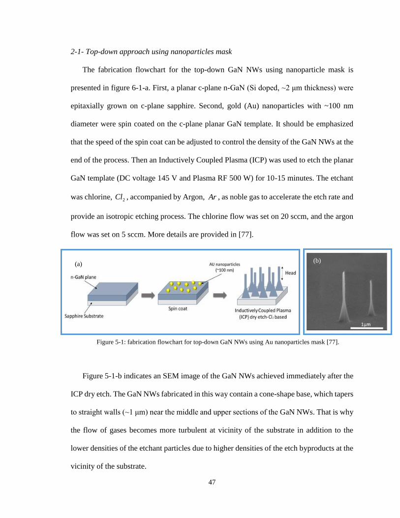
47
2-1- Top-down approach using nanoparticles mask
The fabrication flowchart for the top-down GaN NWs using nanoparticle mask is
presented in figure 6-1-a. First, a planar c-plane n-GaN (Si doped, ~2 μm thickness) were
epitaxially grown on c-plane sapphire. Second, gold (Au) nanoparticles with ~100 nm
diameter were spin coated on the c-plane planar GaN template. It should be emphasized
that the speed of the spin coat can be adjusted to control the density of the GaN NWs at the
end of the process. Then an Inductively Coupled Plasma (ICP) was used to etch the planar
GaN template (DC voltage 145 V and Plasma RF 500 W) for 10-15 minutes. The etchant
was chlorine, 2Cl , accompanied by Argon, Ar , as noble gas to accelerate the etch rate and
provide an isotropic etching process. The chlorine flow was set on 20 sccm, and the argon
flow was set on 5 sccm. More details are provided in [77].
Figure 5-1: fabrication flowchart for top-down GaN NWs using Au nanoparticles mask [77].
Figure 5-1-b indicates an SEM image of the GaN NWs achieved immediately after the
ICP dry etch. The GaN NWs fabricated in this way contain a cone-shape base, which tapers
to straight walls (~1 μm) near the middle and upper sections of the GaN NWs. That is why
the flow of gases becomes more turbulent at vicinity of the substrate in addition to the
lower densities of the etchant particles due to higher densities of the etch byproducts at the
vicinity of the substrate.
(a) (b)

48
The head diameter of the GaN NWs varies from ~60 nm to 100 nm depending upon
the variation in Au nanoparticle diameter used for the dry etch and the degree of dry etch
damage from the process. The diameter of the base cone is typically in the range of ~200-
400 nm. The GaN NWs obtained using this approach contain damage on sidewalls due to
the dry etch process. The results of this approach were not favorable for measuring the
mechanical properties of GaN NWs due to variation of the GaN NWs diameters and the
nonuniformity of the GaN NWs diameter along their length.
2-2- Bottom-up approach
The procedure for fabricating the bottom-up GaN NWs is the same selective-area
epitaxy procedure reported in [78-79]. The process flowchart is illustrated schematically
in figure 5-2-a.
Figure 5-2: fabrication flowchart for bottom-up GaN NWs [77].
(a) (b)
(c)

49
The sample structure consisted of an ~800 nm thick SiNx growth-mask layer and a
planar MOCVD GaN thin film. The SiNx mask that was deposited by plasma enhanced
chemical vapor deposition had a ~800 nm thickness. The planar GaN that was grown on a
6H-SiC substrate had a ~600 nm thickness. The thickness of the SiNx film was measured
using spectrometer. Using IL, the resist was patterned to form hexagonal array of circular
openings. After pattering the photoresist, a ~100 nm thick Ni layer was e-beam deposited
before removing the photoresist using a spray lift-off process. The pattern was transferred
from the Ni film into the silicon nitride layer using Reactive Ion Etching (RIE). Following
patterning and just prior to growth, the samples were cleaned in piranha solution for ~5
min followed by rinsing in the distilled water. Lastly, the sample was placed in the
MOCVD chamber to grow the GaN NWs.
Semi-polar planes {101̅1̅} were observed as extra sidewalls on the top of the GaN NWs
as seen in figure 5-2-b. To achieve a GaN NW with perfectly straight sidewalls suitable for
AFM measurement, the semi-polar planes should be eliminated. Therefore, GaN NWs
were immersed in AZ-400K (1:4) at 150oF for 60 minutes. The KOH-based solution is
known to be an effective chemical to selectively etch GaN planes, such that the semi-polar
planes are removed with a fast etch rate while the c-plane remains unaffected by the
solution [80-81] resulting in GaN NWs with smooth sidewalls, figure 5-2-c.
After too many try and errors, this method again could not lead into the favorable GaN
NWs for mechanical properties measurement. That is why the minimum diameter of the
GaN NWs at the end of wet etch process was 250 nm - 300 nm resulting in small aspect
ratios, usually around ~6, while I was interested in measuring the mechanical properties of
high aspect ratio GaN NWs with diameters less than 100 nm. The GaN NWs grown using

50
this method are limited to relatively large diameters since growing high-aspect-ratio
nanowire with small diameter (<100 nm) is a challenging due to lateral overgrowth in
MOCVD chamber.
2-3- top-down approach using IL patterning
The fabrication flowchart for the top-down GaN NWs is presented in figure 5-3. First,
a planar c-plane n-GaN (Si doped, ~2 μm thickness) were epitaxially grown on c-plane
sapphire. Second, after spin coating the photoresist on the planar GaN NWs, the IL method
was used to fabricate 2D circular patterns with specific pitch sizes and diameters. Third, a
thin layer of nickel (Ni) was sputtered using evaporator followed by lift-off process to
remove the extra photoresist and the metal. The last step, which was a combination of dry
and wet etches, was done the same as explain in section 2-1 of this chapter. During this
process the aspect ratio of the GaN NWs is controlled by adjustment of etching time, wet
etch solution concentration, solution temperature, and pitch size of the lithography process.
The main difference between this approach and the first approach, section 2-1, is that
here the diameter of the metal nanoparticles and the pitch size are precisely controlled and
all the metallic nanoparticles have the same diameter. This uniformity results in GaN NWs
with extremely uniform distributions over the sample with controlled diameters and aspect
ratios appropriate for mechanical properties measurement.

51
Figure 5-3: fabricated GaN NWs using top-down approach and interferometer laser methods.
Figure 5-4: final GaN NWs provided for mechanical properties measurement.
Figure 5-4 shows the SEM images of the GaN NWs fabricated using this method
for providing high uniform GaN NWs with different aspect ratios from ~12 to ~36.

52
Figure 5-5: (a) NWs fabricated in top-down approach with different aspect ratio. (b) TEM image of
fabricated NWs. (c) Laser emission spectrum of NWs pumped at 266 nm.
Sidewall quality of the fabricated GaN NWs were inspected by using TEM, and
optical pumping of the GaN NWs. Figure 5-5-b illustrates TEM image of the top-down
GaN NWs at the end of fabrication process and figure 5-5-c is the laser emission spectrum
of the same GaN NWs. As it can be seen, both TEM and laser emission spectrum results
confirm that the quality of the GaN NWs achieved via this process is satisfactory for
mechanical properties measurement.
3- Measurement method
The elastic measurements were performed by an AFM (MFP-3D-BIO) instrument.
The Silicon-based tips used in this experiment were prepared from Nanoscience Company.
(a) (b)
(c)
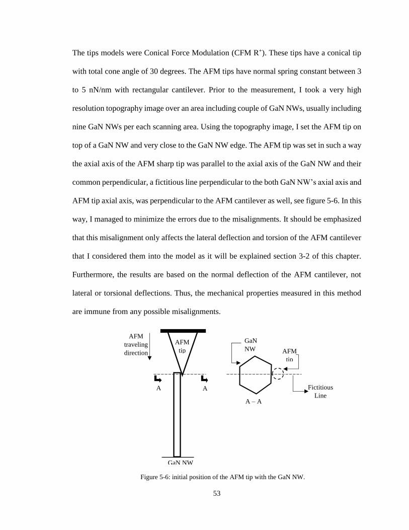
53
The tips models were Conical Force Modulation (CFM R+). These tips have a conical tip
with total cone angle of 30 degrees. The AFM tips have normal spring constant between 3
to 5 nN/nm with rectangular cantilever. Prior to the measurement, I took a very high
resolution topography image over an area including couple of GaN NWs, usually including
nine GaN NWs per each scanning area. Using the topography image, I set the AFM tip on
top of a GaN NW and very close to the GaN NW edge. The AFM tip was set in such a way
the axial axis of the AFM sharp tip was parallel to the axial axis of the GaN NW and their
common perpendicular, a fictitious line perpendicular to the both GaN NW’s axial axis and
AFM tip axial axis, was perpendicular to the AFM cantilever as well, see figure 5-6. In this
way, I managed to minimize the errors due to the misalignments. It should be emphasized
that this misalignment only affects the lateral deflection and torsion of the AFM cantilever
that I considered them into the model as it will be explained section 3-2 of this chapter.
Furthermore, the results are based on the normal deflection of the AFM cantilever, not
lateral or torsional deflections. Thus, the mechanical properties measured in this method
are immune from any possible misalignments.
Figure 5-6: initial position of the AFM tip with the GaN NW.
AFM
tip
A A
A – A
section
GaN
NW AFM
tip
Fictitious
Line
GaN NW
AFM
traveling
direction

54
Lastly, I determined a very small vertical displacement for the AFM tip while it is
recording the normal and lateral displacements of the AFM tip. Before the tip touches the
GaN NW, the normal and lateral displacements of the AFM tip versus the vertical distance
was constant, no increases in the normal and lateral displacements. When the tip meets the
GaN NW, loading cycle, the normal and lateral displacements of the AFM tip increase
almost linearly as the GaN NW is elastically bent from its equilibrium position. During
unloading cycle, the normal and lateral displacements drop suddenly at where the AFM tip
loses its contact with the GaN NW and reaches its ordinary condition, equilibrium
condition. Figure 5-7 shows the acquired plot for loading and unloading cycles.
Figure 5-7: collected data using AFM during loading cycle (red dots) and unloading cycle (blue dots).
I noticed that loading and unloading plots were started and ended at the same point.
This behavior explains that the GaN NWs are acting completely linear elastic for small
deformations [27, 82]. Considering the size of the GaN NW, the thermal vibration of the
GaN NW at room temperature can be ignored [83].
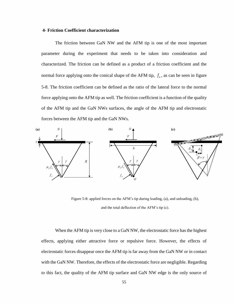
55
4- Friction Coefficient characterization
The friction between GaN NW and the AFM tip is one of the most important
parameter during the experiment that needs to be taken into consideration and
characterized. The friction can be defined as a product of a friction coefficient and the
normal force applying onto the conical shape of the AFM tip, nf , as can be seen in figure
5-8. The friction coefficient can be defined as the ratio of the lateral force to the normal
force applying onto the AFM tip as well. The friction coefficient is a function of the quality
of the AFM tip and the GaN NWs surfaces, the angle of the AFM tip and electrostatic
forces between the AFM tip and the GaN NWs.
Figure 5-8: applied forces on the AFM’s tip during loading, (a), and unloading, (b),
and the total deflection of the AFM’s tip (c).
When the AFM tip is very close to a GaN NW, the electrostatic force has the highest
effects, applying either attractive force or repulsive force. However, the effects of
electrostatic forces disappear once the AFM tip is far away from the GaN NW or in contact
with the GaN NW. Therefore, the effects of the electrostatic force are negligible. Regarding
to this fact, the quality of the AFM tip surface and GaN NW edge is the only source of

56
friction. In order to characterize the effects of the friction, I monitored the normal deflection
of the AFM tip in both loading and unloading cycles. Collecting the normal force in both
loading and unloading results in two sets of data for measuring the values of the friction
and the mechanical properties of the GaN NW. In order to consider the effects of friction
in formula, I wrote the equilibrium equations for the AFM tip during loading and unloading
cycles. It should be emphasized, during the loading and unloading, the both normal and
lateral forces exerting on the GaN NWs have the same directions while only the direction
of the friction between the AFM’s tip and the GaN NWs changes. According to figure 5-
8, writing the equilibrium equations in x and y direction for loading cycle give
0sincos0 fnnx ffFf (1)
0sincos0 nfny ffNf (2)
Dividing the Eq. (1) by Eq. (2) and simplifying the result, it gives
tan
1
tan
tan1
f
f
N
F
(3)
In the above equation, f is the friction coefficient between the AFM’s tip and the GaN
NW which is defined as )tan( f . Utilizing the same procedure for unloading cycle, it
leads to
0sincos0 fnnx ffFf (4)
0sincos0 nfny ffNf (5)
Finally,

57
tan
1
tan
tan1
f
f
N
F
(6)
Substituting the above relationships into the solution of the governing equation, one has a
system of two nonlinear equations that can be solved for and k , for the case of the
MCST, using the Newton-Raphson method.
5- Normal, Lateral and torsional deflections of AFM tip
The vertical distance traveled by the AFM’s tip can be related to the maximum
deflection of the GaN NW and the deflection of the AFM tip as follows
tan0 hw AFM (7)
where AFM is the total deflection of the AFM’s tip which is a summation of the normal,
N , lateral, L , and torsional, T , deflections of the AFM’s tip as
TLNAFM tan . Also h is the distance traveled by the AFM’s tip after
touching the GaN NWs, where the normal force increases as the AFM’s tip moves
downward. In Eq. (7), is the rotation angle of the AFM’s tip, in which RT . The
normal deflection is measured by the AFM gives the normal and lateral forces, Eq. (3) and
Eq. (6). In order to find the lateral stiffness, Lk , and torsional stiffness, Tk , I used the
normal stiffness of the AFM cantilever estimated by AFM and the geometrical dimensions
of the AFM cantilever. The lateral stiffness and the torsional stiffness for a rectangular
cross-section are [84]
N
AFM
AFM
L
L kt
b
L
tbEFk
2
3
3
4
(8)

58
N
AFM
AFM
AFMAFM
AFM
T
T kvR
L
vRL
btETk
13
2
16
23
(9)
where t , b and AFML are the AFM’s cantilever thickness, width and length, respectively.
In addition, the AFMv is the AFM’s Poisson ratio, the AFM’s cantilever was silicon. In Eq.
(9), T is the total torsion applied on the AFM’s tip determined using torsion equilibrium
condition at the point O in figure 5-8. Since the normal and the friction forces intersect at
this point, they do not contribute anything to calculation of the torsion. Moreover, since I
placed the AFM’s tip very close to the GaN NWs edge, the torsion due to nf is negligible
comparing to the torsion due to the lateral force, F . That is why the length of the AFM
tips, R , is several micrometers, for these tips it is m1512 , while the distance between
the point O and nf is in order of nanometer. Therefore, the total exerted torsion on the
AFM’s tip with a good approximation is RFT , which is equivalent to
)tan( RNT .

59
Chapter 6: Results and Discussions
1- Introduction
The experimental results are presented in this chapter. First, I used the MCST
formula to evaluate the mechanical properties of the GaN NWs, the Young’s modulus and
the length scale. Second, I used the MSGT formula to evaluate the mechanical properties
of the GaN NWs as well. Then I compare the results of these theories with the results
obtained using the CCT. Lastly, I explain the inconsistency between the previous literatures
and compare their results with this result.
2- Mechanical properties of GaN NWs based on the MCST
By substituting Eq. (3) from chapter 5 into Eq. (36) from chapter 2 for loading and
Eq. (6) from chapter 5 into Eq. (36) from chapter 2 for unloading, we have two nonlinear
equations that they can be solved using the Newton-Raphson method for the unknown
parameters, the friction coefficient and the rigidity of the GaN NWs. The rigidity of the
GaN NWs is a function of dimensions and the mechanical properties of the GaN NWs.
Interpreting the results for rigidity using the MCST, considering the micro-rotations,
resulted in very uniform values for the Young’s modulus and the length scale of the GaN
NWs. In contrast, the CCT predicts very scatter values for the Young’s modulus. I found
the results are almost insensitive to the small variations of the Poisson ratio, , so that I
considered the Poisson ratio 0.211, as reported by both experimental and theoretical works
[36, 39], to relate the Young’s modulus to the shear modulus through
12
E .

60
In figure 6-1, I fitted the experimental results for the rigidity, considering2AlEI
based on the MCST and IECCT based on the CCT. I added the subscript CCT to the
Young’s modulus to distinguish between the measured values based on the CCT and the
MSCT. The MCST covers all the data points very well for the whole range of radii offering
323 GPa for the Young’s modulus and 13 nm for the length scale. In contrast, the CCT
results significantly depend on the radii. Figures 6-1 and 6-2 show how the CCT
divergences from the experimental data for both small and large radii.
In figure 6-1-a, I fitted the CCT for radii with less than 38 nm, where the Young’s
modulus was estimated to be 409 GPa, while its value is 344 GPa for the radii larger than
65 nm shown in figure 6-1-b. The large difference in the Young’s moduli shows the CCT
is unable to capture the size-dependency of the GaN NWs. Indeed, the CCT results are
highly dependent on the radii since the CCT does not take into account the micro-rotations.
On the other hand, because the MCST considers the micro-rotations with defining
the length scale into the governing equation, it predicts the rigidity of the GaN NWs very
precisely for all range of radii. Equivalently, the CCT is applicable only for short ranges of
aspect ratio and it always overestimates the Young’s modulus due to ignoring the micro-
rotation effects which is a crucial fact in determining size-dependency of the mechanical
properties of the GaN NWs, and all nanostructures.

61
(a)
(b)

62
(c)
Figure 6-1: fitted results of CCT for (a) radius < 38 nm, (b) radius > 65 nm, and (c) 50 nm < radius < 60
nm.
MCST covers all data points very well, error is 0.2%, while CCT cannot cover all data points.
Figure 6-2: Zoomed in on different radii. The experimental data were fitted using the CCT for radii within
50 nm to 65 nm with considering the Young’s modulus of 363 Gpa.

63
3- Mechanical properties of GaN NWs based on the MSGT
By substituting Eq. (3) from chapter 5 into Eq. (44) from chapter 3 for loading and
Eq. (6) from chapter 5 into Eq. (44) from chapter 3 for unloading, we again have two
nonlinear equations that they can be solved using the Newton-Raphson method for the
unknown parameters. Interpreting the experimental data using the MSGT, considering the
higher-order strain gradients, resulted in very uniform values for the Young’s modulus and
the length scale of the GaN NWs. In contrast, the CCT predicts very scatter values for the
Young’s modulus. Here, the Poisson’s ratio assumed to be 0.211 as explained the in section
2.
I firstly used the CCT to predicted the Young’s modulus based on CCT and the
friction between the surfaces. Since the friction only depends on the conditions of surfaces,
I implemented the measured values for friction into the MSGT. Noted the results for the
Young’s modulus based on the CCT are the same as section 2, thus I avoided repeating
CCT’s results here again. For simplicity, I consider all the length scales equal, si ll [65].
Then, I utilized the measured J to predict the length scale as follows
Using J and P , the S and K can be easily determined, which they can be used to estimate
the Young’s modulus of the GaN NWs.
The results for S and 2
slK are plotted in figures 6-3 and 6-4, respectively. The best
fit for the 2
slK gives 132 Gpa as the shear modulus. Considering the Poisson ratio 0.211,
the best fit for S results in 319 Gpa for the Young’s modulus and 8 nm for the length scale.
AJI
IJvls
359315
1225
(8)

64
Figure 6-3: measured S experimentally for each GaN NWs (circles) and MSGT fitting (solid line).
Figure 6-4: 2
slK measured experimentally based on MSGT.
In a professional point of view, no one can compare the MSGT with the CCT or
even the MCST together because the natures of their governing equations are different.

65
The governing equation based on MSGT is a 6th order differential equations while the
governing equation based on the CCT, even the MCST, is a 4th order differential equation.
Regarding to this difference, the concepts of rigidity in these two theories are different.
However, it is possible to define an equivalent Young’s modulus according to the MCST
and the MSGT usable to comparison these three theories with each other. In the next
section, these three theories are compared to each other using the equivalent Young’s
modulus definition.
4- Comparing the results with previous studies
Figure 6-6 shows the equivalent Young’s modulus of the GaN NWs defined based
on the CCT, the MSGT and the MCST. I provided figure 6-6 to illustrate the effects of
micro-rotations and higher strain gradients on the mechanical behaviors of GaN NWs and
the size-dependency of the mechanical properties of GaN NWs. That is why some studies
show that the Young’s modulus of the GaN NWs decreases as the GaN NWs radius
decreases [25, 85], while other studies show that the Young’s modulus increases as the
radius decreases, for example [23, 26-27]. To understand this discrepancy, first I must
define the equivalent Young’s modulus. To do so, I found the relationship of the maximum
deflection of a cantilever GaN NWs, fixed-free boundary condition as shows in figure 6-5,
based on the MCST, the MSGT and the CCT, under a concentrated force,
),,( MSGTMSCTCCTiGi . Then utilizing these relationships, I figured out the
equivalent Young’s modulus, iEqE ( MSGTMSCTCCTi ,, ).

66
MSGTMCSTCCTi
FGw i
,,
0
Figure 6-5: a cantilever GaN NW under a concentrated force at its free end.
After finding iEqE based on each theory, I plugged the Young’s modulus and the
length scale predicted in sections 2 and 3 of this chapter into MCSTEqE and MSGTEqE
relationships, then I plotted them vs. radius in figure 6-6.
In figure 6-6 shows the normalized BulkE , CCTE , MCSTE and MSGTE with respect to
the Young’s modulus of bulk GaN [86], the values of the Young’s modulus for each
individual GaN NWs using the CCT, the MCST and the MSGT, respectively.
Figure 6-6: Experimentally measured Young’s modulus as a function of radius of GaN NWs and then
normalized respect to the Young’s modulus of the bulk GaN. The dots and stars are the experimental
results for each GaN NW. The slid lines are the equivalent Young’s modulus, and the dashed line is the
Young’s modulus of bulk GaN.
F

67
According to figure 6-6, the Young’s moduli predicted by all theories converge to
each other as the radius increases. According to the Cosserats theory [45], as the
dimensions of the nanostructures increases toward the bulk values, the effects of strain
gradients on the rigidity decreases. Indeed, the both theories are the same for bulk
dimensions, and the size-dependency of mechanical properties of materials vanishes at
bulk dimensions. However, reducing the radius of the GaN NWs to less than ~50 nm
significantly increases the size-dependency of the GaN NWs. It should be emphasized that
the results of the MCST and the MSGT are slightly different at small radii. That is why the
MCST only considers only the 2st order strain gradient in its governing equation while the
MSGT considers up to 3rd order strain gradients in its governing equations.
Table 6-1 provides a comprehensive comparison of the Young’s modulus of GaN
NWs estimated with different experimental and theoretical techniques. As it can be seen,
the MCST and the MSGT suggest only a single value for the Young’s modulus of GaN
NWs while the CCT, which used in all earlier literatures and even this results, suggest a
wide domain the Young’s modulus.
Table 6-1: experimental and theoretical on the Young’s modulus of GaN.
Method
Young’s modulus (GPa) Length
Scale (nm) Ref.
Max. Min.
Exper
imen
tall
y
Present Work (MSGT) 319 8 -
Present Work (MCST) 323 13 -
Present Work (CCT) 409 344 - -
Three-point bending 400 194 - [30]
Electromechanical resonator 305 227 - [27]
Nanoindentation 292 298 - [31]

68
Laser Doppler vibrometry 321 201 - [32]
Uniaxial tensile test 250 210 - [23]
Uniaxial compression test 484 223 - [24]
in situ TEM 319 280 - [26]
404 258 - [33]
Theo
reti
call
y First principle 444 - [37]
Electron backscatter diffraction 479 - [38]
Molecular dynamic simulation 290 166 -
[21]
It is worthy to be mentioned, the Young’s modulus of the present GaN NWs based
on the CCT are a little larger than the reported in some literatures, see table 6-1, which can
be attributed to the nature of the experiment. I implemented measurements on the GaN
NWs directly after their fabrication, without any manipulation of the GaN NWs which is
never the case for any other methods. For example, the GaN NWs are cut and transferred
on a trench, for three-point bending [30], or a MEMS device, for tensile test [23], and then
welded on the new substrate. These processes cause partial fracture of GaN NWs and
contaminations, which drastically affect the mechanical properties of GaN NWs [43].
Furthermore, because of the strong bonding between the GaN NWs and the
substrate, GaN-GaN, in the present experiment, there were neither any elastic deformations
nor violation of the boundary conditions at the fixed end of the GaN NWs, which their
existences cause misleading in predicting the mechanical properties of nanostructures [40-
42].

69
Conclusion
In this thesis, the classical, the Young’s modulus and shear modulus, and non-classical,
the length scale parameter, mechanical properties of GaN NWs were measured using the
CCT, the MCST and MSGT. The MCST estimates the Young’s modulus, the shear
modulus and the length scale to be 323 GPa, 133 GPa and 13 nm, respectively. And the
MSGT estimated the Young’s modulus, the shear modulus and the length scale to be 319
GPa, 132 GPa and 8 nm, respectively. Comparing the results of the MCST and the MSGT,
it cannot be easily concluded that the MCST predicts the GaN NWs stiffer than the MSGT
because of slightly higher values of the both classical and non-classical properties of the
GaN NWs. For a precise comparison, the equivalent Young’s modulus should be
considered. That is why the theories governing equations are completely different which
results in different concepts of rigidity and stiffness. Furthermore, the CCT was used to
estimate the Young’s modulus of the GaN NWs. The CCT estimates the Young’s modulus
of the GaN NWs varies from 409 GPa to 344 GPa as the radius increases. Comparing the
results of the MSGT, the MCST and the CCT, the inconsistencies appearing in earlier
publication on mechanical properties of GaN NWs were clearly explained.
Future works
The future works on the GaN-based NWs is going toward smaller and smaller
dimensions which requires a comprehensive development of non-classical properties of
GaN NWs. Consequently, it is crucial to measure the mechanical properties of GaN NWs
in smaller dimensions. In smaller dimensions, the non-classical theories need to be
modified to consider the effects of defects, such as vacancies, interstitial impurities, on

70
covalent bonds in the form of higher strain gradients. Therefore, one of the future work is
to develop a modified non-classical theory including the effects of covalent bonding in its
governing equation and to validate them using experimental measurements.
Moreover, because the GaN NWs are mainly doped in nano-devices, such as LEDs and
piezoelectric devices, it is essential to study the classical and non-classical properties of
GaN NWs with different levels of doping. One way is to dope the GaN template before
starting the fabrication process. It should be emphasized that the level of doping a critical
parameter for preparing the GaN NWs and performance of the GaN NWs.
Furthermore, regarding to the piezoelectric applications of the GaN NWs, it is essential
to study the dynamical behavior of the GaN NWs especially at high frequencies. That is
why the piezoelectric coefficients, which relates the mechanical strains to the electrical
current, are the critical parameters for determining the piezoelectric behavior of the GaN
NWs. Therefore, they must be estimated under precisely demonstrated mechanical
deformations/strains.

71
References
[1]: Nakamura, Shuji, Stephen Pearton, and Gerhard Fasol. The blue laser diode: the complete story. Springer
Science & Business Media, 2013.
[2]: Goldberger, Joshua, et al. "Single-crystal gallium nitride nanotubes." Nature422.6932 (2003): 599-602.
[3]: Westover, Tyler, et al. "Photoluminescence, thermal transport, and breakdown in Joule-heated GaN
nanowires." Nano letters 9.1 (2008): 257-263.
[4]: Hersee, Stephen D., Xinyu Sun, and Xin Wang. "The controlled growth of GaN nanowires." Nano
letters 6.8 (2006): 1808-1811.
[5]: Shul, RJa, et al. "Comparison of plasma etch techniques for III–V nitrides."Solid-State Electronics 42.12
(1998): 2259-2267.
[6]: Beach, R. A., and T. C. McGill. "Piezoelectric fields in nitride devices."Journal of Vacuum Science &
Technology B 17.4 (1999): 1753-1756.
[7]: Minary-Jolandan, Majid, et al. "Individual GaN nanowires exhibit strong piezoelectricity in 3D." Nano
letters 12.2 (2012): 970-976.
[8]: Weber, J. C., et al. "Gallium nitride nanowire probe for near-field scanning microwave
microscopy." Applied Physics Letters 104.2 (2014): 023113.
[9]: Bao, Wei, et al. "Carrier Localization Effects in InGaN/GaN Multiple-Quantum-Wells LED Nanowires:
Luminescence Quantum Efficiency Improvement and “Negative” Thermal Activation Energy." Scientific
Reports6 (2016).
[10]: Duan, Xiangfeng, and Charles M. Lieber. "Laser-assisted catalytic growth of single crystal GaN
nanowires." Journal of the American Chemical Society122.1 (2000): 188-189.
[11]: Liu, Baodan, et al. "Wurtzite-type faceted single-crystalline GaN nanotubes."Applied physics
letters 88.9 (2006): 93120-93120.
[12]: Ishida, Akihiro, et al. "Design and preparation of AlN/GaN quantum wells for quantum cascade laser
applications." Japanese journal of applied physics44.8R (2005): 5918.
[13]: Winkler, Holger, et al. "Quantum‐Confined Gallium Nitride in MCM‐41."Advanced materials 11.17
(1999): 1444-1448.
[14]: Dayeh, Shadi A., Anna Fontcuberta i Morral, and Chennupati Jagadish. Semiconductor Nanowires II:
Properties and Applications. Vol. 94. Academic Press, 2016.
[15]: Rieger, W., et al. "Influence of substrate‐induced biaxial compressive stress on the optical properties of
thin GaN films." Applied physics letters 68.7 (1996): 970-972.
[16]: Kim, Kwiseon, Walter RL Lambrecht, and Benjamin Segall. "Electronic structure of GaN with strain
and phonon distortions." Physical Review B 50.3 (1994): 1502.
[17]: Signorello, G., et al. "Inducing a direct-to-pseudodirect bandgap transition in wurtzite GaAs nanowires
with uniaxial stress." Nature communications 5 (2014).
[18]: Wen, Yu-Hua, Zi-Zhong Zhu, and Ru-Zeng Zhu. "Molecular dynamics study of the mechanical
behavior of nickel nanowire: Strain rate effects." Computational Materials Science 41.4 (2008): 553-560.
[19]: Wang, Zhiguo, et al. "Atomistic simulation of brittle to ductile transition in GaN nanotubes." Applied
physics letters 89.24 (2006): 243123.
[20]: Le, Minh-Quy. "Atomistic study on the tensile properties of hexagonal AlN, BN, GaN, InN and SiC
sheets." Journal of Computational and Theoretical Nanoscience 11.6 (2014): 1458-1464.
[21]: Wang, Zhiguo, et al. "Mechanical behavior of gallium nitride nanotubes under combined tension-
torsion: An atomistic simulation." Journal of Applied Physics 103.1 (2008): 013505.
[22]: Wang, Guofeng, and Xiaodong Li. "Predicting Young’s modulus of nanowires from first-principles
calculations on their surface and bulk materials." Journal of Applied Physics 104.11 (2008): 113517.
72
[23]: Brown, J. J., et al. "Tensile measurement of single crystal gallium nitride nanowires on MEMS test
stages." Sensors and Actuators A: Physical 166.2 (2011): 177-186.
[24]: Wang, Zhiguo, et al. "Buckling of GaN nanotubes under uniaxial compression." Solid State
Communications 146.7 (2008): 293-297.
[25]: Nam, Chang-Yong, et al. "Diameter-dependent electromechanical properties of GaN nanowires." Nano
letters 6.2 (2006): 153-158.
[26]: Bernal, Rodrigo A., et al. "Effect of growth orientation and diameter on the elasticity of GaN nanowires.
A combined in situ TEM and atomistic modeling investigation." Nano letters 11.2 (2010): 548-555.
[27]: Huang, Jian Yu, et al. "In situ nanomechanics of GaN nanowires." Nano letters 11.4 (2011): 1618-1622.
[28]: Espinosa, Horacio D., Rodrigo A. Bernal, and Tobin Filleter. "In situ TEM electromechanical testing
of nanowires and nanotubes." Small 8.21 (2012): 3233-3252.
[29]: Ni, Hai, et al. "Elastic modulus of single-crystal GaN nanowires." Journal of materials research 21.11
(2006): 2882-2887.
[30]: Chen, Yunxia, et al. "Mechanical elasticity of vapour–liquid–solid grown GaN
nanowires." Nanotechnology 18.13 (2007): 135708.
[31]: Feng, Gang, et al. "A study of the mechanical properties of nanowires using nanoindentation." Journal
of Applied Physics 99.7 (2006): 074304.
[32]: Ben Amar, Achraf, et al. "Young's modulus extraction of epitaxial heterostructure AlGaN/GaN for
MEMS application." physica status solidi (a)211.7 (2014): 1655-1659.
[33]: Dai, Sheng, et al. "Elastic properties of GaN nanowires: Revealing the influence of planar defects on
Young’s modulus at nanoscale." Nano letters15.1 (2014): 8-15.
[34]: Moram, M. A., Z. H. Barber, and C. J. Humphreys. "Accurate experimental determination of the
Poisson’s ratio of GaN using high-resolution x-ray diffraction." Journal of applied physics 102.2 (2007):
023505.
[35]: Polian, A., M. Grimsditch, and I. Grzegory. "Elastic constants of gallium nitride." Journal of Applied
Physics 79.6 (1996): 3343-3344.
[36]: Davydov, V. Yu, et al. "Raman and photoluminescence studies of biaxial strain in GaN epitaxial layers
grown on 6H–SiC." Journal of applied physics82.10 (1997): 5097-5102.
[37]: Hoang, M. T., et al. "Size-dependent mechanical properties of axial and radial mixed AlN/GaN
nanostructure." Nanotechnology 26.11 (2015): 115703.
[38]: Shao, Yongliang, et al. "Large Area Stress Distribution in Crystalline Materials Calculated from Lattice
Deformation Identified by Electron Backscatter Diffraction." Scientific reports 4 (2014).
[39]: Shimada, Kazuhiro, Takayuki Sota, and Katsuo Suzuki. "First-principles study on electronic and elastic
properties of BN, AlN, and GaN." Journal of Applied Physics 84.9 (1998): 4951-4958.
[40]: Zhang, Yin, and Ya-Pu Zhao. "Adhesive contact of nanowire in three-point bending test." Journal of
Adhesion Science and Technology 25.10 (2011): 1107-1129.
[41]: Gangadean, D., et al. "Winkler boundary conditions for three-point bending tests on 1D
nanomaterials." Nanotechnology 21.22 (2010): 225704.
[42]: Keer, L. M., John Dundurs, and K. C. Tsai. "Problems involving a receding contact between a layer and
a half space." Journal of Applied Mechanics39.4 (1972): 1115-1120.
[43]: Song, Jinhui, et al. "Elastic property of vertically aligned nanowires." Nano Letters 5.10 (2005): 1954-
1958.
[44]: Yang, J. F. C., and Roderic S. Lakes. "Experimental study of micropolar and couple stress elasticity in
compact bone in bending." Journal of biomechanics 15.2 (1982): 91-98.
[45]: Cosserat, E., and F. Cosserat. "Deformable Bodies." Scientific Library A. Hermann and Sons (1909).
[46]: Asghari, M., et al. "The modified couple stress functionally graded Timoshenko beam
formulation." Materials & Design 32.3 (2011): 1435-1443.

73
[47]: Ma, H. M., X-L. Gao, and J. N. Reddy. "A microstructure-dependent Timoshenko beam model based
on a modified couple stress theory." Journal of the Mechanics and Physics of Solids 56.12 (2008): 3379-
3391.
[48]: Park, S. K., and X. L. Gao. "Bernoulli–Euler beam model based on a modified couple stress
theory." Journal of Micromechanics and Microengineering 16.11 (2006): 2355.
[49]: Qi, H. J., et al. "Determination of mechanical properties of carbon nanotubes and vertically aligned
carbon nanotube forests using nanoindentation."Journal of the Mechanics and Physics of Solids 51.11
(2003): 2213-2237.
[50]: Poncharal, Philippe, et al. "Electrostatic deflections and electromechanical resonances of carbon
nanotubes." science 283.5407 (1999): 1513-1516.
[51]: Gao, Zhiyuan, et al. "Dynamic fatigue studies of ZnO nanowires by in‐situ transmission electron
microscopy." physica status solidi (RRL)-Rapid Research Letters 3.7‐8 (2009): 260-262.
[52]: Ryu, Seung Yoon, et al. "Lateral buckling mechanics in silicon nanowires on elastomeric
substrates." Nano letters 9.9 (2009): 3214-3219.
[53]: Zhu, Yong. "In Situ Nanomechanical Testing of Crystalline Nanowires in Electron
Microscopes." JOM 68.1 (2016): 84-93.
[54]: Feng, Gang, et al. "A study of the mechanical properties of nanowires using nanoindentation." Journal
of Applied Physics 99.7 (2006): 074304.
[55]: Truesdell, Clifford, ed. Linear Theories of Elasticity and Thermoelasticity: Linear and Nonlinear
Theories of Rods, Plates, and Shells. Vol. 2. Springer, 2013.
[56]: Hadjesfandiari, Ali R., and Gary F. Dargush. "Evolution of generalized couple-stress continuum
theories: a critical analysis." arXiv preprint arXiv:1501.03112 (2014).
[57]: Mindlin, R. D., and H. F. Tiersten. "Effects of couple-stresses in linear elasticity." Archive for Rational
Mechanics and analysis 11.1 (1962): 415-448.
[58]: KOlTER, W. T. "Couple stresses in the theory of elasticity." Proc. Koninklijke Nederl. Akaad. van
Wetensch 67 (1964).
[59]: Yang, F. A. C. M., et al. "Couple stress based strain gradient theory for elasticity." International Journal
of Solids and Structures 39.10 (2002): 2731-2743.
[60]: Abadi, M. Mohammad, and A. R. Daneshmehr. "An investigation of modified couple stress theory in
buckling analysis of micro composite laminated Euler–Bernoulli and Timoshenko beams." International
Journal of Engineering Science 75 (2014): 40-53.
[61]: Tsiatas, George C., and Aristophanes J. Yiotis. "A modified couple stress theory for bending, buckling
and vibration of skew orthotropic micro-plates." Proc. 10th HSTAM Int. Congress of Mechanics, Chania.
2013.
[62]: Mindlin, R. D., and N. N. Eshel. "On first strain-gradient theories in linear elasticity." International
Journal of Solids and Structures 4.1 (1968): 109-124.
[63]: Fleck, N. A., and J. W. Hutchinson. "A phenomenological theory for strain gradient effects in
plasticity." Journal of the Mechanics and Physics of Solids 41.12 (1993): 1825-1857.
[64]: Fleck, N. A., and J. W. Hutchinson. "A reformulation of strain gradient plasticity." Journal of the
Mechanics and Physics of Solids 49.10 (2001): 2245-2271.
[65]: Lam, David CC, et al. "Experiments and theory in strain gradient elasticity." Journal of the Mechanics
and Physics of Solids 51.8 (2003): 1477-1508.
[66]: Kahrobaiyan, M. H., et al. "A nonlinear strain gradient beam formulation." International Journal of
Engineering Science 49.11 (2011): 1256-1267.
[67]: Akgöz, B., and Ö. Civalek. "Buckling analysis of cantilever carbon nanotubes using the strain gradient
elasticity and modified couple stress theories." Journal of Computational and Theoretical Nanoscience 8.9
(2011): 1821-1827.
[68]: Kong, Shengli, et al. "Static and dynamic analysis of micro beams based on strain gradient elasticity
theory." International Journal of Engineering Science 47.4 (2009): 487-498.

74
[69]: Akgöz, Bekir, and Ömer Civalek. "Analysis of micro-sized beams for various boundary conditions
based on the strain gradient elasticity theory." Archive of Applied Mechanics 82.3 (2012): 423-443.
[70]: DiVincenzo, D. P. "Dispersive corrections to continuum elastic theory in cubic crystals." Physical
Review B 34.8 (1986): 5450.
[71]: Maranganti, R., and P. Sharma. "A novel atomistic approach to determine strain-gradient elasticity
constants: Tabulation and comparison for various metals, semiconductors, silica, polymers and the (ir)
relevance for nanotechnologies." Journal of the Mechanics and Physics of Solids 55.9 (2007): 1823-1852.
[72]: Askes, Harm, and Elias C. Aifantis. "Gradient elasticity in statics and dynamics: an overview of
formulations, length scale identification procedures, finite element implementations and new
results." International Journal of Solids and Structures 48.13 (2011): 1962-1990.
[73]: Giannozzi, Paolo, et al. "Ab initio calculation of phonon dispersions in semiconductors." Physical
Review B 43.9 (1991): 7231.
[74]: Soler, José M., et al. "The SIESTA method for ab initio order-N materials simulation." Journal of
Physics: Condensed Matter 14.11 (2002): 2745.
[75]: Maradudin, Alexei A. "Theory of lattice dynamics in the harmonic approximation." (1971).
[76]: Kunc, K., and O. Holm Nielsen. "Lattice dynamics of zincblende structure compounds using
deformation-dipole model and rigid ion model." Computer Physics Communications 16.2 (1979): 181-197.
[77]: Behzadirad, Mahmoud, et al. "GaN nanowire tips for nanoscale atomic force
microscopy." Nanotechnology 28.20 (2017): 20LT01.
[78]: Brueck, S. R. J. "Optical and interferometric lithography-nanotechnology enablers." Proceedings of the
IEEE 93.10 (2005): 1704-1721.
[79]: Hersee, Stephen D., Xinyu Sun, and Xin Wang. "The controlled growth of GaN nanowires." Nano
letters 6.8 (2006): 1808-1811.
[80]: Chen, Weijie, et al. "GaN nanowire fabricated by selective wet-etching of GaN micro truncated-
pyramid." Journal of Crystal Growth 426 (2015): 168-172.
[81]: Li, Qiming, et al. "Optical performance of top-down fabricated InGaN/GaN nanorod light emitting
diode arrays." Optics express 19.25 (2011): 25528-25534.
[82]: Wang, Zhiguo, et al. "Orientation and temperature dependence of the tensile behavior of GaN
nanowires: an atomistic study." Journal of Materials Science: Materials in Electronics 19.8-9 (2008): 863-
867.
[83]: Treacy, MM JEBBESSEN, T. W. Ebbesen, and J. M. Gibson. "Exceptionally high Young's modulus
observed for individual carbon nanotubes." Nature 381.6584 (1996): 678.
[84]: Sadd, Martin H. Elasticity: theory, applications, and numerics. Academic Press, 2009.
[85]: Gulans, Andris, and Ivars Tale. "Ab initio calculation of wurtzite‐type GaN nanowires." physica status
solidi (c) 4.3 (2007): 1197-1200.
[86]: Fujikane, Masaki, et al. "Elastic–plastic transition during nanoindentation in bulk GaN crystal." Journal
of Alloys and Compounds 450.1 (2008): 405-411.