investigating granular milling in a hammer mill: … investigating granular milling in a hammer...
TRANSCRIPT
1
Investigating granular milling in a hammer mill: experiments and simulation
S. Naik and B. Chaudhuri Department of Pharmaceutical Sciences, University of Connecticut, USA
Abstract
Particle size reduction of dry material by milling is a key unit operation for the pharmaceutical, agricultural, food and paper industries. Knowledge of particle flow and size reduction in a hammer mill is thus critical to optimize the design and operation of such equipment. Milling experiments are performed using lactose non pareils in a laboratory scale Hammer Mill. The size and shape of the resultant progeny of particles are analyzed by sieves/light scattering and microscope/image analysis techniques respectively. Discrete Element Method (DEM) based computational methods are developed to perform a quantitative examination of granular flow, fracturing and subsequently fragmentation patterns for the same hammer mill. A parametric study was performed to understand the effect of hammer speed (rotational), feed rate, hammer-wall tolerance on size reduction process. Simulations were carried out to study the effect of mill speed on kinetic energy of particles. Keywords: discrete element method, granular flow, fragmentation, hammer mill.
1 Introduction
Particle size reduction of dry granular material by mechanical means, also known as milling or communition, is undoubtedly a very important unit operation in pharmaceutical, agricultural, food, mineral and paper industries. For example, particle size reduction has a significant impact on pharmaceutical product performance and stability as it affects the solubility and bioavailability of many poorly soluble BCS Class II drugs [1]. The most commonly used mills are the rotary cutter, hammer mill, roller mill, ball mills and fluid energy mills, used in various stages of manufacturing. Size reduction is generally achieved by particle
Computational Methods and Experimental Measurements XV 121
www.witpress.com, ISSN 1743-355X (on-line) WIT Transactions on Modelling and Simulation, Vol 51, © 2011 WIT Press
doi:10.2495/CMEM110121

2
fracturing and subsequent fragmentation under the action of externally applied energy Surface characteristic and fracture pattern under an applied energy is not only influenced by material properties but also by operational conditions of mill. Knowledge of particle flow, granular fracturing and size reduction in a mill is thus very critical to optimize and to scale up this operation. Substantial effort has been expended in last three decades to understand the milling performance as a function of material properties, operational conditions and machine configuration. Several experimental and mathematical approaches to understand the milling behavior in Ball Mill have been performed [2–6]. Experiments and Discrete Element Method (DEM) based modeling of milling of pharmaceutical excipients in a very small scale oscillatory single was performed by Kwan et al. [7]. Campbell et al. [8] developed the relationship between the inlet and outlet particle size distribution in a roller milling operation. The impact mills have been investigated by Austin [9], Gotsis and Austin [10], Vogel and Peukert [11] and Djordjevic et al. [12] for different materials. Austin developed simplified analytical model of high speed milling of limestone, cement in hammer mill with parameters chosen to match the model prediction to the experimental findings, whereas PMMA/Glass and rock was the material of interest for Vogel and Djordjevic. A comprehensive understanding of the fragmentation mechanism from experiments helped the development of a series of mechanistic and population balance based models [13–15]. However, these models completely ignore the inter-particle and particle boundary interaction which dictates granular flow behavior. DEM explicitly considers inter-particle and particle wall interactions, providing an effective tool to simulate particles kinematics and granular fragmentation. Comprehensive modeling of milling based on first principles was attempted by Djordjevic et al. [12] using discrete element method (DEM), where granular flow properties are considered. This DEM based direct modeling of the milling process is limited to a small number (a few hundred) of spherical particles, and derived essentially no conclusions regarding optimization, control or scale-up of milling performance. To the best of our knowledge, no previous work has used 3D DEM to study granular milling of pharmaceutical granules in hammer mill. In this article, experiment and 3D DEM modeling based method, to better understand milling behavior of pharmaceutical powders in hammer mill is presented. The effect of material properties and operational conditions on milling performance is also determined.
2 Experimental
The milling equipment (Thomas Wiley Mill, Thomas Scientific, Swedesboro, NJ) used in our study is a variable speed, digitally controlled, direct drive mill; that provides continuous variation of cutting speeds from 650 to 1140 rpm with constant torque maintained throughout the speed range. Once the material is loaded through the feed hopper in to the grinding chamber, it drops by gravity and fragments after colliding with the rotating hammers. Parametric studies are conducted to study the effect of speed, load, and impeller wall distance and feed rate on particle size reduction. The experiments were performed using lactose
122 Computational Methods and Experimental Measurements XV
www.witpress.com, ISSN 1743-355X (on-line) WIT Transactions on Modelling and Simulation, Vol 51, © 2011 WIT Press

3
non pareils. In our milling experiments the material is fed at the top center, thrown out centrifugally at first impact with the hammers and ground by impact against the wall or cut due to presence of hammers at the periphery. The material is retained until it is small enough to fall through the screen that forms the lower portion of the casing. Particles fine enough to pass through the screen is discharged almost as fast as they are formed in a glass container. To obtain rigorous information for the parametric studies, samples are collected in the glass container at regular intervals for example, 5 seconds for the first four samples, 10 seconds for the next four samples and 20 seconds for the next samples. All experiments are conducted at least thrice at room temperature of 28C and relative humidity of 35% to ensure repeatability. The effect of experimental factor was studied at two-three levels. Average particle sizes for the entire sample are calculated from sieve analysis using Rotap Sieve analyzer determination was done by sieve analysis. Particle shape analysis was performed by Optical Microscope-Camera (Olympus SZ61) and Image Analysis software (Image Pro Plus). The conditions examined using the Wiley Mill are enlisted in Table 1.
Table 1: Conditions examined for the milling experiments with lactose.
Parameters
Speed 600rpm - 1140rpm
Clearance 2.9mm-3.7mm
Feed rate 60g/min-100g/min
3 Computational method
Numerical simulations were performed using the Discrete Element Method (DEM) originally developed by Cundall and Strack [13, 14]. In this model the granular material is considered as a collection of frictional inelastic spherical particles. Each particle interacts with its neighbors or with the boundary only at contact points through normal and tangential forces. The forces and torques acting on each of the particles are calculated in the following way:
Fi = mig + FN + FT +Fcohes (1)
Ti = ri FT (2) The force on each particle is given by the sum of gravitational, inter-particle (normal and tangential FN and FT) and cohesive forces (Fcohes ) as indicated in eq. (1) and eq (2). The corresponding torque on each particle is the sum of the moment of the tangential forces (FT) arising from inter-particle contacts (eq. (2)). The normal forces (FN ) and the tangential forces (FT) in inter-particle or particle-wall collision were calculated with the “latching spring model” and “incrementally slipping model” respectively, developed by Walton [15].
Computational Methods and Experimental Measurements XV 123
www.witpress.com, ISSN 1743-355X (on-line) WIT Transactions on Modelling and Simulation, Vol 51, © 2011 WIT Press
4
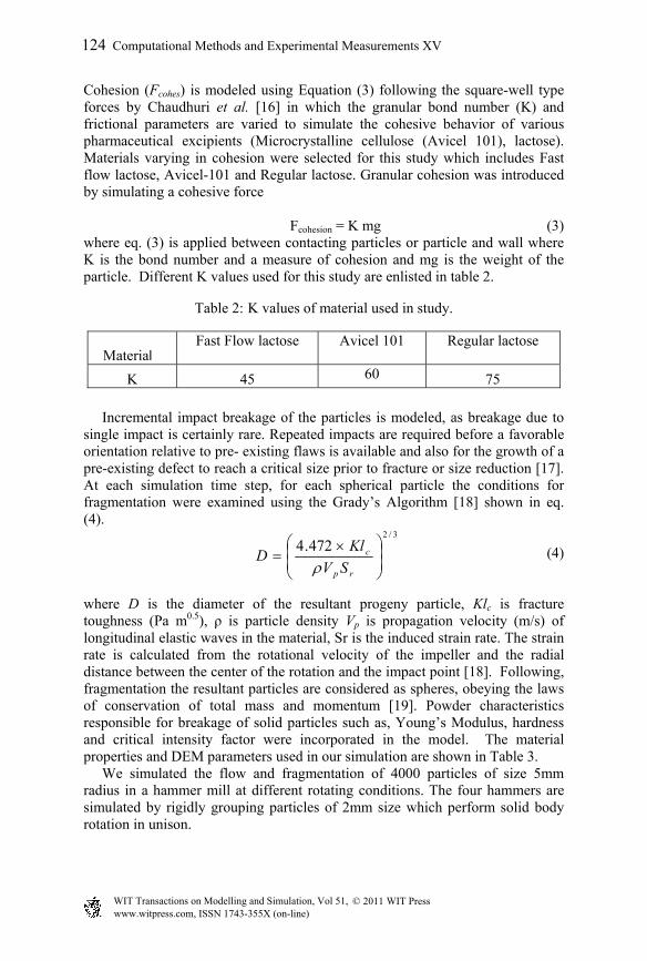
Cohesion (Fcohes) is modeled using Equation (3) following the square-well type forces by Chaudhuri et al. [16] in which the granular bond number (K) and frictional parameters are varied to simulate the cohesive behavior of various pharmaceutical excipients (Microcrystalline cellulose (Avicel 101), lactose). Materials varying in cohesion were selected for this study which includes Fast flow lactose, Avicel-101 and Regular lactose. Granular cohesion was introduced by simulating a cohesive force
Fcohesion = K mg (3) where eq. (3) is applied between contacting particles or particle and wall where K is the bond number and a measure of cohesion and mg is the weight of the particle. Different K values used for this study are enlisted in table 2.
Table 2: K values of material used in study.
Material Fast Flow lactose Avicel 101 Regular lactose
K 45 60 75 Incremental impact breakage of the particles is modeled, as breakage due to single impact is certainly rare. Repeated impacts are required before a favorable orientation relative to pre- existing flaws is available and also for the growth of a pre-existing defect to reach a critical size prior to fracture or size reduction [17]. At each simulation time step, for each spherical particle the conditions for fragmentation were examined using the Grady’s Algorithm [18] shown in eq. (4).
(4) where D is the diameter of the resultant progeny particle, Klc is fracture toughness (Pa m0.5), ρ is particle density Vp is propagation velocity (m/s) of longitudinal elastic waves in the material, Sr is the induced strain rate. The strain rate is calculated from the rotational velocity of the impeller and the radial distance between the center of the rotation and the impact point [18]. Following, fragmentation the resultant particles are considered as spheres, obeying the laws of conservation of total mass and momentum [19]. Powder characteristics responsible for breakage of solid particles such as, Young’s Modulus, hardness and critical intensity factor were incorporated in the model. The material properties and DEM parameters used in our simulation are shown in Table 3. We simulated the flow and fragmentation of 4000 particles of size 5mm radius in a hammer mill at different rotating conditions. The four hammers are simulated by rigidly grouping particles of 2mm size which perform solid body rotation in unison.
3/2
472.4
rp
c
SV
KlD
124 Computational Methods and Experimental Measurements XV
www.witpress.com, ISSN 1743-355X (on-line) WIT Transactions on Modelling and Simulation, Vol 51, © 2011 WIT Press

5
Table 3: DEM parameters for simulation.
4 Results and discussion
4.1 Experiments
4.1.1 Effect of feed rate It is important to study the effect of feed rate on size reduction since it determines the hold up of material in sizing chamber and hence energy required for size reduction. Milling experiments are performed at two different feed rates of 60g/min and 100g/min while the hammers are rotated at 600rpm and 1140 rpm. The hammer-wall clearance is kept constant at 2.9mm. Mean particle size for all samples at different time intervals were measured. As depicted in Figure 1a and Figure 1b a lower feed rate produced a smaller size distribution at the given impeller speeds. Besides achieving a smaller particle size, the feed rate at 60g/sec reduced the polydispersity of the sample at 1140 rpm, producing almost a constant particle size of around 450um. Thus the right choice of the feed rate and mill speed can also enable us to produce not only a small size but also control the variability in size distribution. A lower size distribution is obtained at lower feed rate due to longer path lengths of particles resulting in higher impact velocity and hence a finer size distribution. At higher hold up the number of collisions is high, but the kinetic energy per particle may be low leading to poor breakage probability.
DEM parameters Values
Total number of particles 4000
Radius of the particles 5mm
Hopper angle 72.83 degrees
Coefficient of restitution
Particle/particle 0.7
Particle/wall 0.5
Normal stiffness coefficient
Particle/particle 600N/m
Particle/wall 600N/m
Friction coefficient particle/particle 0.7
Friction coefficient particle/wall 0.3 Time step 2.0 * 10-5 seconds Young Modulus 22.13 – 9.8 GPa
Critical Stress Intensity 0.5 – 0.8 MPa m0.5
Computational Methods and Experimental Measurements XV 125
www.witpress.com, ISSN 1743-355X (on-line) WIT Transactions on Modelling and Simulation, Vol 51, © 2011 WIT Press

6
(a)
(b)
Figure 1: (a) Effect of feed rate on particle size reduction at hammer tip speed of 600rpm. (b) Effect of feed rate on particle size reductions at hammer tip speed of 1140rpm.
4.1.2 Effect of speed The speed of the impeller determines the mechanism of size reduction. In most cases lower speeds result in attrition whereas as higher speeds cause size reduction by impact. Figure 2 depicts the behavior of size reduction upon changing the speed at a given feed rate. A higher speed of the mill produced smaller particle size. A high feed rate with lower speed can result in choking of the mill and can slow the process to a great extent. This is because under such conditions the power consumption of the motor increases and rotation speed decreases. 4.1.2.1 Shape analysis Particle shape analysis was performed using Optical Microscope-Camera (Olympus SZ61) and Image Analysis software (Image Pro Plus). Analysis of samples at an impeller speed of 600rpm, feed rate of 60g/min and a clearance of 2.9mm revealed a mechanism of chipping and attrition as shown in Figure 3a. For samples at a speed of 1140 rpm as shown in Figure 3b, the particle shape revealed that most probably, size reduction by fragmentation dominates. This s because of the greater centrifugal force experienced by the particle at higher impeller speeds.
0
200
400
600
800
0 80 160 240 320 400
Ave
rage
par
ticl
e si
ze(m
icro
ns)
Time in seconds
100g/min
60g/min
0
100
200
300
400
500
600
700
800
900
0 200 400
Average
particle size(m
icrons)
Time in seconds
100g/min
60g/min
126 Computational Methods and Experimental Measurements XV
www.witpress.com, ISSN 1743-355X (on-line) WIT Transactions on Modelling and Simulation, Vol 51, © 2011 WIT Press

7
Figure 2: Change of average particle size with time as a function of Impeller speed.
Figure 3: (a) Shape analysis of particles at clearance of 2.9mm, 600rpm. (b) Shape analysis of particles at clearance of 2.9mm, 1140rpm.
4.1.3 Effect of clearance on size reduction The distance between the hammer and the wall is an important factor that controls size reduction. A larger clearance can result in continuous rolling of particles and hence significantly reduce the rate of size reduction. A very small tolerance on the other hand increases fine formation resulting in increased energy consumption by the mill. The hammer wall clearance is determined by the intrusion of four knives from the inner wall of mill. The knives are situated at 1.5” a part of the circular inner wall of mill. Figure 4a and Figure 4b depict the behavior of size reduction upon changing the clearance at a given feed rate and speed. This change in clearance significantly influenced the mechanism of size reduction, changing it from impact to a combination of rolling and attrition
0
100
200
300
400
500
600
700
800
900
0 200 400
Average
particle size
(microns)
Time in seconds
100g/min,650rpm
100g/min,870rpm
100g/min,1140rpm
(a) (b)
Computational Methods and Experimental Measurements XV 127
www.witpress.com, ISSN 1743-355X (on-line) WIT Transactions on Modelling and Simulation, Vol 51, © 2011 WIT Press

8
irrespective of hammer speeds. This is because much of the particle shape was retained at hammer tolerance of 3.7mm whereas fragmentation was observed at hammer wall tolerance of 2.9mm As seen in figure 4a and figure 4b increasing the clearance decreased the rate of size reduction of the mill. This resulted in accumulation of particles in chamber. As a consequence, the particle size distribution turned coarser and wider.
(a)
(b)
Figure 4: (a) Change of average particle size with time as a function of clearance at 600rpm. (b) Change of average particle size with time as a function of clearance at 1140rpm.
4.2 Numerical simulations of granular flow and fragmentation
4.2.1 Effect of speed The flow and fragmentation of particles in the hammer mill is simulated using DEM as described in section 3. The hammer mill geometry is similar to the one used in our experiments and is implemented in the particle dynamics simulation. We use 4000 spherical particles with material properties described in table 1. Initially all particles are deposited in the hopper. The hopper outlet is chosen to be closed during the deposition of particles. After deposition particles are discharged from hopper into the hammer mill. The hammer is also set into motion at prescribed velocity of 650–1140 rpm. The DEM predicted velocity data is used to calculate the temporal function of total kinetic energy of the particles at different impeller speeds as illustrated in Figure 5.
0100200300400500600700800900
0 200 400
Averge particle Size(m
icrons)
Time in seconds
3.7mm
2.9mm
0
100
200
300
400
500
600
700
800
900
0 200 400 600
Averge Particle Size(m
icrons)
Time in seconds
3.7mm
2.9mm
128 Computational Methods and Experimental Measurements XV
www.witpress.com, ISSN 1743-355X (on-line) WIT Transactions on Modelling and Simulation, Vol 51, © 2011 WIT Press

9
Figure 5: Temporal variation of kinetic energy of particles as function of speed.
The increase in kinetic energy of particles with increase in impeller speed is due to greater centrifugal forces, is well predicted by the simulation model. The velocity vector profiles of all particles illustrated in figure 6a and 6b further corroborates the greater impact experienced by the particle at higher speed of 1140rpm as compared to lower speed of 650 rpm.
Figure 6: (a) Velocity profile of particles at 650 rpm. (b) Velocity profile of particles at 650 rpm.
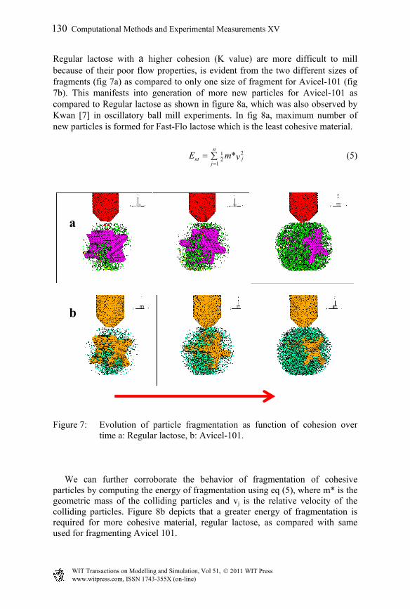
4.2.2 Effect of material properties The effect of granular cohesion on fragmentation is examined while keeping the operational condition (650rpm, 2.9mm clearance) constant. As described in section 3, the materials of different levels of cohesion is simulated by varying K value were used. Figures 7a and 7b shows the time series of axial snapshots from simulation of fragmentation of Avicel-101 (MCC) and Regular Lactose granules.
0.00E+00
1.00E+01
2.00E+01
3.00E+01
4.00E+01
5.00E+01
6.00E+01
7.00E+01
0 1 2 3
Kinetic energy(Nm)
Time in seconds
650rpm
870rpm
1140rpm
(a) (b)
-0.25 -0.2 -0.15 -0.1 -0.05 0 0.05 0.1 0.15 0.2 0.25-0.25
-0.2
-0.15
-0.1
-0.05
0
0.05
0.1
0.15
0.2
0.25
650 [email protected] -0.2 -0.15 -0.1 -0.05 0 0.05 0. 0.15 0.2 0.25
-0.25
-0.2
-0.15
-0.1
-0.05
0
0.05
0.1
0.15
0.2
0.25
Computational Methods and Experimental Measurements XV 129
www.witpress.com, ISSN 1743-355X (on-line) WIT Transactions on Modelling and Simulation, Vol 51, © 2011 WIT Press
10
Regular lactose with a higher cohesion (K value) are more difficult to mill because of their poor flow properties, is evident from the two different sizes of fragments (fig 7a) as compared to only one size of fragment for Avicel-101 (fig 7b). This manifests into generation of more new particles for Avicel-101 as compared to Regular lactose as shown in figure 8a, which was also observed by Kwan [7] in oscillatory ball mill experiments. In fig 8a, maximum number of new particles is formed for Fast-Flo lactose which is the least cohesive material.
212
1*
n
jntj
E m v
(5)
Figure 7: Evolution of particle fragmentation as function of cohesion over time a: Regular lactose, b: Avicel-101.
We can further corroborate the behavior of fragmentation of cohesive particles by computing the energy of fragmentation using eq (5), where m* is the geometric mass of the colliding particles and vj is the relative velocity of the colliding particles. Figure 8b depicts that a greater energy of fragmentation is required for more cohesive material, regular lactose, as compared with same used for fragmenting Avicel 101.
a
b
130 Computational Methods and Experimental Measurements XV
www.witpress.com, ISSN 1743-355X (on-line) WIT Transactions on Modelling and Simulation, Vol 51, © 2011 WIT Press

11
(a) (b)
Figure 8: (b) Effect of cohesion on fragmentation of particles. (b) Effect of cohesion on fragmentation energy.
5 Conclusion
DEM simulation and experiment based parametric studies is performed to study the effect of different operating conditions on size reduction in a hammer mill. In experiments, greater size reduction is observed at higher speeds and low feed rates owing to the greater centrifugal force experienced by the particles and longer mean free path lengths respectively. Particle shape analysis reveals fragmentation as the dominant process of size reduction in Hammer mill under the investigated conditions. In simulation, we find the kinetic energy of particles increases with impeller speed contributing greater fragmentation. Materials with higher cohesion show lower fragmentation.
References
[1] Jounela A.J., Pentikainen P.J., Sothmann A., Effect of particle size on the bioavailability of digoxin. European Journal of Clinical Pharmacology 8, pp. 365-370, 1975.
[2] Clearly P.W., Predicting charge motion, power draw, segregation, wear and particle breakage in ball mills using discrete element method, Miner. Eng., 11, pp. 1061-1080, 1998.
[3] Watanbe, H., Critical rotation speed for ball-milling, Powder Technology, 104, pp. 95-99, 1999.
[4] Misra B.K., Rajamani R.K., Simulation of charge motion in ball mills, Part 2: numerical simulations, Int. J. Miner. Processing, 40, pp. 187-197,1994.
0
4000
8000
12000
16000
0 0.5 1 1.5 2 2.5 3
New
part
icle
s
Time (s)
Fast-Flo Lactose
Avicel 101
Regular Lactose
0
0.5
1
1.5
2
2.5
0 0.05 0.1 0.15 0.2
Milling Energy (MJ)
time (s)
Reg Lactose
Avicel 101
Computational Methods and Experimental Measurements XV 131
www.witpress.com, ISSN 1743-355X (on-line) WIT Transactions on Modelling and Simulation, Vol 51, © 2011 WIT Press

12
[5] Hlungwani O., Rikhotso J., Dong H.,. Moys H., Further validation of DEM modeling of milling: effects of linear profile and mill speed., Minerals Engineering, 16, pp. 993-998, 2003.
[6] Austin L.G., Lucker P.T., A simulation model for air-swept ball mill grinding coal, Powder Technology, 38, pp. 255-266, 1984.
[7] Kwan C.C., Mio H., Chen Y.C., Ding Y.L., Saito F., Papadopoulos D.G., Benthem A.C., Ghadiri, M., Analysis of the milling rate of pharmaceutical powders using distinct element method, Chemical Engineering Science, 60, pp. 1441-1448 2005.
[8] Campbell G.M., Bunn P.J., Webb C., Hook S.C.W., On predicting roller mill performance, Part II. The breakage function, Powder Technology, 115, pp 243-255, 2001.
[9] Austin L., A preliminary simulation model for fine grinding in high speed hammer mills, Powder Technology, 143-144, pp 240-252, 2004.
[10] Gotsis C., Austin L.G., Batch grinding kinetics in the presence of a dead space as in a hammer mill, Powder Technology, 41, pp. 91-98, 1985.
[11] Vogel L., Peukert W., From single particle impact behavior to modeling of impact mills, Chemical Engineering Science, 60, pp. 5164-5176, 2005.
[12] Djordjevic N., Shi F.N., Morrison R.D., Applying discrete element modeling to vertical and horizontal shaft impact crushers, Minerals Engineering, 16, pp. 983-991, 2003.
[13] Cundall P.A., A computer model for simulating progressive large-scale movements in blocky rock systems. Proceedings of Symposium International Society of Rock Mechanics, 2, pp. 129, 1971.
[14] Cundall P.A., O. D. L. Strack, A discrete numerical model for granular assemblies. Geotechnique, 29, pp. 47-65, 1979
[15] Walton O. R., Numerical simulation of inclined chute flows of mono disperse, inelastic, frictional spheres. Mechanics of Materials, 16, 239-247, 1993.
[16] Chaudhuri B., Alexander A.W.A., Faqih A, Muzzio, F.J., Davies C., Tomassone M.S., Avalanching flow of cohesive powders, Powder Technology, 164, pp. 13-21, 2006.
[17] Morrison R.D., Shi F., Whyte R., Modeling of incremental rock breakage by impact – For use in DEM models, Mineral Engineering, 20, pp. 303-309, 2007.
[18] Grady D.E., Fragmentation under impulsive stress loading, In: W.L. Fourney et.al. (Eds), Fragmentation by blasting, Society for Experimental Mechanics, Connecticut, USA, 63-72, 1985.
[19] Poschel T., Schwager T., Computational Granular Dynamics: Model and Algorithms, Springer Verlag, Berlin, Germany, 210, 2005
132 Computational Methods and Experimental Measurements XV
www.witpress.com, ISSN 1743-355X (on-line) WIT Transactions on Modelling and Simulation, Vol 51, © 2011 WIT Press