investigate the effect of shear angle of high...
TRANSCRIPT
INVESTIGATE THE EFFECT OF SHEAR ANGLE OF HIGH SPEED STEEL
PUNCHING TOOL IN PUNCHING PROCESS
MOHD KHAIRUL MIZAN BIN NASIR
A report submitted in partial fulfilment of The requirements for the award of the degree of
Bachelor of Mechanical EngineeringWith Manufacturing Engineering
Faculty of Mechanical EngineeringUNIVERSITI MALAYSIA PAHANG
NOVEMBER 2009
ii
SUPERVISOR DECLARATION
I hereby declare that I have read this report and in my opinion this report is sufficient in term of scope and quality for the award of the degree of Bachelor of Mechanical Engineering with Manufacturing Engineering.
Signature : …………………………Name of Supervisor : Mdm. Mas Ayu bt HassanPosition : Lecturer of Faculty Mechanical EngineeringDate : ………………………....
Signature : …………………………Name of Panel : Position : Lecturer of Faculty Mechanical EngineeringDate : ………………………....
iii
STUDENT’S DECLARATION
I hereby declare that the work in this project is my own except for quotations and
summaries which have been duly acknowledged. The project has not been accepted for any
degree and is not concurrently submitted for award of other degree.
Signature : ..................................................
Name : MOHD KHAIRUL MIZAN BIN NASIR
ID Number : ME06035
Date : 24 NOVEMBER 2009

iv
To my beloved parents

v
ACKNOWLEDGEMENTS
In the praise of Almighty Allah, the Beneficent and Merciful- who showed the path of
righteousness and blessed me to get the strength to embark upon this task of peeping into the
realms of facts and events.
First of all, I would like to acknowledge and like to express my sincere gratitude to my
supervisor Mdm. Mas Ayu bt Hassan; Lecturer of Faculty Mechanical Engineering for her
continues support, helpful advice and valuable guidance throughout my thesis. I believe without
guide from Mdm. Mas Ayu bt Hassan, this thesis could not have been done. I also would like to
thank her for her courage and time in guiding and teaching me on how to accomplish my thesis. I
also wish to express my sincere appreciate to all lecturers and technical staffs of Faculty
Mechanical Engineering, University Malaysia Pahang for their help and support during the
period of the project.
I also wish to express sincere appreciation to all my friends for their advice and
comments throughout this project until it’s completed.
Most importantly, I would like to thank to my family especially my parents who have
guided me throughout my life and give me opportunity to study in University Malaysia Pahang.
They have always sacrifices their time and continuously support me in order to achieve my
dreams and goals. Last but not least, my thank goes to my brother who always support me in
order to make this thesis done.
vi
ABSTRACT
Punching process is increasingly used in manufacture industry. Punching is among
the most important sheet metal in manufacturing process in mass production of metal parts
and components. This operation has a great impact in variety of industries such as
automotive industry. In recent years, a further understanding of the technological aspects of
the punching process has been gained especially in punching tools. Therefore, this paper
will investigate the effect of shear angle of high speed steel punching tool in punching
process. The punching tool will be redesign by changing the shear angle of the tool and the
simulation will be done using finite element method with different force applied to the
punching tool. The purpose of this paper is to investigate the effect of shear angle that
occur in the punching process and choose the optimum shear angle in order to increase the
tool life and minimize manufacturing cost. From analysis result shown when shear angle
increase the force imposed by the tool also increased and the optimum shear angle is 4.5o.
vii
ABSTRAK
Proses penebukan semakin digunakan dalam industri pembuatan. Penebuk adalah di
antara proses pembuatan kepingan logam yang paling penting dalam pengeluaran
komponen dan bahagian logam secara pukal. Operasi ini memberi kesan yang besar di
pelbagai industri besar seperti industri automotif. Dalam beberapa tahun ini, pemahaman
lebih lanjut dari aspek teknologi penebukan telah diperolehi terutama di mata pemotong.
Oleh yang demikian kertas projek ini membincangkan atau mengenalpasti kesan sudut
potongan keatas mata penebuk jenis high speed steel dalam process penebukan. Mata
pemotong akan direka bentuk semula dengan mengubah sudut potongan dan simulasi akan
dilakukan dengan mengenakan daya yang berbeza kepada mata pemotong dengan
menggunakan cara analisis unsur tak terhingga. Tujuan kertas projek ini adalah
mengenalpasti kesan sudut potongan keatas mata pemotong dalam proses penebukan dan
memilih sudut yang paling optimum dengan tujuan meningkatkan kadar hayat pada mata
pemotong dan meminima kos pembuatan. Daripada analisa yang telah dibuat, keputusan
menunjukkan apabila sudut potongan meningkat, daya yang diterima oleh mata pemotong
juga akan meningkat dan sudut potongan yang optimum adalah pada 4.5o.

viii
TABLE OF CONTENTS
Page
SUPERVISOR’S DECLARATION ii
STUDENT’S DECLARATION iii
DEDICATION iv
ACKNOWLEDGEMENT v
ABSTRACT vi
ABSTRAK vii
TABLE OF CONTENTS viii
LIST OF TABLES ix
LIST OF FIGURES xii
LIST OF SYMBOLS/ ABBREVIATIONS xiii
LIST OF APPENDICES xv
CHAPTER 1 INTRODUCTION
1.1 Introduction 1
1.2 Objective 2
1.3 Scope 2
1.4 Problem Statement 3
1.5 Chapter Outline 4
CHAPTER 2 LITERATURE REVIEW
2.1 Introduction 6
2.2 Forming and Shaping Process 7
2.3 Classification of Sheet Metal Processing 9
2.4 Mechanical Behavior in Shearing Processing 10
2.5 Blanking and Punching 12
ix
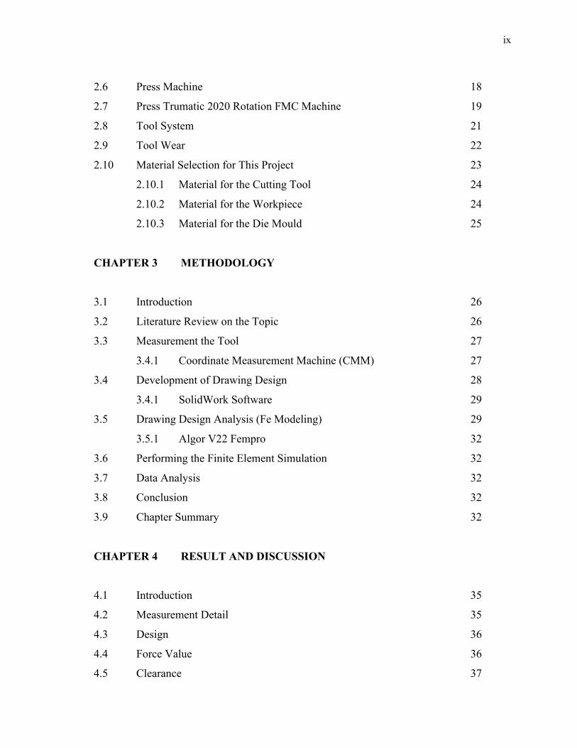
2.6 Press Machine 18
2.7 Press Trumatic 2020 Rotation FMC Machine 19
2.8 Tool System 21
2.9 Tool Wear 22
2.10 Material Selection for This Project 23
2.10.1 Material for the Cutting Tool 24
2.10.2 Material for the Workpiece 24
2.10.3 Material for the Die Mould 25
CHAPTER 3 METHODOLOGY
3.1 Introduction 26
3.2 Literature Review on the Topic 26
3.3 Measurement the Tool 27
3.4.1 Coordinate Measurement Machine (CMM) 27
3.4 Development of Drawing Design 28
3.4.1 SolidWork Software 29
3.5 Drawing Design Analysis (Fe Modeling) 29
3.5.1 Algor V22 Fempro 32
3.6 Performing the Finite Element Simulation 32
3.7 Data Analysis 32
3.8 Conclusion 32
3.9 Chapter Summary 32
CHAPTER 4 RESULT AND DISCUSSION
4.1 Introduction 35
4.2 Measurement Detail 35
4.3 Design 36
4.4 Force Value 36
4.5 Clearance 37
x
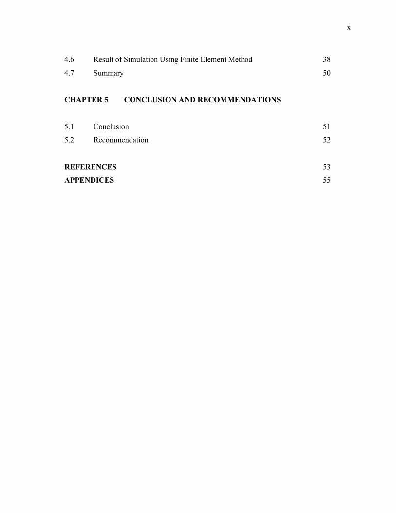
4.6 Result of Simulation Using Finite Element Method 38
4.7 Summary 50
CHAPTER 5 CONCLUSION AND RECOMMENDATIONS
5.1 Conclusion 51
5.2 Recommendation 52
REFERENCES 53
APPENDICES 55
xi
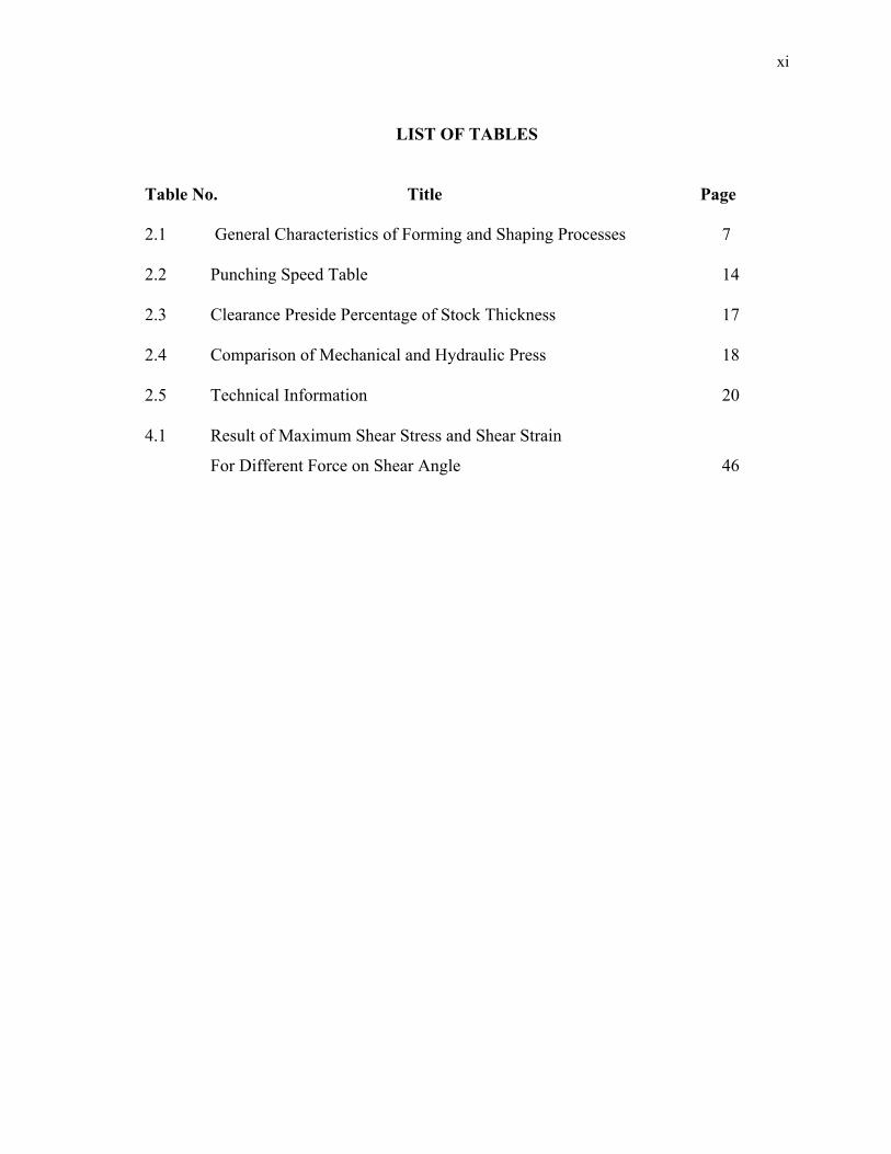
LIST OF TABLES
Table No. Title Page
2.1 General Characteristics of Forming and Shaping Processes 7
2.2 Punching Speed Table 14
2.3 Clearance Preside Percentage of Stock Thickness 17
2.4 Comparison of Mechanical and Hydraulic Press 18
2.5 Technical Information 20
4.1 Result of Maximum Shear Stress and Shear Strain
For Different Force on Shear Angle 46
xii
LIST OF FIGURES
Figure No. Title Page
1.1 Geometry of sheared workpiece 4
2.1 Punching and Blanking Processes 10
2.2 Die cutting process 10
2.3 Stress- Strain Graph 12
2.4 Process of Shearing 13
2.5 The Clearance in the Punching Process 16
2.6 Press Trumatic 2020 Rotation FMC Machine 20
2.7 Tool System 21
3.1 Coordinate Measurement Machine (CMM) 27
3.2 The initial geometry of the insert according to the actual punch tool 30
3.3 Idealized punching process 31
3.4 The complete FE model consists of tool, dies and sheet metal 31
3.5 Summary on Methodology 34
4.1 Tool model draw using SolidWork 36
4.2 The Clearance for the FE Model 37
4.3 Result of Stress Tensor Y-Y for tool with 4.5o for 60kN force 38
4.4 Result of Strain Tensor Y-Y for tool with 4.5o for 60kN force 38
4.5 Result of Stress Tensor Y-Y for tool with 4.5o for 90kN force 39
4.6 Result of Strain Tensor Y-Y for tool with 4.5o for 90kN force 40
4.7 Result of Stress Tensor Y-Y for tool with 4.5o for 120kN force 41

xiii
4.8 Result of Strain Tensor Y-Y for tool with 4.5o for 120kN force 41
4.9 Result of Stress Tensor Y-Y for tool with 4.5o for 150kN force 42
4.10 Result of Strain Tensor Y-Y for tool with 4.5o for 150kN force 43
4.11 Result of Stress Tensor Y-Y for tool with 4.5o for 180kN force 44
4.12 Result of Strain Tensor Y-Y for tool with 4.5o for 180kN force 44
xiv
LIST OF SYMBOLS/ABBREVIATIONS
SYMBOL
σ
P
Ao
l
lo
E
e
V
D
F
T
Y
c
D and d
UTS
CAD
IGES
Engineering Stress
Load
Cross sectional area
Instantaneous Length
Initial Length
Modulus of elasticity
Engineering Strain
cutting speed
depth of cut
feed rate
Thickness of sheet metal
Yield Strength
clearance
die and punch diameter
Ultimate tensile Strength
computer-aided design
Initial Graphics Exchange Specification
xv
LIST OF APPENDICES
Appendix Title Page
I Assab Steels ASP 23 Cold Work Steel Properties 55
II Aluminum, Al Properties 60
III AISI 4130 Steel, normalized at 870°C (1600°F) Properties 62
IV Design of Slitting Insert 64
CHAPTER 1
INTRODUCTION
1.1 PROJECT BACKGROUND
The research work in this project involves a theoretical investigation the effect of
shear angle on high speed steel (HSS) punching tool in punching process. The project will
be carried out to determine the effect of different shear angle on High Speed Steel (HSS)
punching tool in punching process using Finite Element Method (FEM) based on punching
process using Press Trumatic 2020 Rotation FMC Machine (Trumpf TruPunch 2020R).
The result will show what the effect of different shear angle on the HSS punching tool
while in punching process and the optimum shear angle.
Nowadays, CNC punching machine have been used to fabricate the product from
sheet metal where the process is fully under computer controlled with preparing NC
program. The technology in cutting process improve day by day rapidly which have plasma
cutting, laser cutting, turret punch and etc.. Different type of machine, it will conduct
different but same of basic.
Tool system is very important in machining process. Complete tool set contain
punch, alignment ring, stripper and die. If one of these components not conducts wisely it
will damage the product or will facing with machine damage. To sure the product is high
quality and the process of manufacture can conduct safely, the quality of punch component
especially tooling is very important. Punch is come in three designs which are flat punch,
2
punch with roof shear and angled punch. Better tool is defined as strength of wear
resistance and toughness in one grade.
1.2 OBJECTIVE
1.2.1 Investigate the effect of shear angle on Turret Punch Insert using finite
element analysis.
1.2.2 To choose the optimum shear angle of Turret Punch Insert using finite
element analysis.
1.3 SCOPES
This project only considers on investigating of the effect different shear angle and
the best shear angle of high speed steel punching tool. It will start with literature review and
understands the statement of problem. After that, it will follow by the measuring the actual
tool using Coordinate Measuring Machine. Next, from the actual measurement, the tool is
developing with different shear angle by designing with CAD software, SolidWorks. The
climax of the project is simulating the model using Finite element Software, ALGOR V22
Fempro. Lastly, the results from the simulation will use to analyze the effect of different
shear angle by plotting the graph.
3
1.4 PROBLEM STATEMENT
Challenging for tooling manufacturer is how to use their tool on hard machine for
fabricating on soft metal. So they will think which material is the best in term of costing,
quality of the product and time consideration. Thus they will think how the defect will
occur. The factor that will define is work piece and tool material, punch geometry, sheet
metal thickness and clearance. In this project just will consider on punch geometry (shear
angle). The concept used in this project is connected with pressure and theory of energy.
Even by giving same force but the pressure will change due to contact with surface area. In
addition, by changing the shear angle of the tool, it hopes tool life will be improved. This is
because selection of right shear angle or generally, punch geometry is very important for
tool life and the final product. So, improvement of tool life is very important because tool
will often facing adhesive and abrasive wear in contact zone. In addition, tool will affect
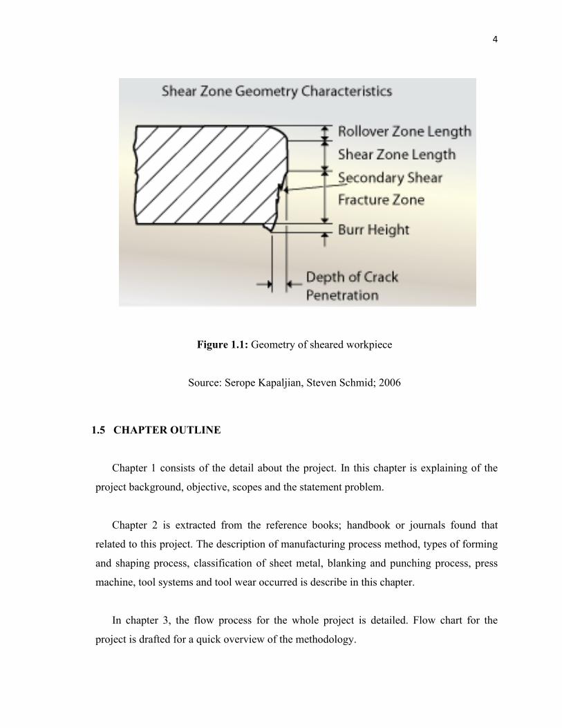
dimensional and form error. As in phase process of shearing, after given the force, work
piece will in plastic phase and then will reach fracture limit and micro cracks will appear
which turn onto macro cracks. As a result the edge will not appear smoothly by appearing
the burr as shown in Figure 1.1. The productivity and quality in sheet metal can be assessed
by the burr height after blanking process. Accordingly to geometry of punch, this project
will investigate the effect of shear angle. (Serope Kapaljian, Steven Schmid; 2006,
R.Hambli; 2001)
4
Figure 1.1: Geometry of sheared workpiece
Source: Serope Kapaljian, Steven Schmid; 2006
1.5 CHAPTER OUTLINE
Chapter 1 consists of the detail about the project. In this chapter is explaining of the
project background, objective, scopes and the statement problem.
Chapter 2 is extracted from the reference books; handbook or journals found that
related to this project. The description of manufacturing process method, types of forming
and shaping process, classification of sheet metal, blanking and punching process, press
machine, tool systems and tool wear occurred is describe in this chapter.
In chapter 3, the flow process for the whole project is detailed. Flow chart for the
project is drafted for a quick overview of the methodology.
5
Chapter 4 provides all the data collected. It started with measurement on the actual
insert and develops the design using SolidWorks by changing the shear angle of the insert.
The next step is develop finite element model using ALGOR V22 Fempro, and lastly
simulate the model using ALGOR V22 Fempro. It’s also includes discussion of the finding
data.
Lastly in Chapter 5, the whole project is concluded and some recommendation. The
conclusion based on the project objective and the recommendation is for improvement for
further study.
CHAPTER 2
LITERATURE REVIEW
2.1 INTRODUCTION
The science, engineering and technology of manufacturing process and systems
continue to move on speedily on a worldwide scale and with major impact on the financial
systems of all peoples. This is because with this condition people can invent many products
with various shapes. As a result, that science, engineering and technology of manufacturing
processes and system people can do many things.
With knowledge of manufacturing, till today many kinds of manufacturing have
been generated. To produce parts, need variety of manufacturing processes. The broad
groups of the handing routine for materials base are follows; ((Serope Kapaljian, Steven
Schmid; 2006)
Casting-expendable mold and permanent mold
i. Forming and shaping- rolling, forging, extrusion, drawing, sheet forming, powder
metallurgy and molding.
ii. Machining- turning, boring, drilling, milling, shaping, broaching and grinding,
ultrasonic machining; chemical, electrical, and electrochemical machining; and
high- energy- beam machining.
7
iii. Joining- welding, brazing, soldering, diffusion bonding, adhesive bonding and
mechanical joining.
iv. Finishing- honing, lapping, burnishing, deburring, surface treating, coating, and
plating.
v. Nanofabrication is the most advanced technology and is capable of producing parts
with dimensions at the nano level (one- billionth); it typically involves processes
such as etching techniques, electron- beams, and laser beams. Present applications
are in the fabrication of microelectromechanical systems (NEMS), which operate on
the same scale as biological molecules.
2.2 FORMING AND SHAPING PROCESSES
Forming and shaping process is one of manufacturing process which some of the
product can replace function of casting process. It can reduce the cost. As in Manufacturing
Engineering and Technology told that about the characteristics every types process that in
categories forming and shaping as shown in Table 2.1.
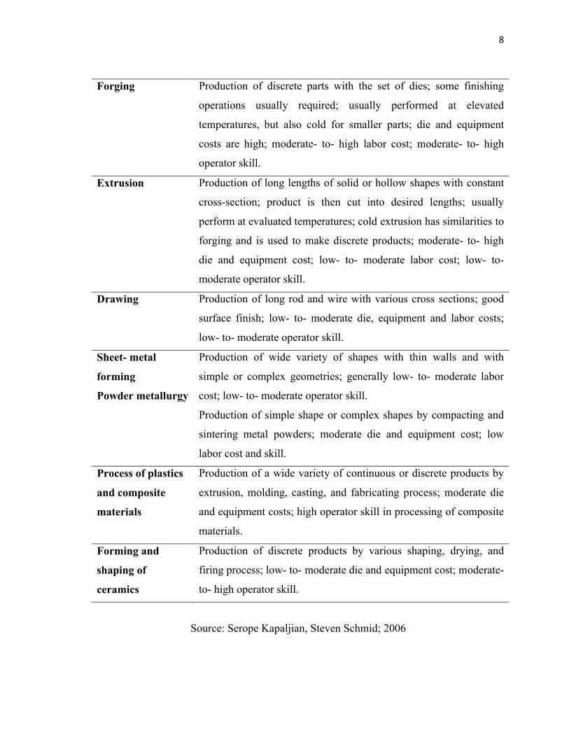
Table 2.1: General Characteristics of Forming and Shaping Processes
General Characteristic of Forming and Shaping Process
Process Characteristics
Rolling
Flat
Shape
Production of flat plate, sheet and foil at high speeds; good surface
finish, especially in cold rolling; very high capital investment; lot-
to- moderate labor cost.
Production of various structural shapes (such as I- beam and rails)
at high speeds; includes thread rolling; requires shaped roll and
expensive equipment; low- to- moderate labor cost; moderate
operator skill.
8
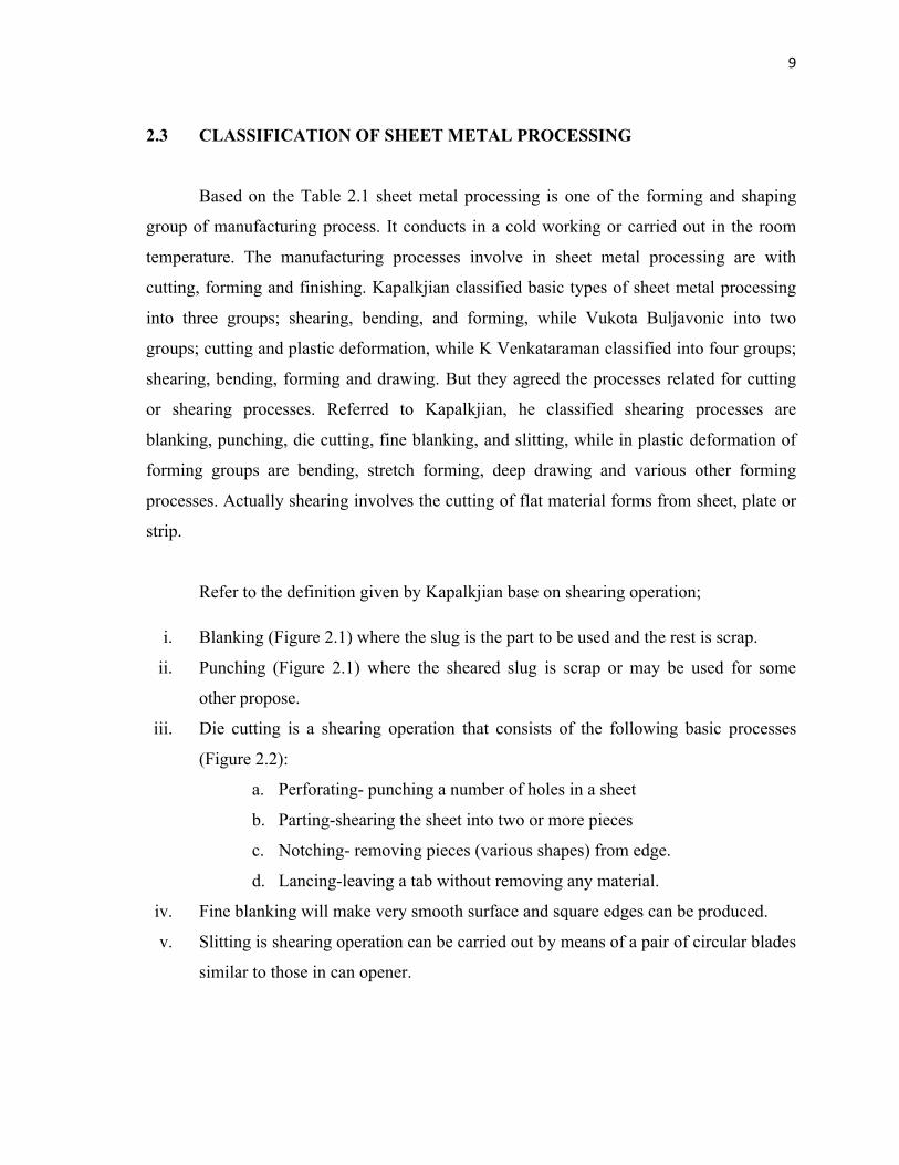
Forging Production of discrete parts with the set of dies; some finishing
operations usually required; usually performed at elevated
temperatures, but also cold for smaller parts; die and equipment
costs are high; moderate- to- high labor cost; moderate- to- high
operator skill.
Extrusion Production of long lengths of solid or hollow shapes with constant
cross-section; product is then cut into desired lengths; usually
perform at evaluated temperatures; cold extrusion has similarities to
forging and is used to make discrete products; moderate- to- high
die and equipment cost; low- to- moderate labor cost; low- to-
moderate operator skill.
Drawing Production of long rod and wire with various cross sections; good
surface finish; low- to- moderate die, equipment and labor costs;
low- to- moderate operator skill.
Sheet- metal
forming
Powder metallurgy
Production of wide variety of shapes with thin walls and with
simple or complex geometries; generally low- to- moderate labor
cost; low- to- moderate operator skill.
Production of simple shape or complex shapes by compacting and
sintering metal powders; moderate die and equipment cost; low
labor cost and skill.
Process of plastics
and composite
materials
Production of a wide variety of continuous or discrete products by
extrusion, molding, casting, and fabricating process; moderate die
and equipment costs; high operator skill in processing of composite
materials.
Forming and
shaping of
ceramics
Production of discrete products by various shaping, drying, and
firing process; low- to- moderate die and equipment cost; moderate-
to- high operator skill.
Source: Serope Kapaljian, Steven Schmid; 2006
9
2.3 CLASSIFICATION OF SHEET METAL PROCESSING
Based on the Table 2.1 sheet metal processing is one of the forming and shaping
group of manufacturing process. It conducts in a cold working or carried out in the room
temperature. The manufacturing processes involve in sheet metal processing are with
cutting, forming and finishing. Kapalkjian classified basic types of sheet metal processing
into three groups; shearing, bending, and forming, while Vukota Buljavonic into two
groups; cutting and plastic deformation, while K Venkataraman classified into four groups;
shearing, bending, forming and drawing. But they agreed the processes related for cutting
or shearing processes. Referred to Kapalkjian, he classified shearing processes are
blanking, punching, die cutting, fine blanking, and slitting, while in plastic deformation of
forming groups are bending, stretch forming, deep drawing and various other forming
processes. Actually shearing involves the cutting of flat material forms from sheet, plate or
strip.
Refer to the definition given by Kapalkjian base on shearing operation;
i. Blanking (Figure 2.1) where the slug is the part to be used and the rest is scrap.
ii. Punching (Figure 2.1) where the sheared slug is scrap or may be used for some
other propose.
iii. Die cutting is a shearing operation that consists of the following basic processes
(Figure 2.2):
a. Perforating- punching a number of holes in a sheet
b. Parting-shearing the sheet into two or more pieces
c. Notching- removing pieces (various shapes) from edge.
d. Lancing-leaving a tab without removing any material.
iv. Fine blanking will make very smooth surface and square edges can be produced.
v. Slitting is shearing operation can be carried out by means of a pair of circular blades
similar to those in can opener.