inverter/charger - grid-interactive · t he grid-interactive renewable energy systems enable you to...
TRANSCRIPT

The Grid-Interactive renewable energy systems enable you to demonstrate your personal commitment to a renewable energy future. With the OutBack grid-interactive system,
backup AC power is made available 24 hours a day in the event of a utility outage, providing reliable power and peace-of-mind. At night, the inverter's automatic power save mode ensures that energy is not wasted by needlessly charging your batteries from the utility grid. An average conversion efficiency of 91% using the California Energy Commission (CEC) test protocol provides greater savings and a shorter time period for system payback. OutBack's grid-interactive technology provides you more than a typical solar inverter, we also have an unmatched ability to utilize solar, wind and hydropower sources.
OutBack inverter/chargers are designed to provide clean, reliable, true sine wave back-up power that seamlessly works with any equipment without the electrical buzzing associated with modified sine wave inverters (some equipment will not work at all). In the event of a utility power outage, our equipment
provides virtually instantaneous transfer to battery back-up power.The OutBack inverter/charger is designed to work with larger battery banks providing much longer run times than traditional uninterruptible power supplies (UPS’s). Our robust design allows our system to work in conjunction with generators that often output very low quality power to provide even longer run times (several days or longer) with the added benefit of greatly reducing the generator’s fuel consumption. All of our inverters are protected in rugged, cast aluminum housings, and the sealed models offers another level of protection in harsh environments
GFX Sealed Inverters/Chargers
The OutBack true sinewave GFX International Series Inverter/Charger is a competitive power solution designed for applications with lower power demands. Incorporating a DC-to-AC sinewave inverter, battery charger and AC transfer relay housed within a die-cast aluminum chassis, the International Series GFX Inverter/Chargers give you the ability to sell solar, wind or hydro power back to the utility grid while providing instantaneous back-up power in the event of a utility outage
SpecificationsSealed models Vented Models
GTFX2524 GTFX3048 GVFX3524 GVFX3648
Nominal DC Input Voltage 24 VDC 48 VDC 24 VDC 48 VDC
Continuous Power Rating at 25° C 2500 VA 3000 VA 3500 VA 3600 VA
AC Voltage/Frequency 120 VAC 60 Hz 120 VAC 60 Hz 120 VAC 60 Hz 120 VAC 60 Hz
Continuous AC RMS Output at 25° C 20.8 amps AC 25.0 amps AC 29.2 amps AC 30.0 amps AC
Idle Power Full ≈ 20 Watts ≈ 20 Watts ≈ 20 Watts ≈ 20 Watts
Search ≈ 6 Watts ≈ 6 Watts ≈ 6 Watts ≈ 6 Watts
Typical Efficiency 92% 93% 92% 93%
Total Harmonic Distortion Inverting 2% 2% 2% 2%
Selling 5% 5% 5% 5%
Output Voltage Regulation ± 2% ± 2% ± 2% ± 2%
Maximum Output Current Peak 70 amps AC 70 amps AC 70 amps AC 70 amps AC
RMS 50 amps AC 50 amps AC 50 amps AC 50 amps AC
AC Overload Capability Surge 6000 VA 6000 VA 6000 VA 6000 VA
Second 4800 VA 4800 VA 5000 VA 5000 VA
30 Minutes 3200 VA 3200 VA 4000 VA 4000 VA
AC Input Current Maximum 60 amps AC 60 amps AC 60 amps AC 60 amps AC
AC Input Voltage Range (MATE Adjustable) 80 to 150 VAC 80 to 150 VAC 80 to 150 VAC 80 to 150 VAC
AC Input Frequency Range 58 to 62 Hz 58 to 62 Hz 58 to 62 Hz 58 to 62 Hz
DC Input Range 21.0 to 34.0 VDC 42.0 to 68.0 VDC
21.0 to 34.0 VDC
42.0 to 68.0 VDC
Continuous Battery Charge Output 55 amps DC 35 amps DC 85 amps DC 45 amps DC
Warranty Standard 2 year / Optional 5 year Standard 2 year / Optional 5 year
Weight Unit 56 lbs (25 kg) 54 lbs (25 kg)
Shipping 67 lbs (30 kg) 62.2 lbs (28 kg)
Dimensions (H x W x L) Unit 13 x 8.25 x 16.25” (33 x 21 x 41 cm)
12 x 8.25 x 16.25” (30 x 21 x 41 cm)
Shipping 21.75 x 13 x 22” (55 x 33 x 56 cm) 21.75 x 13 x 22” (55 x 33 x 56 cm)
Inverter/Charger - Grid-Interactive
GTFX and GVFX
Johannesburg BranchPhone: 011 462-4253 / 4254 / 4269 / 0390 / 0448 / 1031 / 1620 / 2310 / 2425 / 2503 / 2600
Sealed GTFXSine wave Output
Grid-Interactive
Intelligent Battery
Charging
Modular Stackable
Design
High Operating
Efficiency
Weather-resistant
Sealed Chases
Corrosion Resistant
Internal Components
Field Serviceable
Integrated Network
Communications
Vented GVFXSine wave Output
Grid-Interactive
Intelligent Battery
Charging
High Operating
Efficiency
“Bug-proof” Chassis
Corrosion Resistant
internal Components
Field Serviceable
Integrated Network
Communications
Stackable Design conceptA single inverter
can supply up
to 3.6 kW with a
48V battery and
additional inverters
can be “stacked” to
provide up to 36kW
with 230V, 50Hz
units). The inverters
can be used in
single phase, split
phase or three
phase configuration.
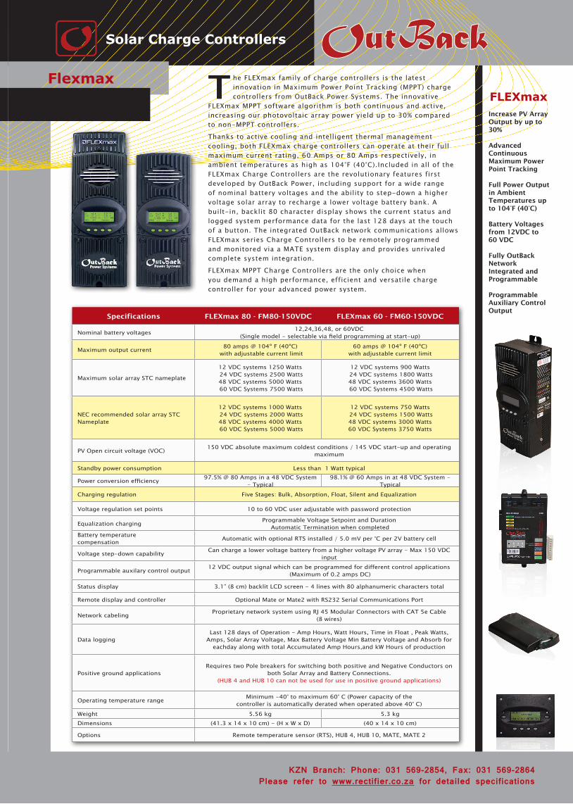
The FLEXmax family of charge controllers is the latest innovation in Maximum Power Point Tracking (MPPT) charge controllers from OutBack Power Systems. The innovative
FLEXmax MPPT software algorithm is both continuous and active, increasing our photovoltaic array power yield up to 30% compared to non-MPPT controllers.
Thanks to active cooling and intelligent thermal management cooling, both FLEXmax charge controllers can operate at their full maximum current rating, 60 Amps or 80 Amps respectively, in ambient temperatures as high as 104°F (40°C).Included in all of the FLEXmax Charge Controllers are the revolutionary features first developed by OutBack Power, including support for a wide range of nominal battery voltages and the ability to step-down a higher voltage solar array to recharge a lower voltage battery bank. A built-in, backlit 80 character display shows the current status and logged system performance data for the last 128 days at the touch of a button. The integrated OutBack network communications allows FLEXmax series Charge Controllers to be remotely programmed and monitored via a MATE system display and provides unrivaled complete system integration.
FLEXmax MPPT Charge Controllers are the only choice when you demand a high performance, efficient and versatile charge controller for your advanced power system.
Specifications FLEXmax 80 - FM80-150VDC FLEXmax 60 - FM60-150VDC
Nominal battery voltages 12,24,36,48, or 60VDC (Single model - selectable via field programming at start-up)
Maximum output current 80 amps @ 104º F (40ºC) with adjustable current limit
60 amps @ 104º F (40ºC) with adjustable current limit
Maximum solar array STC nameplate
12 VDC systems 1250 Watts 24 VDC systems 2500 Watts 48 VDC systems 5000 Watts 60 VDC Systems 7500 Watts
12 VDC systems 900 Watts 24 VDC systems 1800 Watts 48 VDC systems 3600 Watts 60 VDC Systems 4500 Watts
NEC recommended solar array STC Nameplate
12 VDC systems 1000 Watts 24 VDC systems 2000 Watts 48 VDC systems 4000 Watts 60 VDC Systems 5000 Watts
12 VDC systems 750 Watts 24 VDC systems 1500 Watts 48 VDC systems 3000 Watts 60 VDC Systems 3750 Watts
PV Open circuit voltage (VOC) 150 VDC absolute maximum coldest conditions / 145 VDC start-up and operating maximum
Standby power consumption Less than 1 Watt typical
Power conversion efficiency 97.5% @ 80 Amps in a 48 VDC System - Typical
98.1% @ 60 Amps in at 48 VDC System - Typical
Charging regulation Five Stages: Bulk, Absorption, Float, Silent and Equalization
Voltage regulation set points 10 to 60 VDC user adjustable with password protection
Equalization charging Programmable Voltage Setpoint and Duration Automatic Termination when completed
Battery temperature compensation Automatic with optional RTS installed / 5.0 mV per °C per 2V battery cell
Voltage step-down capability Can charge a lower voltage battery from a higher voltage PV array - Max 150 VDC input
Programmable auxilary control output 12 VDC output signal which can be programmed for different control applications (Maximum of 0.2 amps DC)
Status display 3.1” (8 cm) backlit LCD screen - 4 lines with 80 alphanumeric characters total
Remote display and controller Optional Mate or Mate2 with RS232 Serial Communications Port
Network cabeling Proprietary network system using RJ 45 Modular Connectors with CAT 5e Cable (8 wires)
Data loggingLast 128 days of Operation - Amp Hours, Watt Hours, Time in Float , Peak Watts,
Amps, Solar Array Voltage, Max Battery Voltage Min Battery Voltage and Absorb for eachday along with total Accumulated Amp Hours,and kW Hours of production
Positive ground applicationsRequires two Pole breakers for switching both positive and Negative Conductors on
both Solar Array and Battery Connections. (HUB 4 and HUB 10 can not be used for use in positive ground applications)
Operating temperature range Minimum -40° to maximum 60° C (Power capacity of thecontroller is automatically derated when operated above 40° C)
Weight 5.56 kg 5.3 kgDimensions (41.3 x 14 x 10 cm) - (H x W x D) (40 x 14 x 10 cm)
Options Remote temperature sensor (RTS), HUB 4, HUB 10, MATE, MATE 2
Flexmax
Solar Charge Controllers
FLEXmaxIncrease PV Array Output by up to 30%
Advanced Continuous Maximum Power Point Tracking
Full Power Output in Ambient Temperatures up to 104°F (40°C)
Battery Voltages from 12VDC to 60 VDC
Fully OutBack Network Integrated and Programmable
Programmable Auxiliary Control Output
KZN Branch: Phone: 031 569-2854, Fax: 031 569-2864Please refer to www.rectifier.co.za for detailed specifications
The OutBack Power Systems FLEXnet™ DC is the ultimate in DC System monitoring devices. Our integrated networked
communications make valuable, usable data available from your system, viewable on an OutBack MATE communications device (screens seen below), providing you with the answers you need concerning your system’s health, performance and efficiency.
The HUB system communications managers are the backbone of your networked OutBack power conversion system. The OutBack HUB communicates stacking, load share and power save off/on signals. Interconnection cabling is standard Ethernet CAT5 with RJ45 modular jacks. Through the use of a HUB, your system is completely coordinated and managed by the MATE.
M ATE & MATE2The MATE system display and controllers are complete management tools for your OutBack Power system. Through the use of a single MATE you can remotely manage and monitor multiple inverter/
chargers, MX60s and any future OutBack power conversion and control products. The MATE and MATE2 are packed full of features to make system management simple. The easy-to-read 3.1" (8 cm) LCD is backlit for dark operating conditions. Four soft keys allow easy context-based navigation of menus and functions. Two hot keys give immediate access to AC and inverter functions. A built-in clock and calendar function enables timer based programming of inverter and charger operation. This permits you to set the system to work with time-of-day power rates or to limit a generator's run time to a specific time period of the day or week. All of your settings are stored in permanent memory to eliminate the need to reprogram in the event of a system shutdown or battery replacement. The MATE and MATE2 include a RS232 port with DB9 jack for connection to the serial port of a PC computer. Through the use of optional WinVerter software you can perform such operations as data logging and graphical display of the system's operation and performance. The MATE system display and controller is surface mounted while the MATE2 is flush mountable in a wall cut-out.
T he new MATE 3 System Display and Controller makes it easier than ever to program and monitor your complete OutBack Power system. An intuitive user interface and integrated system configuration wizard make system setup and programming quick and seamless. The ability to set unique multi-level user passwords allows you to
secure critical system settings from unintended changes while still allowing open access to necessary functions. Through the use of a single MATE3 you can remotely manage and monitor multiple inverter/chargers, charge controllers an DC monitoring devices.
FN-DC Specifications
Battery voltage input 8.0 to 80.0 Volts DC
Battery voltage resolution 0.1 Volts DC
Number of current channels One to three (each can be source or load)
Current Resolution 0.1 Amps DC
State of charge display 0 to 100% (1% increments)
Aux Relay configuration SPST, Magnetic Latching Relay
Aux Relay max. rating 5Amps @ 30 Volts DC
Current shunt type 500 Amp / 50mV
FN-DC Specifications
DisplayPrimary Mate or Mate2; 4x 20 LCD
Secondary 5 LED Indicators on front of FLEXnet DC
Battery Ah capacity range 100 to 10,000 Amp Hours
Data logging memory Most recent 128 days
Programmable aux. relay settings
Battery Volts Adj. 8.0 to 80.0 VDC
S.O.C Adj. from 0 to 100%
Time Delay Adj. from 0 to 240 Min.
Operating temp. range 0 - 50º C
Advanced DC System Monitor
FLEXnet DC, Hub Communication Manager & Mate
Mate
Tempera-ture
Sensor
FLEX power
Please refer to www.rectifier.co.za for detailed specifications.JHB Phone: 011 462-4253 Fax: 011 462-4310 KZN Phone: 031 569-2854 Fax: 031 569-2864
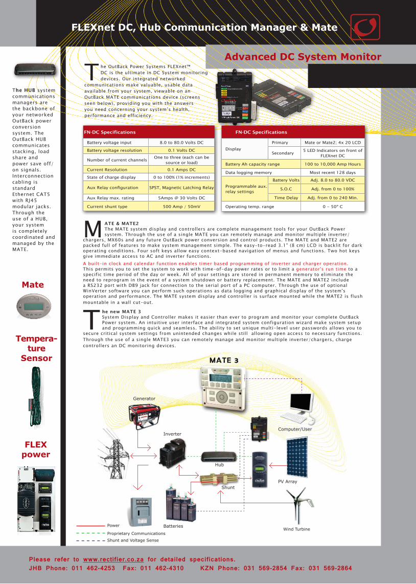
Computer/User
PV Array
Wind Turbine
Hub
Shunt
Inverter
Generator
BatteriesPower
Proprietary CommunicationsShunt and Voltage Sense