inverter mini chiller (acson) selling... · air-cooled inverter mini chiller. ... • building load...
TRANSCRIPT
Technical Training 2007Technical Training 2007Technical Training 2007
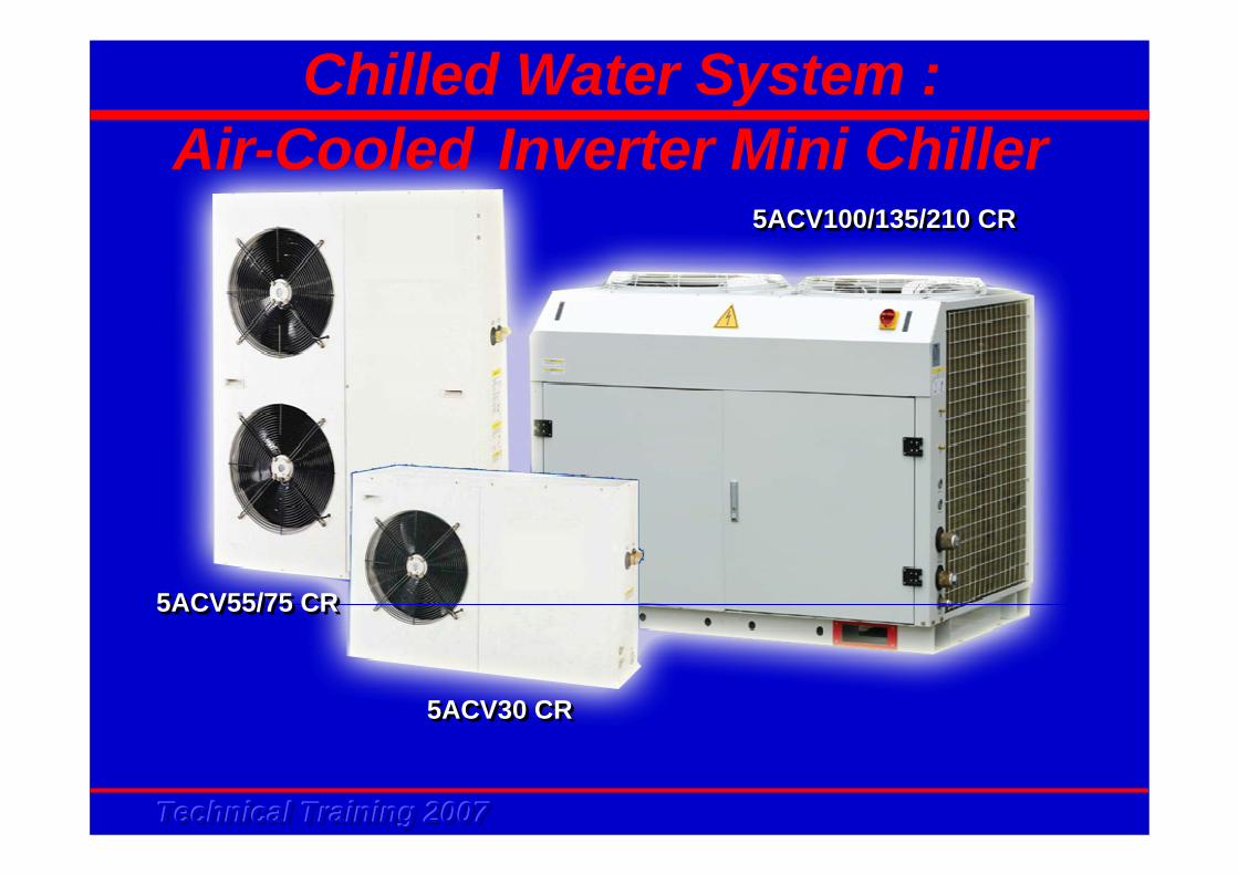
5ACV30 CR5ACV30 CR
5ACV55/75 CR5ACV55/75 CR
5ACV100/135/210 CR5ACV100/135/210 CR
Chilled Water System :Air-Cooled Inverter Mini Chiller
Technical Training 2007Technical Training 2007Technical Training 2007
System Schematic DiagramSystem Schematic DiagramAdvantages of Chilled Water SystemAdvantages of Chilled Water SystemProduct LineupProduct LineupDesign & ApplicationDesign & Application
Content
Product FeaturesProduct FeaturesSchematic Diagram & ComponentsSchematic Diagram & ComponentsInstallation & CommissioningInstallation & CommissioningSelf Diagnosis & TroubleshootingSelf Diagnosis & TroubleshootingSmart ManagerSmart ManagerSelection SoftwareSelection SoftwareCompetitorCompetitor’’s Products Comparisons Products Comparison
Technical Training 2007Technical Training 2007Technical Training 2007
System Schematic Diagram
Technical Training 2007Technical Training 2007Technical Training 2007
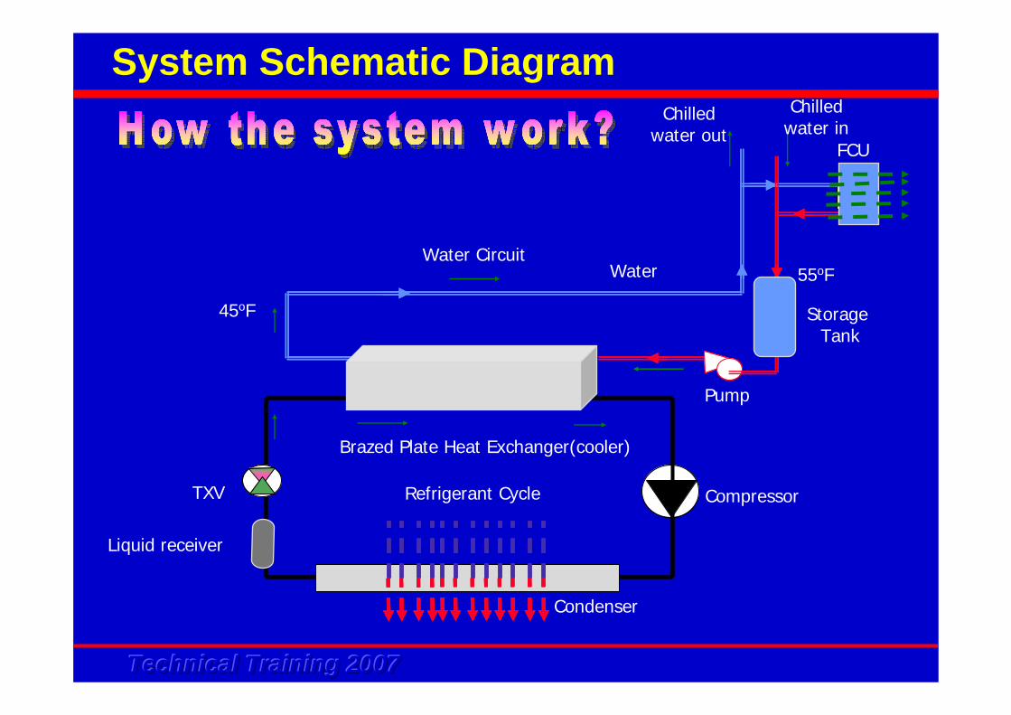
System Schematic Diagram
Brazed Plate Heat Exchanger(cooler)
Water
45oF
55oF
Refrigerant Cycle CompressorTXV
Liquid receiver
FCU
Storage Tank
Pump
Chilledwater out
Chilledwater in
Water Circuit
Condenser
Technical Training 2007Technical Training 2007Technical Training 2007
Advantages of Chilled Water
System
Technical Training 2007Technical Training 2007Technical Training 2007
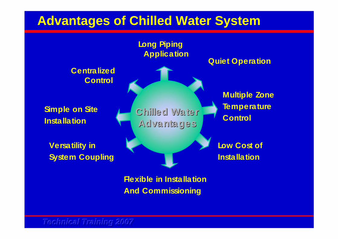
Quiet Operation
Simple on Site Installation
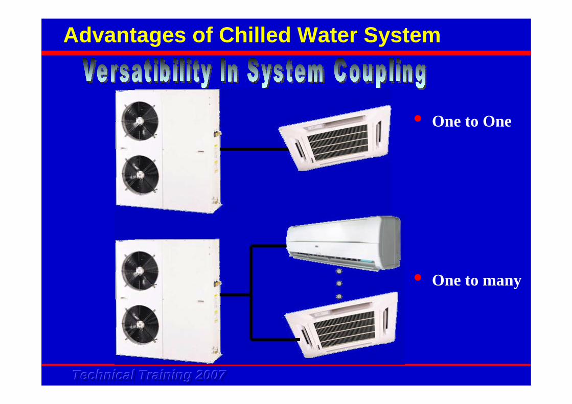
Versatility inSystem Coupling
Flexible in Installation And Commissioning
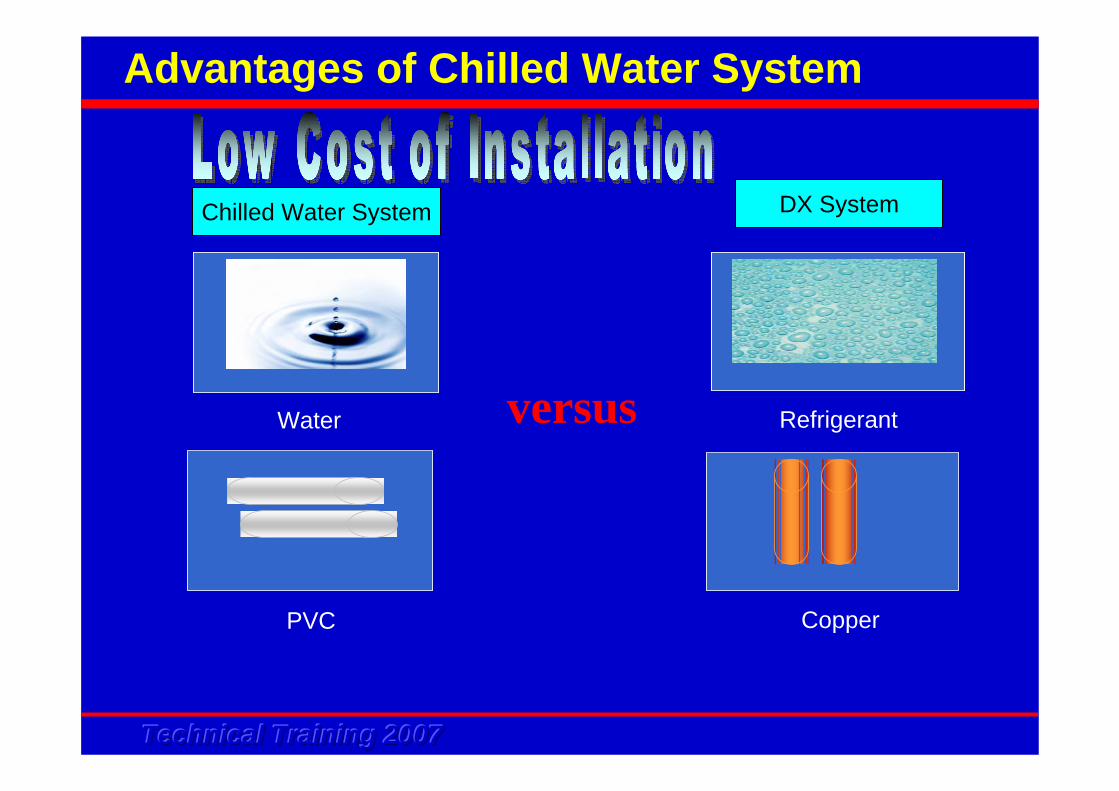
Low Cost of Installation
Chilled WaterChilled WaterAdvantagesAdvantages
Long Piping Application
Centralized Control
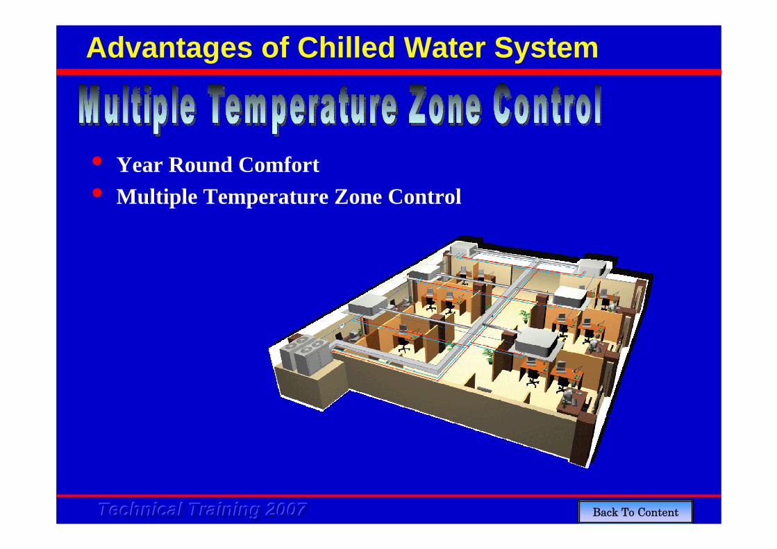
Multiple ZoneTemperatureControl
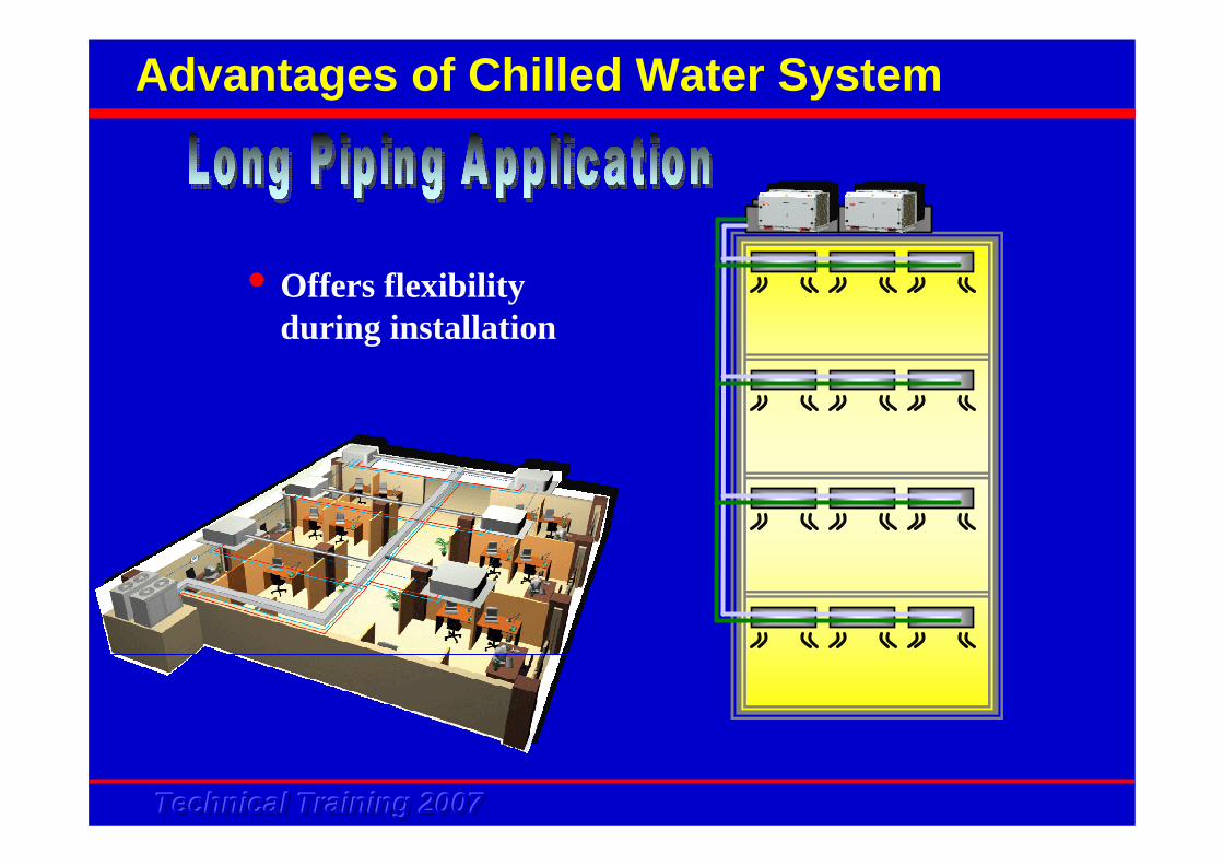
Advantages of Chilled Water System
Technical Training 2007Technical Training 2007Technical Training 2007
•Offers flexibility during installation
Advantages of Chilled Water System
Technical Training 2007Technical Training 2007Technical Training 2007
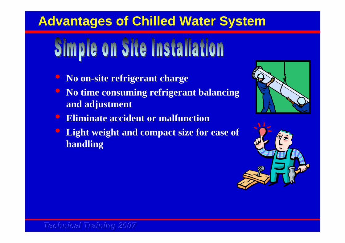
Advantages of Chilled Water System
• No on-site refrigerant charge• No time consuming refrigerant balancing
and adjustment• Eliminate accident or malfunction • Light weight and compact size for ease of
handling
Technical Training 2007Technical Training 2007Technical Training 2007
Advantages of Chilled Water System
• Quiet operation due to minimized outdoor units and mini chiller can be placed far away from room
Technical Training 2007Technical Training 2007Technical Training 2007
Advantages of Chilled Water System
• One to One
• One to many
Technical Training 2007Technical Training 2007Technical Training 2007
Advantages of Chilled Water System
versus
Chilled Water System DX System
Water
PVC
Refrigerant
Copper
Technical Training 2007Technical Training 2007Technical Training 2007
Advantages of Chilled Water System
• Year Round Comfort• Multiple Temperature Zone Control
Back To Content
Technical Training 2007Technical Training 2007Technical Training 2007
Product Lineup
Technical Training 2007Technical Training 2007Technical Training 2007
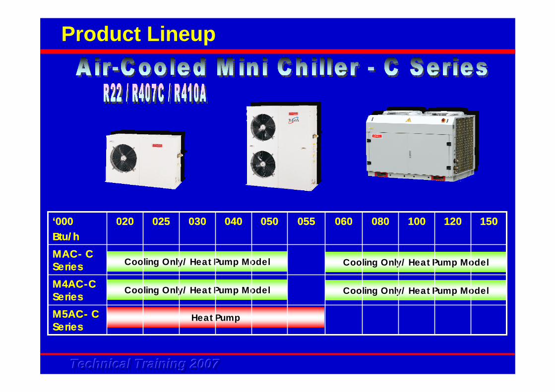
Product Lineup
Cooling Only/ Heat Pump Model Cooling Only/ Heat Pump Model
Cooling Only/ Heat Pump Model Cooling Only/ Heat Pump Model
Heat Pump
055
MAC- C SeriesM4AC-C Series
120100 150
M5AC- C Series
080060050040030025020‘000Btu/h
055
MAC- C SeriesM4AC-C Series
120100 150
M5AC- C Series
080060050040030025020‘000Btu/h
Technical Training 2007Technical Training 2007Technical Training 2007
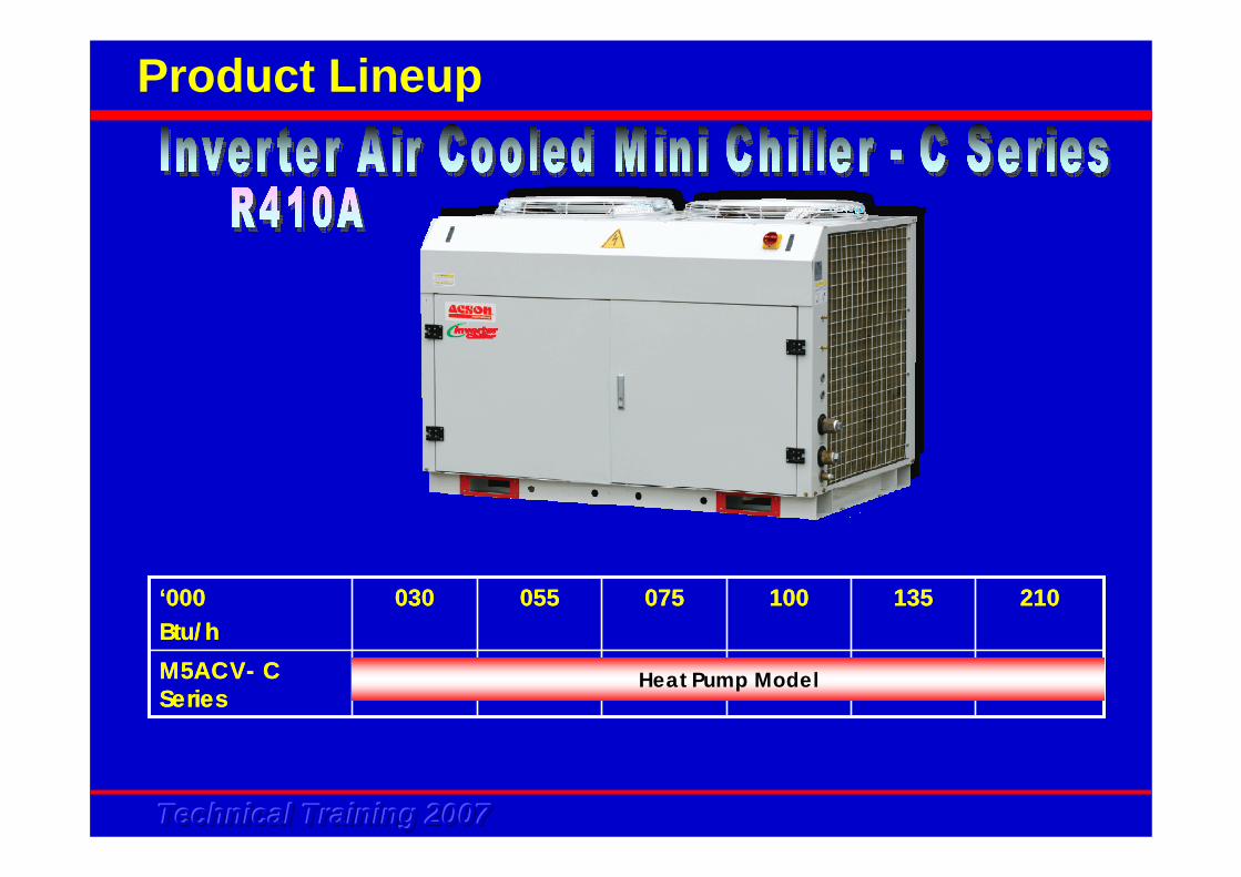
Product Lineup
M5ACV- C Series
210135100075055030‘000Btu/hM5ACV- C Series
210135100075055030‘000Btu/h
Heat Pump Model

Technical Training 2007Technical Training 2007Technical Training 2007
Design & Application

Technical Training 2007Technical Training 2007Technical Training 2007
Design & Application
• Understand Client’s requirement
• Application - feasible
• Installation/service-able
• Budget
• Inspection of job site
Technical Training 2007Technical Training 2007Technical Training 2007
Design & Application
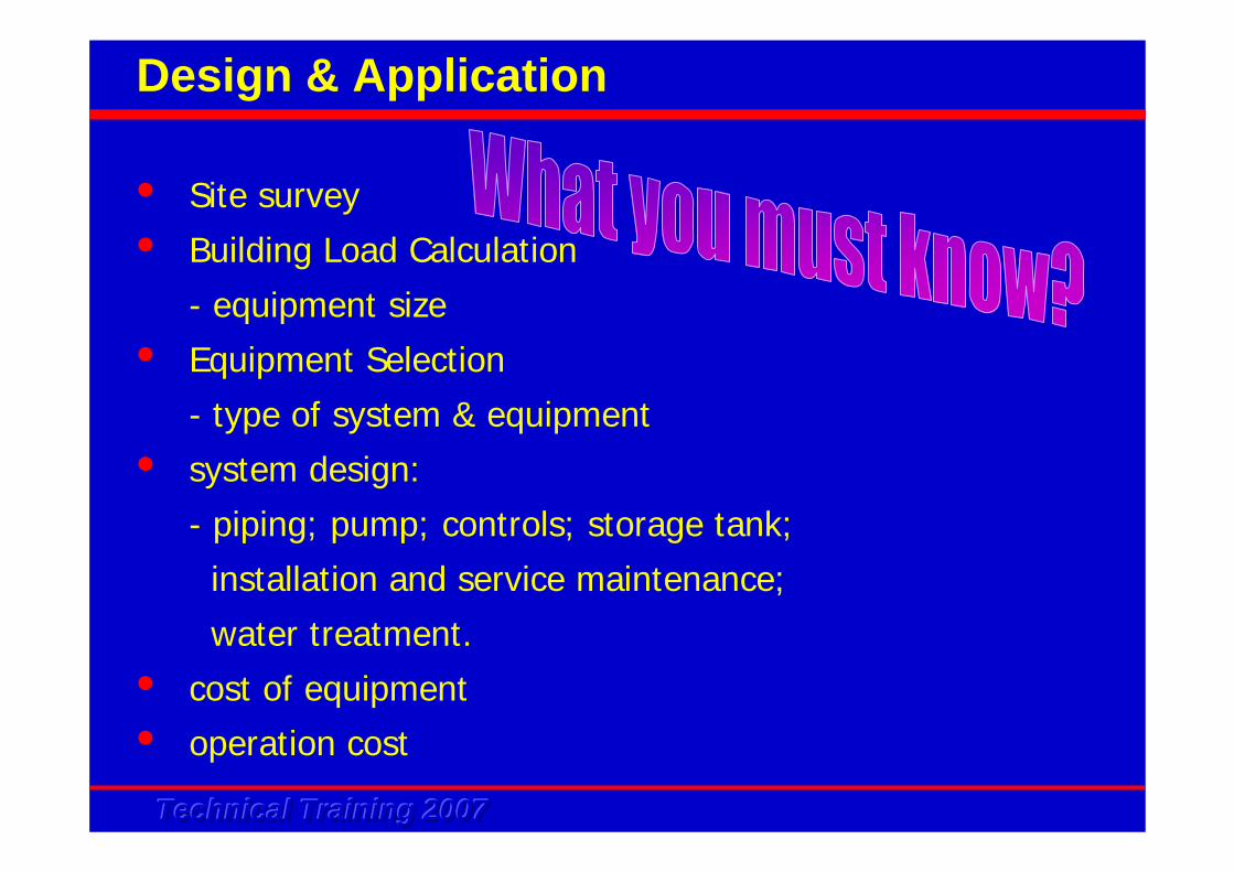
• Site survey
• Building Load Calculation
- equipment size
• Equipment Selection
- type of system & equipment
• system design:
- piping; pump; controls; storage tank;
installation and service maintenance;
water treatment.
• cost of equipment
• operation cost
Technical Training 2007Technical Training 2007Technical Training 2007
Design & Application
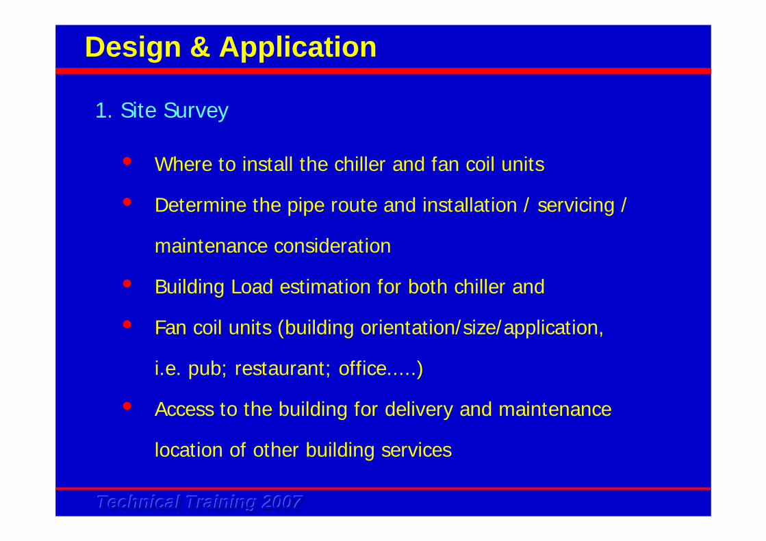
• Where to install the chiller and fan coil units
• Determine the pipe route and installation / servicing /
maintenance consideration
• Building Load estimation for both chiller and
• Fan coil units (building orientation/size/application,
i.e. pub; restaurant; office.....)
• Access to the building for delivery and maintenance
location of other building services
1. Site Survey

Technical Training 2007Technical Training 2007Technical Training 2007
Design & Application
OYL MANUFACTURING CO. SDN BHD COOLING LOAD ESTIMATIONPROJECT NAME : SK Bungalow DATE: 28/2/2001LOCATION : PenthouseAREA = 2000 HEIGHT = 15 NO.OF PEOPLE = 4CFM/PERSON= 15 VENT, CFM = 500 B.F. = 0.15ROOM TEMP = 75 ROOM RH% = TEMP DIFF. (ROOM & OUTDOOR) = 20 MOISTURE DIFF. = 80
GAIN/TD BTU/HR GAIN/TD BTU/HR
OUTDOOR TEMP CORRN= -2 0NE GLASS 600 0.76 45 20,520 22 10,032E GLASS 0.76 106 0 35 0SE GLASS 0.76 97 0 32 0S GLASS 0.76 10 0 8 0SW GLASS 600 0.76 30 13,680 91 41,496 W GLASS 0.76 44 0 132 0NW GLASS 0.76 28 0 75 0 N GLASS 0.76 11 0 11 0SHADED GLASS 0.76 11 0 11 0N WALL 0.49 1 0 13 0NE WALL 200 0.49 53 5,194 17 1,666E WALL 0.49 36 0 15 0SE WALL 600 0.49 16 4,704 16 4,704 S WALL 0.49 1 0 14 0SW WALL 200 0.49 1 98 30 2,940 W WALL 0.49 2 0 39 0NW WALL 600 0.49 1 294 33 9,702ROOF 2,000 0.23 6 2,760 38 17,480ALL GLS TRANSM 1,200 1.13 -2 (2,712) 0 0PARTITION 0.45 -2 0 0 0CEILING 0.3 0 0 0 0FLOOR 0.49 -7 0 -5 0PEOPLE,(S) 4 1 245 980 245 980POWER,KW 4 1 3414 13,656 3414 13,656LIGHTS,WATTS 2,000 1.25 3.414 8,535 3.414 8,535MISC.HEAT (S) 1 1 0 1 0SAFETY % (S) 5 3,385 5,560DT.GN/LK/FAN% 8 0 0OA HEAT(S)*BF 0 0PEOPLE,(L) 4 1 205 820 205 820MISC.HEAT (L) 1 1 0 1 0SAFETY % (L) 10 82 82DUCT LEAK% 8 0 0OA HEAT(L)*BF 4,080 4,080OA HEAT(S)1-BF 0 0OA HEAT(L)1-BF 23,120 23,120
GRAND TOTAL HEAT = 99,196 144,853COOLING TONS = 8.27 12.07ROOM SENSIBLE HEAT = 71,094 116,751TOTAL OA HEAT = 27,200 27,200
4.00PM SEP/MARAREA/QTYITEM FACTORS 10.00 AM SEP/MAR
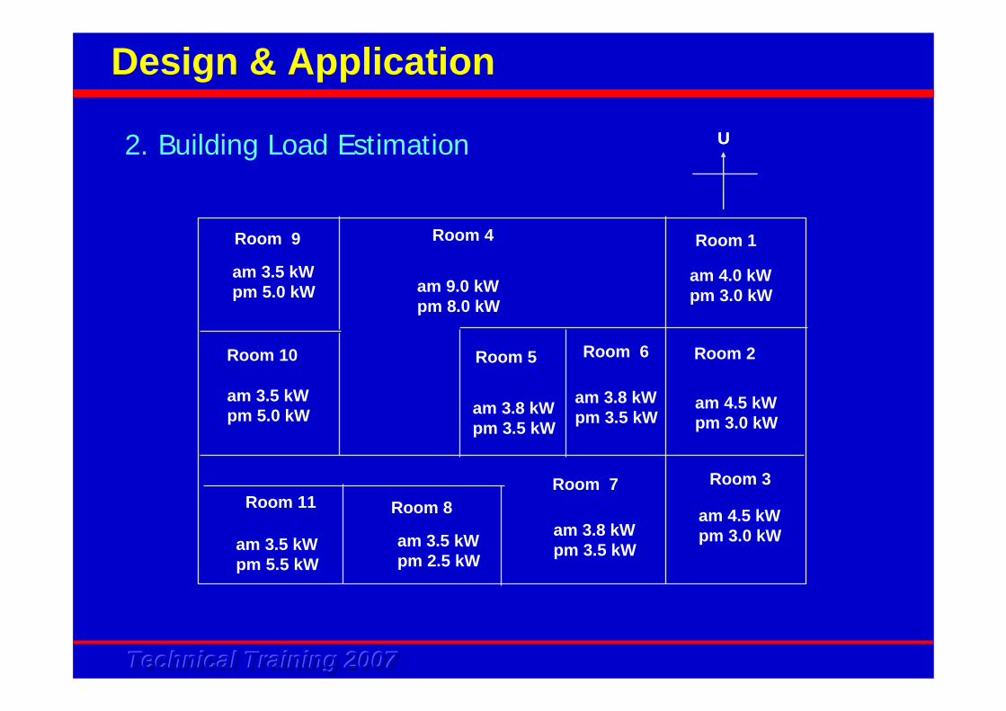
2. Building Load Estimation
Technical Training 2007Technical Training 2007Technical Training 2007
Design & Application
am 4.0 kWpm 3.0 kW
am 3.5 kWpm 5.0 kW
am 3.5 kWpm 5.5 kW
am 3.5 kWpm 2.5 kW
am 4.5 kWpm 3.0 kW
am 4.5 kWpm 3.0 kWam 3.8 kW
pm 3.5 kW
am 9.0 kWpm 8.0 kW
am 3.5 kWpm 5.0 kW
am 3.8 kWpm 3.5 kW
am 3.8 kWpm 3.5 kW
Room 9
Room 11
Room 10
Room 8 Room 7
Room 6Room 5
Room 4
Room 3
Room 2
Room 1
U U 2. Building Load Estimation
Technical Training 2007Technical Training 2007Technical Training 2007
Design & Application
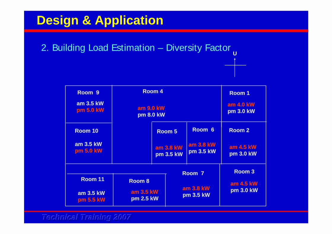
am 4.0 kWpm 3.0 kW
am 3.5 kWpm 5.0 kW
am 3.5 kWpm 5.5 kW
am 3.5 kWpm 2.5 kW
am 4.5 kWpm 3.0 kW
am 4.5 kWpm 3.0 kWam 3.8 kW
pm 3.5 kW
am 9.0 kWpm 8.0 kW
am 3.5 kWpm 5.0 kW
am 3.8 kWpm 3.5 kW
am 3.8 kWpm 3.5 kW
Room 9
Room 11
Room 10
Room 8 Room 7
Room 6Room 5
Room 4
Room 3
Room 2
Room 1
am 4.0 kWpm 3.0 kW
am 3.5 kWpm 5.0 kW
am 3.5 kWpm 5.5 kW
am 3.5 kWpm 2.5 kW
am 4.5 kWpm 3.0 kW
am 4.5 kWpm 3.0 kWam 3.8 kW
pm 3.5 kW
am 9.0 kWpm 8.0 kW
am 3.5 kWpm 5.0 kW
am 3.8 kWpm 3.5 kW
am 3.8 kWpm 3.5 kW
Room 9
Room 11
Room 10
Room 8 Room 7
Room 6Room 5
Room 4
Room 3
Room 2
Room 1
U 2. Building Load Estimation – Diversity Factor
Technical Training 2007Technical Training 2007Technical Training 2007
Design & Application
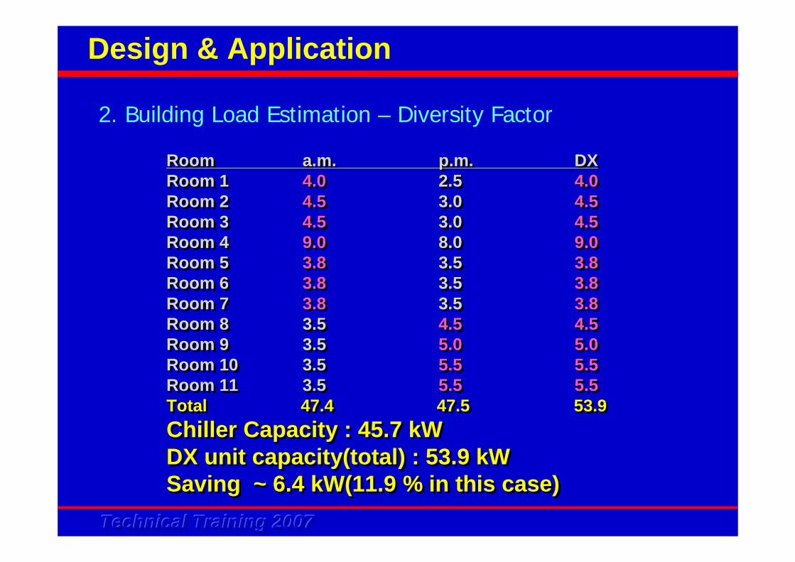
Room a.m. p.m. DXRoom 1 4.0 2.5 4.0Room 2 4.5 3.0 4.5Room 3 4.5 3.0 4.5Room 4 9.0 8.0 9.0Room 5 3.8 3.5 3.8Room 6 3.8 3.5 3.8Room 7 3.8 3.5 3.8Room 8 3.5 4.5 4.5Room 9 3.5 5.0 5.0Room 10 3.5 5.5 5.5Room 11 3.5 5.5 5.5Total 47.4 47.5 53.9Chiller Capacity : 45.7 kWDX unit capacity(total) : 53.9 kWSaving ~ 6.4 kW(11.9 % in this case)
Room a.m. p.m. DXRoom 1 4.0 2.5 4.0Room 2 4.5 3.0 4.5Room 3 4.5 3.0 4.5Room 4 9.0 8.0 9.0Room 5 3.8 3.5 3.8Room 6 3.8 3.5 3.8Room 7 3.8 3.5 3.8Room 8 3.5 4.5 4.5Room 9 3.5 5.0 5.0Room 10 3.5 5.5 5.5Room 11 3.5 5.5 5.5Total 47.4 47.5 53.9Chiller Capacity : 45.7 kWDX unit capacity(total) : 53.9 kWSaving ~ 6.4 kW(11.9 % in this case)
2. Building Load Estimation – Diversity Factor
Technical Training 2007Technical Training 2007Technical Training 2007
Criteria to select a mini chiller:• capacity required• water entering condition• water leaving condition• ambient condition• cooling/ heating mode required?
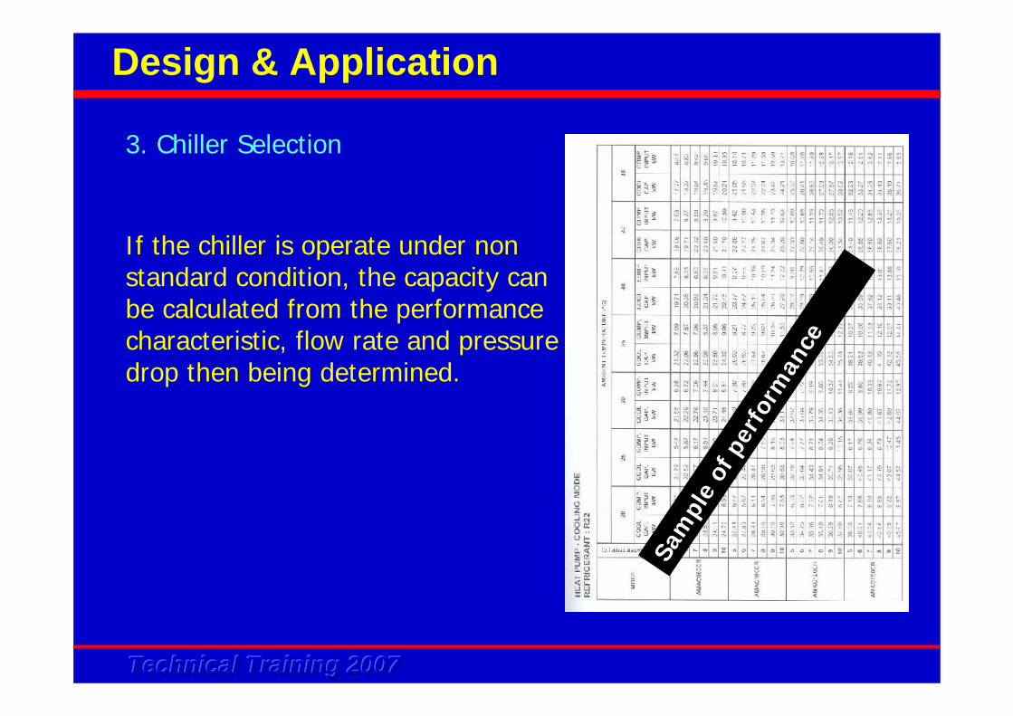
3. Chiller Selection
Design & Application
Technical Training 2007Technical Training 2007Technical Training 2007
If the chiller is operate under non standard condition, the capacity can be calculated from the performance characteristic, flow rate and pressure drop then being determined.
Sam
ple
of p
erfo
rman
ce c
hart
3. Chiller Selection
Design & Application
Technical Training 2007Technical Training 2007Technical Training 2007
Upon chiller units being selected, water flow rate of chiller and pressure drop also need to be determined.
Water flow rate, Liters/Min = Total Capacity, W
70 x Temp. Diff. O C
3. Chiller Selection
Design & Application
Technical Training 2007Technical Training 2007Technical Training 2007
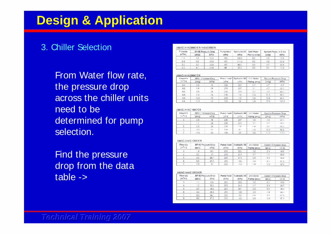
From Water flow rate, the pressure drop across the chiller units need to be determined for pump selection.
Find the pressure drop from the data table ->
3. Chiller Selection
Design & Application
Technical Training 2007Technical Training 2007Technical Training 2007
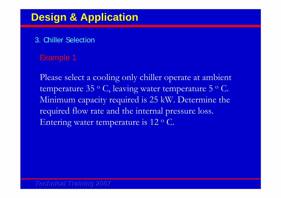
Example 1
Please select a cooling only chiller operate at ambient temperature 35 o C, leaving water temperature 5 o C. Minimum capacity required is 25 kW. Determine the required flow rate and the internal pressure loss.Entering water temperature is 12 o C.
3. Chiller Selection
Design & Application
Technical Training 2007Technical Training 2007Technical Training 2007
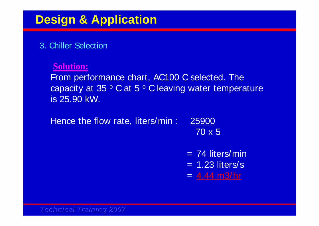
From performance chart, AC100 C selected. The capacity at 35 o C at 5 o C leaving water temperature is 25.90 kW.
Hence the flow rate, liters/min : 2590070 x 5
= 74 liters/min= 1.23 liters/s= 4.44 m3/hr
3. Chiller Selection
Design & Application
Solution:
Technical Training 2007Technical Training 2007Technical Training 2007
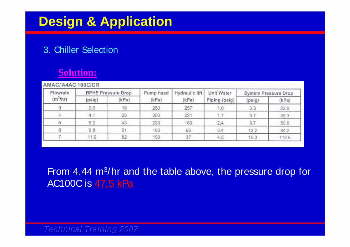
From 4.44 m3/hr and the table above, the pressure drop for AC100C is 47.5 kPa
3. Chiller Selection
Design & Application
Solution:
Technical Training 2007Technical Training 2007Technical Training 2007
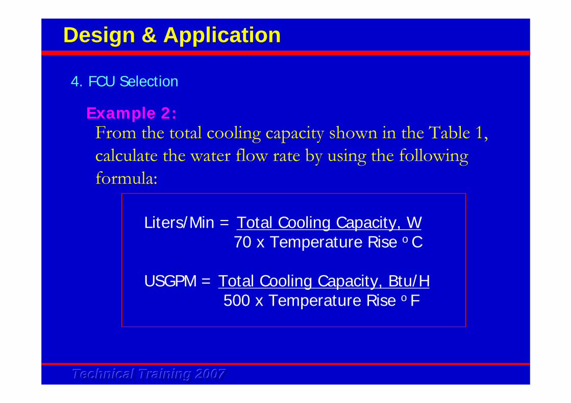
From the total cooling capacity shown in the Table 1, calculate the water flow rate by using the following formula:
Liters/Min = Total Cooling Capacity, W70 x Temperature Rise o C
USGPM = Total Cooling Capacity, Btu/H500 x Temperature Rise o F
4. FCU Selection
Design & Application
Example 2:
Technical Training 2007Technical Training 2007Technical Training 2007
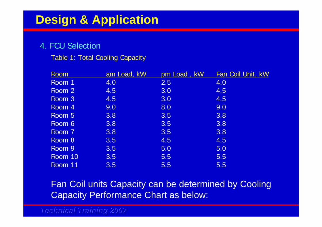
Table 1: Total Cooling Capacity
Room am Load, kW pm Load , kW Fan Coil Unit, kWRoom 1 4.0 2.5 4.0 Room 2 4.5 3.0 4.5Room 3 4.5 3.0 4.5Room 4 9.0 8.0 9.0Room 5 3.8 3.5 3.8Room 6 3.8 3.5 3.8Room 7 3.8 3.5 3.8Room 8 3.5 4.5 4.5Room 9 3.5 5.0 5.0Room 10 3.5 5.5 5.5Room 11 3.5 5.5 5.5
4. FCU Selection
Design & Application
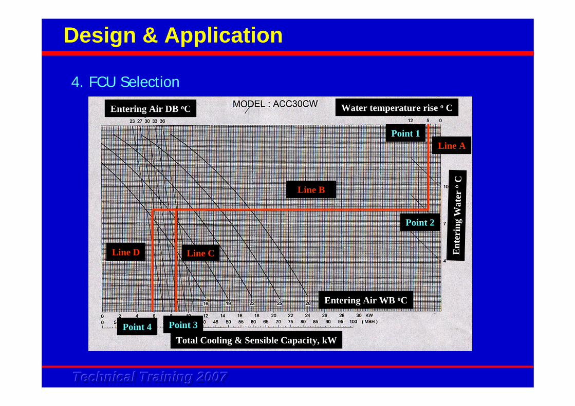
Fan Coil units Capacity can be determined by Cooling Capacity Performance Chart as below:
Technical Training 2007Technical Training 2007Technical Training 2007
Line A
Line D Line C
Line B
Point 1
Point 4 Point 3
Point 2
Water temperature rise o C
Ent
erin
g W
ater
oC
Total Cooling & Sensible Capacity, kW
Entering Air WB oC
Entering Air DB oC
4. FCU Selection
Design & Application
Technical Training 2007Technical Training 2007Technical Training 2007
Line A
Line D Line C
Line B
Point 1
Point 4 Point 3
Point 2
Water temperature rise o C
Ent
erin
g W
ater
oC
Total Cooling & Sensible Capacity, kW
Entering Air WB oC
Entering Air DB oC
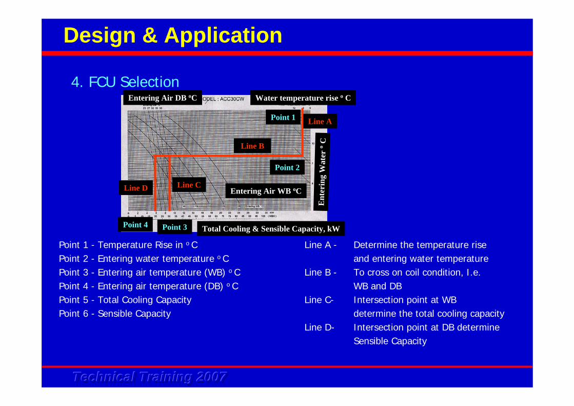
Point 1 - Temperature Rise in o C Line A - Determine the temperature risePoint 2 - Entering water temperature o C and entering water temperaturePoint 3 - Entering air temperature (WB) o C Line B - To cross on coil condition, I.e.Point 4 - Entering air temperature (DB) o C WB and DBPoint 5 - Total Cooling Capacity Line C- Intersection point at WB Point 6 - Sensible Capacity determine the total cooling capacity
Line D- Intersection point at DB determineSensible Capacity
4. FCU Selection
Design & Application
Technical Training 2007Technical Training 2007Technical Training 2007
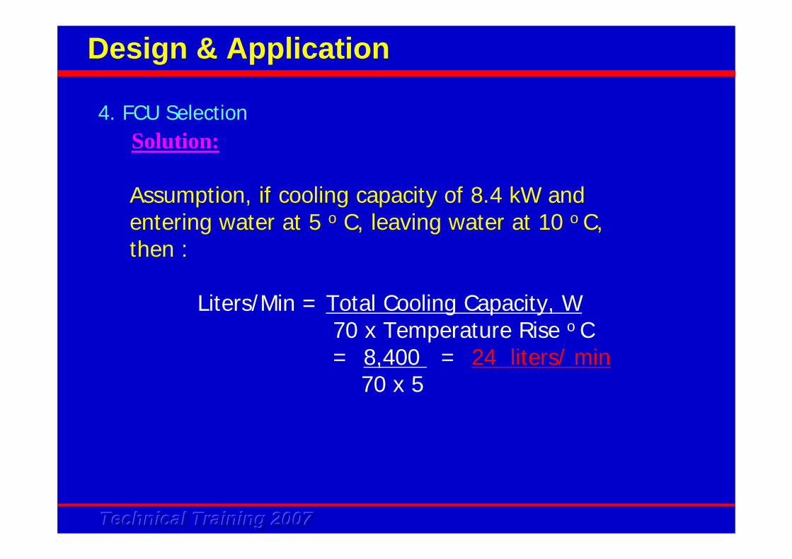
Assumption, if cooling capacity of 8.4 kW andentering water at 5 o C, leaving water at 10 o C,then :
Liters/Min = Total Cooling Capacity, W70 x Temperature Rise o C= 8,400 = 24 liters/ min
70 x 5
4. FCU Selection
Design & Application
Solution:
Technical Training 2007Technical Training 2007Technical Training 2007
4. FCU Selection
Design & Application
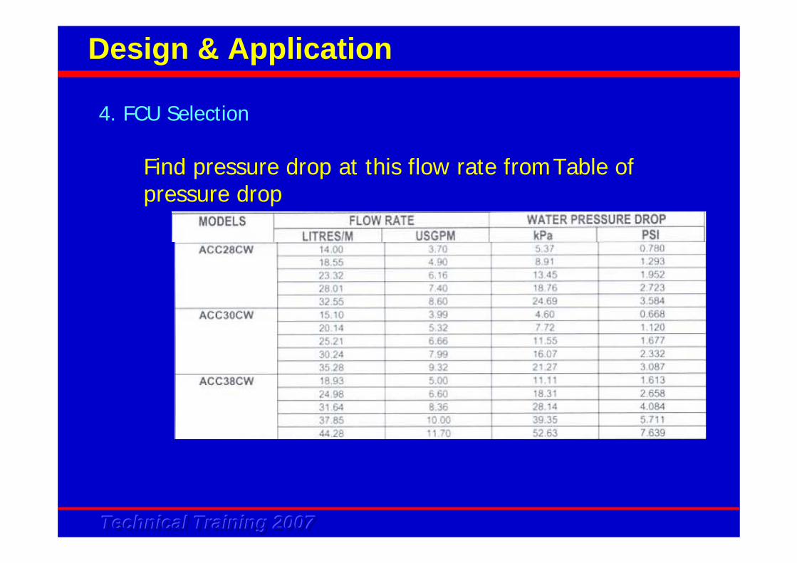
Find pressure drop at this flow rate fromTable of pressure drop
Technical Training 2007Technical Training 2007Technical Training 2007
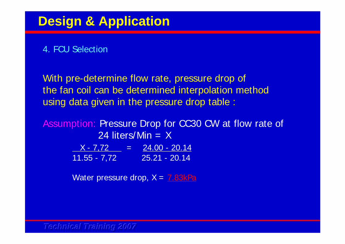
With pre-determine flow rate, pressure drop ofthe fan coil can be determined interpolation methodusing data given in the pressure drop table :
Assumption: Pressure Drop for CC30 CW at flow rate of24 liters/Min = X
X - 7,72 = 24.00 - 20.1411.55 - 7,72 25.21 - 20.14
Water pressure drop, X = 7.83kPa
4. FCU Selection
Design & Application
Technical Training 2007Technical Training 2007Technical Training 2007
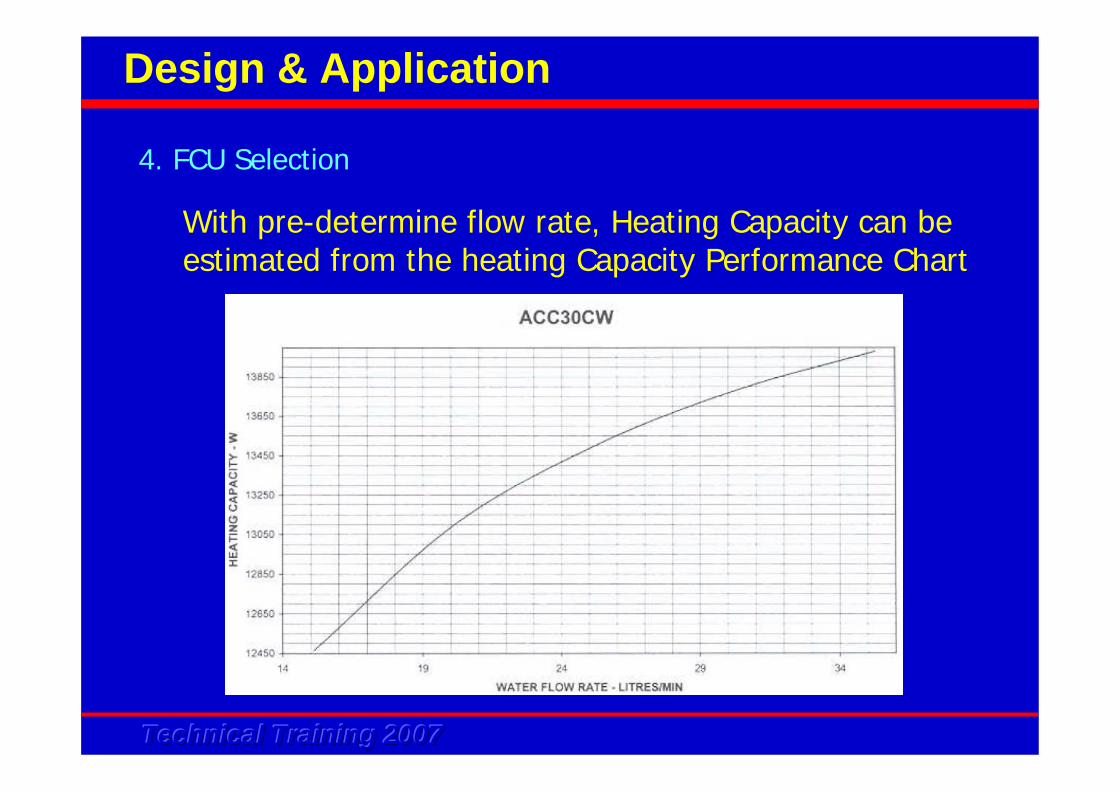
With pre-determine flow rate, Heating Capacity can be estimated from the heating Capacity Performance Chart
4. FCU Selection
Design & Application
Technical Training 2007Technical Training 2007Technical Training 2007
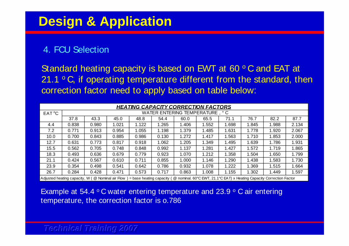
Standard heating capacity is based on EWT at 60 o C and EAT at 21.1 o C, if operating temperature different from the standard, then correction factor need to apply based on table below:
37.8 43.3 45.0 48.8 54.4 60.0 65.5 71.1 76.7 82.2 87.74.4 0.838 0.980 1.021 1.122 1.265 1.406 1.552 1.698 1.845 1.988 2.1347.2 0.771 0.913 0.954 1.055 1.198 1.379 1.485 1.631 1.778 1.920 2.067
10.0 0.700 0.843 0.885 0.986 0.130 1.272 1.417 1.563 1.710 1.853 2.00012.7 0.631 0.773 0.817 0.918 1.062 1.205 1.349 1.495 1.639 1.786 1.93115.5 0.562 0.705 0.748 0.848 0.992 1.137 1.281 1.427 1.572 1.719 1.86518.3 0.493 0.636 0.679 0.779 0.923 1.070 1.212 1.358 1.504 1.650 1.79921.1 0.424 0.567 0.610 0.711 0.855 1.000 1.146 1.290 1.438 1.583 1.73023.9 0.354 0.498 0.541 0.642 0.786 0.932 1.078 1.222 1.369 1.515 1.66426.7 0.284 0.428 0.471 0.573 0.717 0.863 1.008 1.155 1.302 1.449 1.597
WATER ENTERING TEMPERATURE , ° CHEATING CAPACITY CORRECTION FACTORS
EAT oC
Adjusted heating capacity, W ( @ Nominal air Flow ) = base heating capacity ( @ nominal. 60°C EWT, 21.1°C EAT) x Heating Capacity Correction Factor
Example at 54.4 o C water entering temperature and 23.9 o C air entering temperature, the correction factor is o.786
4. FCU Selection
Design & Application
Technical Training 2007Technical Training 2007Technical Training 2007
2 basic categories of water pipe work systems, i.e.
• Close System • Open System
5. Water Piping Design
Design & Application
Technical Training 2007Technical Training 2007Technical Training 2007
Close System
Pipe installation forms a close circuit minimum water loss in these type of system. Expansion tank / make up water tank is sufficient to top up the loss water
5. Water Piping Design
Design & Application
Technical Training 2007Technical Training 2007Technical Training 2007
• Mini chiller is designed with application of a close water piping system.
• Possible to use the unit with an open system by adding a buffer / intermediate tank and pump.
5. Water Piping Design
Design & Application
Technical Training 2007Technical Training 2007Technical Training 2007
Open System
Pipe works form an open loop. Usuallyuse for cooling tower, formation of alga / bacteria is normal. Water treatment required
5. Water Piping Design
Design & Application
Technical Training 2007Technical Training 2007Technical Training 2007
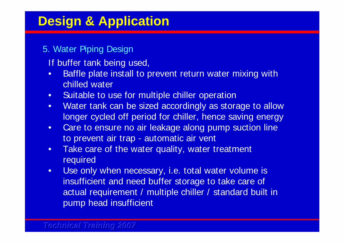
If buffer tank being used,• Baffle plate install to prevent return water mixing with
chilled water• Suitable to use for multiple chiller operation • Water tank can be sized accordingly as storage to allow
longer cycled off period for chiller, hence saving energy• Care to ensure no air leakage along pump suction line
to prevent air trap - automatic air vent• Take care of the water quality, water treatment
required• Use only when necessary, i.e. total water volume is
insufficient and need buffer storage to take care of actual requirement / multiple chiller / standard built in pump head insufficient
5. Water Piping Design
Design & Application
Technical Training 2007Technical Training 2007Technical Training 2007
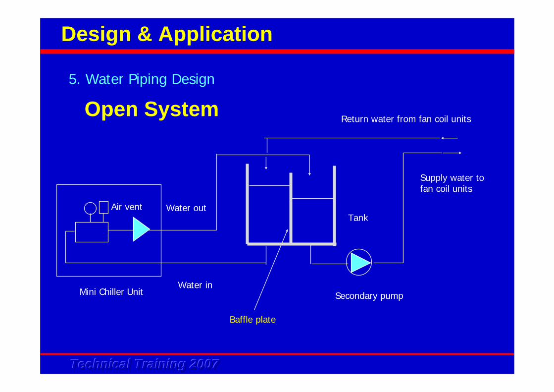
Open System5. Water Piping Design
Design & Application
Water out
Water inMini Chiller Unit
Return water from fan coil units
Supply water to fan coil units
Secondary pump
TankAir vent
Baffle plate
Technical Training 2007Technical Training 2007Technical Training 2007
Type of piping system
• Series• Diverting• Parallel direct return• Parallel reverse return
5. Water Piping Design
Design & Application
Technical Training 2007Technical Training 2007Technical Training 2007
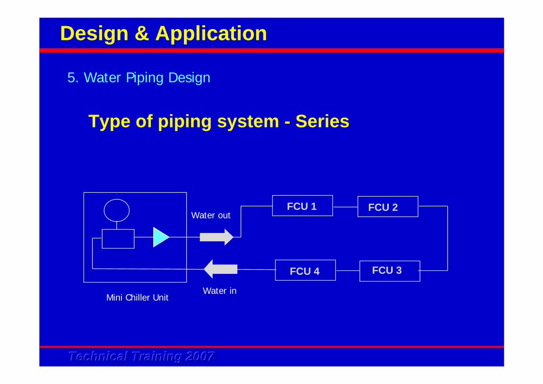
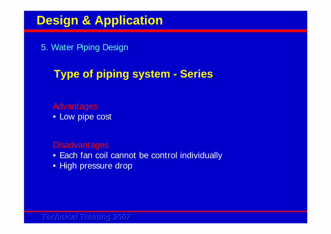
Type of piping system - Series
5. Water Piping Design
Design & Application
FCU 1 FCU 2
FCU 4 FCU 3
Water out
Water inMini Chiller Unit
Technical Training 2007Technical Training 2007Technical Training 2007
Advantages• Low pipe cost
5. Water Piping Design
Design & Application
Disadvantages• Each fan coil cannot be control individually• High pressure drop
Type of piping system - Series
Technical Training 2007Technical Training 2007Technical Training 2007
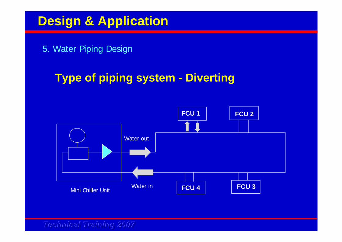
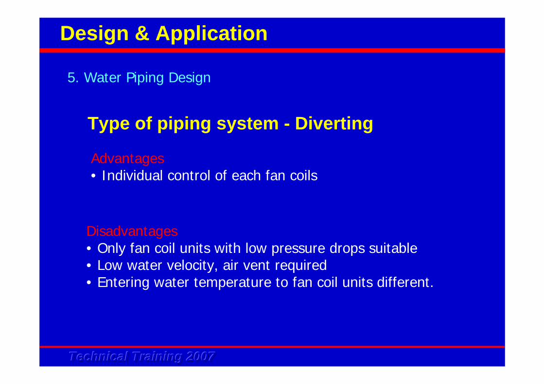
Type of piping system - Diverting
5. Water Piping Design
Design & Application
Mini Chiller Unit
Water out
Water in FCU 4 FCU 3
FCU 2FCU 1
Technical Training 2007Technical Training 2007Technical Training 2007
Advantages• Individual control of each fan coils
5. Water Piping Design
Design & Application
Disadvantages• Only fan coil units with low pressure drops suitable• Low water velocity, air vent required• Entering water temperature to fan coil units different.
Type of piping system - Diverting
Technical Training 2007Technical Training 2007Technical Training 2007
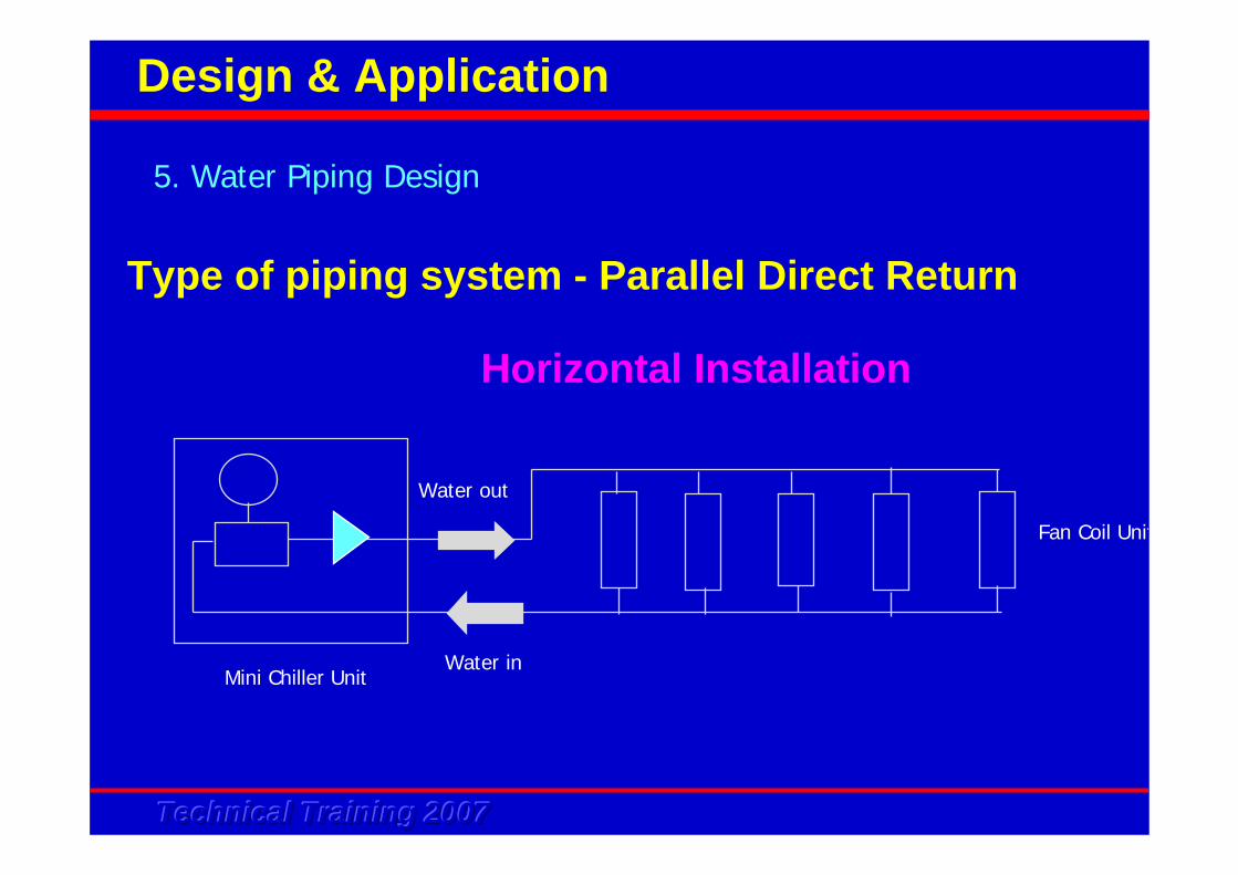
Horizontal Installation
Type of piping system - Parallel Direct Return
5. Water Piping Design
Design & Application
Mini Chiller Unit
Water out
Water in
Fan Coil Unit
Technical Training 2007Technical Training 2007Technical Training 2007
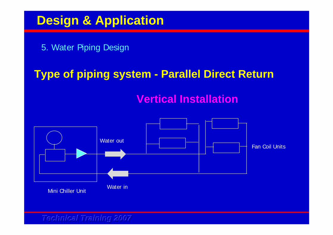
5. Water Piping Design
Design & Application
Type of piping system - Parallel Direct Return
Mini Chiller Unit
Water out
Water in
Fan Coil Units
Vertical Installation

Technical Training 2007Technical Training 2007Technical Training 2007
• 1st in 1st out• Supply and return pipe length uneven • Proper balancing of water flow required• More economical compare to reverse return type
5. Water Piping Design
Design & Application
Type of piping system - Parallel Direct Return
Technical Training 2007Technical Training 2007Technical Training 2007
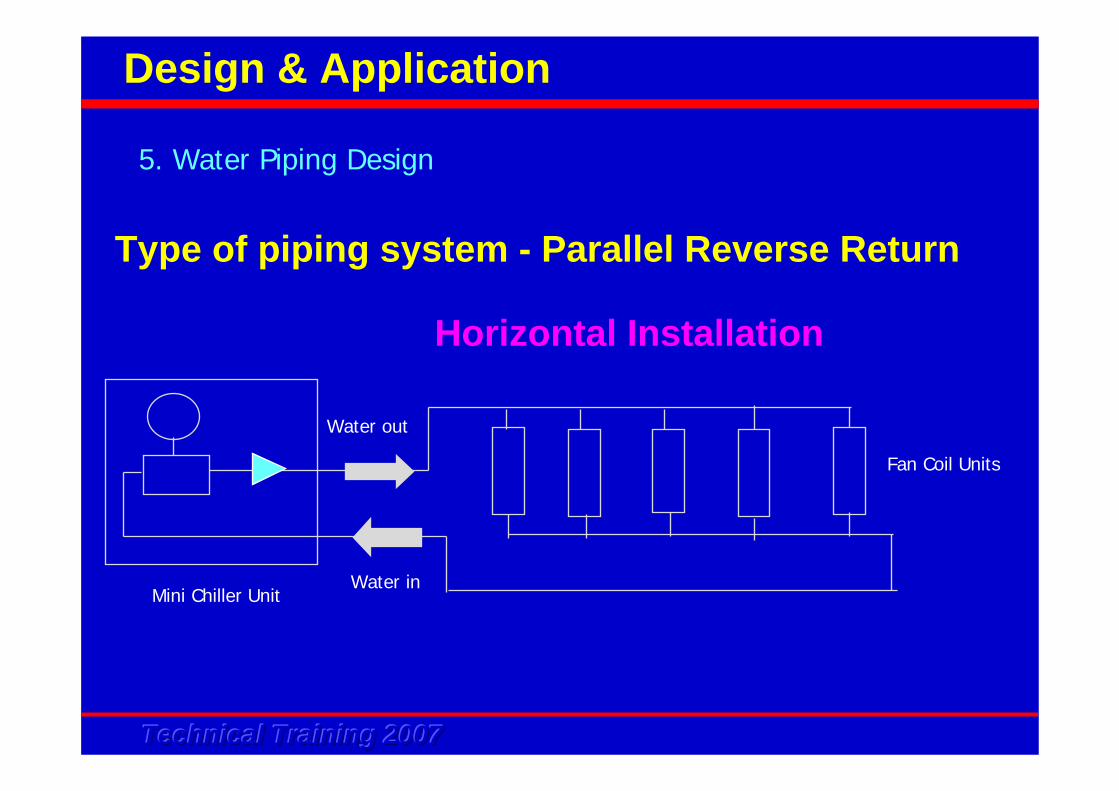
Horizontal Installation
Type of piping system - Parallel Reverse Return
5. Water Piping Design
Design & Application
Mini Chiller Unit
Water out
Water in
Fan Coil Units
Technical Training 2007Technical Training 2007Technical Training 2007
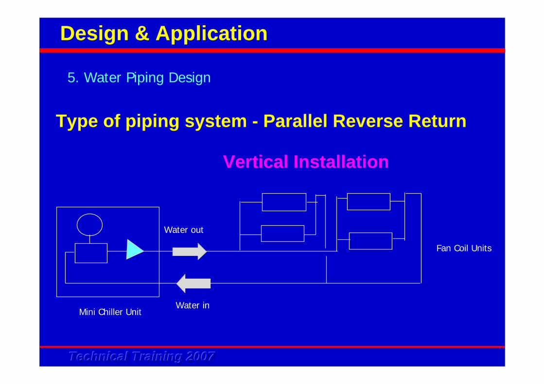
5. Water Piping Design
Design & Application
Type of piping system - Parallel Reverse Return
Vertical Installation
Mini Chiller Unit
Water out
Water in
Fan Coil Units
Technical Training 2007Technical Training 2007Technical Training 2007
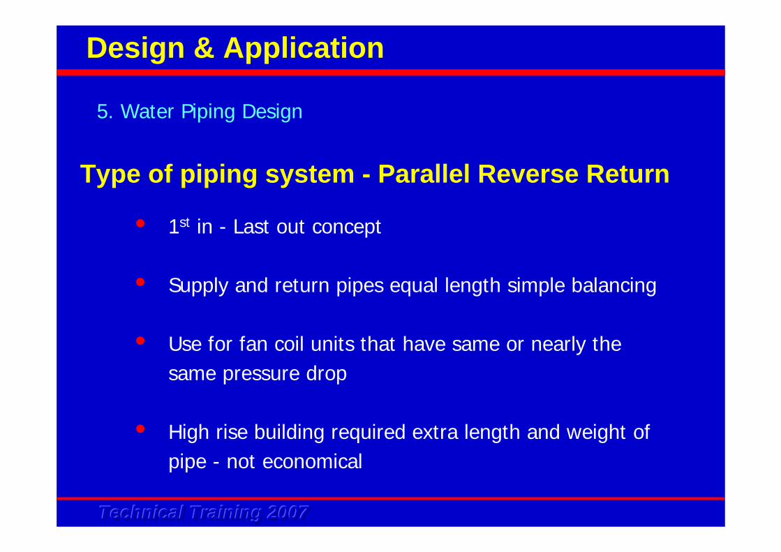
• 1st in - Last out concept
• Supply and return pipes equal length simple balancing
• Use for fan coil units that have same or nearly the same pressure drop
• High rise building required extra length and weight of pipe - not economical
5. Water Piping Design
Design & Application
Type of piping system - Parallel Reverse Return
Technical Training 2007Technical Training 2007Technical Training 2007
Type of pipes and fittings
There are several types of pipe that normally use in for water piping
• Black carbon steel pipe• Copper pipe• PVC pipe
5. Water Piping Design
Design & Application
Technical Training 2007Technical Training 2007Technical Training 2007
Black carbon steel pipe
• Joint by arc welding; thread; flange with gasket
• Most commonly used in chiller installation
5. Water Piping Design
Design & Application
Type of pipes and fittings
Technical Training 2007Technical Training 2007Technical Training 2007
Copper pipe
• High resistance to corrosion and ease installation
• High cost
• Can be joint by brazing; soldering; flare joint
5. Water Piping Design
Design & Application
Type of pipes and fittings
Technical Training 2007Technical Training 2007Technical Training 2007
PVC pipes
• Light weight
• Corrosion resistance
• Not suitable for high temperature application
• Installed with more support(shorter span)
• UPVC generally up to 60 oC usage
• CPVC higher temperature application
• Method to joint : solvent cementing / welding; thread
5. Water Piping Design
Design & Application
Type of pipes and fittings
Technical Training 2007Technical Training 2007Technical Training 2007
Galvanized iron(GI) is not recommended as Zinc coating on the GI pipe will have an electrolytic reaction with the copper components in the system, i.e. BPHE; fan coil heat exchanger. The zinc will be sacrificial metal and deposit itselfon the copper surface
• Zinc surface slowly eroded• Zinc deposit on the copper surface will retard heat transfer
process
5. Water Piping Design
Design & Application
Type of pipes and fittings
Technical Training 2007Technical Training 2007Technical Training 2007
Fitting for steel pipe, treaded
• 90 o elbow• tee joint• reducer• connector• union• nipple• flange
5. Water Piping Design
Design & Application
Type of pipes and fittings
Technical Training 2007Technical Training 2007Technical Training 2007
Fitting for Copper pipes - expanded end for brazing or
threaded end
• 90 o elbow
• Reducer
• Tee joint
• Connector
5. Water Piping Design
Design & Application
Type of pipes and fittings
Technical Training 2007Technical Training 2007Technical Training 2007
Fitting for PVC pipes (with treaded end-can joint to steel pipe of fitting
• 90 o elbow• Tee joint• Connector• Adapter• Socket• Union• Reducer
5. Water Piping Design
Design & Application
Type of pipes and fittings
Technical Training 2007Technical Training 2007Technical Training 2007
Type of pipes and valvesValves
- One of the important component in a water piping
system with the following functions:
• To isolate a component from the system - enable
easy servicing/maintenance
• To regulate water flow rate
• To divert / mix flow direction
• To prevent back flow
• To relieve / regulate pressure
5. Water Piping Design
Design & Application
Technical Training 2007Technical Training 2007Technical Training 2007
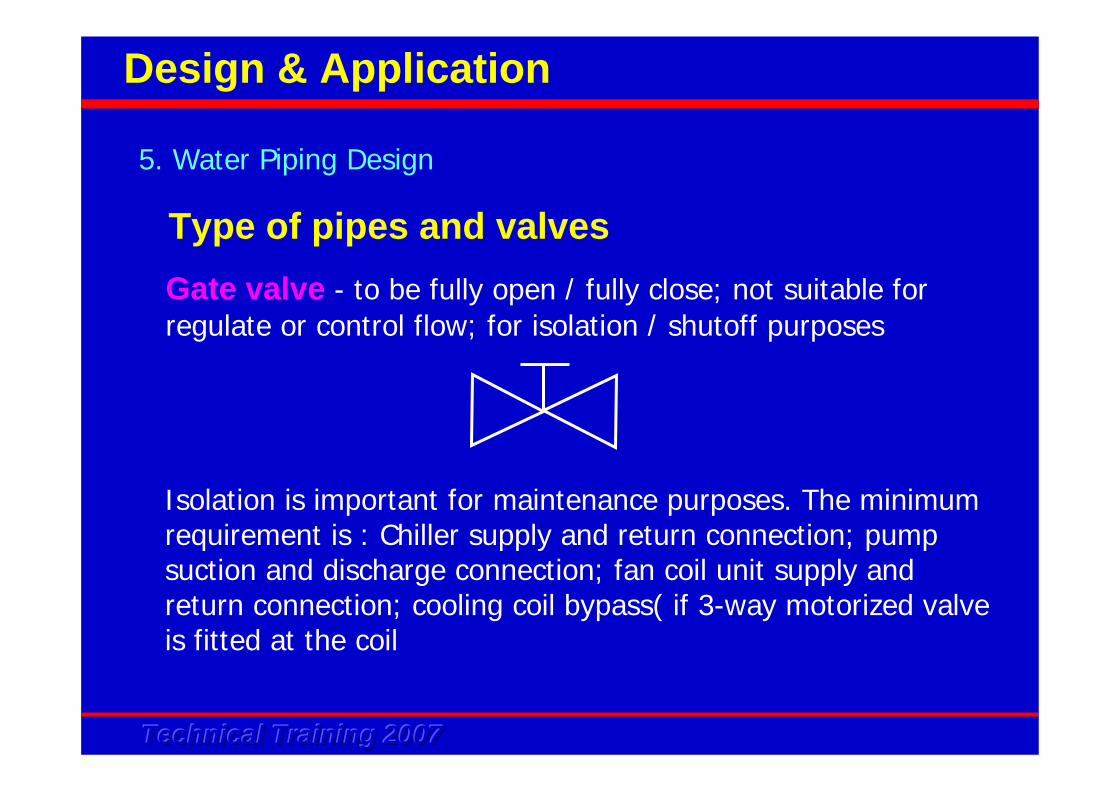
Gate valve - to be fully open / fully close; not suitable for regulate or control flow; for isolation / shutoff purposes
Isolation is important for maintenance purposes. The minimum requirement is : Chiller supply and return connection; pump suction and discharge connection; fan coil unit supply and return connection; cooling coil bypass( if 3-way motorized valve is fitted at the coil
5. Water Piping Design
Design & Application
Type of pipes and valves
Technical Training 2007Technical Training 2007Technical Training 2007
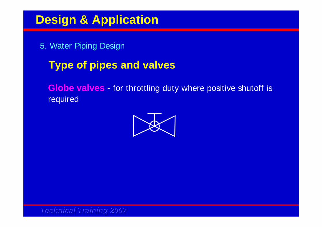
Globe valves - for throttling duty where positive shutoff is required
5. Water Piping Design
Design & Application
Type of pipes and valves
Technical Training 2007Technical Training 2007Technical Training 2007
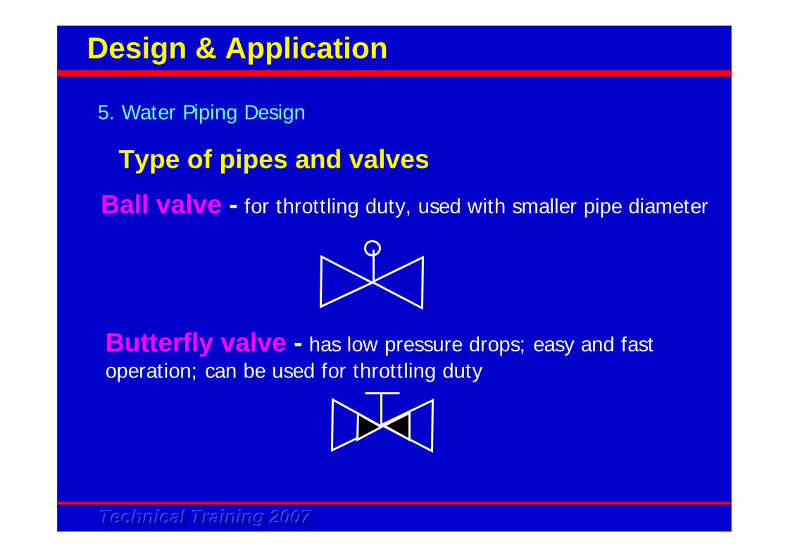
Ball valve - for throttling duty, used with smaller pipe diameter
Butterfly valve - has low pressure drops; easy and fast operation; can be used for throttling duty
5. Water Piping Design
Design & Application
Type of pipes and valves
Technical Training 2007Technical Training 2007Technical Training 2007
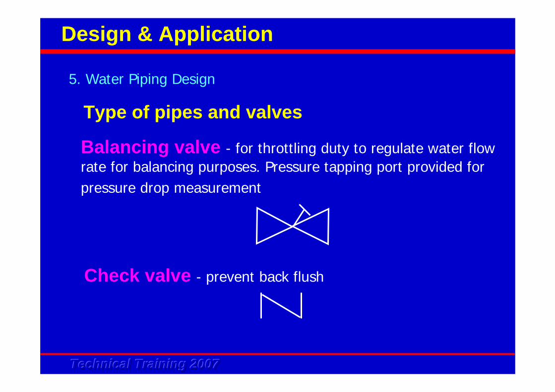
Balancing valve - for throttling duty to regulate water flow rate for balancing purposes. Pressure tapping port provided for pressure drop measurement
Check valve - prevent back flush
5. Water Piping Design
Design & Application
Type of pipes and valves
Technical Training 2007Technical Training 2007Technical Training 2007
Actuators- Automatic valves operate for automatic controller to
control the fluid flow. Common actuators are :
• Solenoid valve
• electric motorized valve
• pneumatic valve
5. Water Piping Design
Design & Application
Type of pipes and valves
Technical Training 2007Technical Training 2007Technical Training 2007
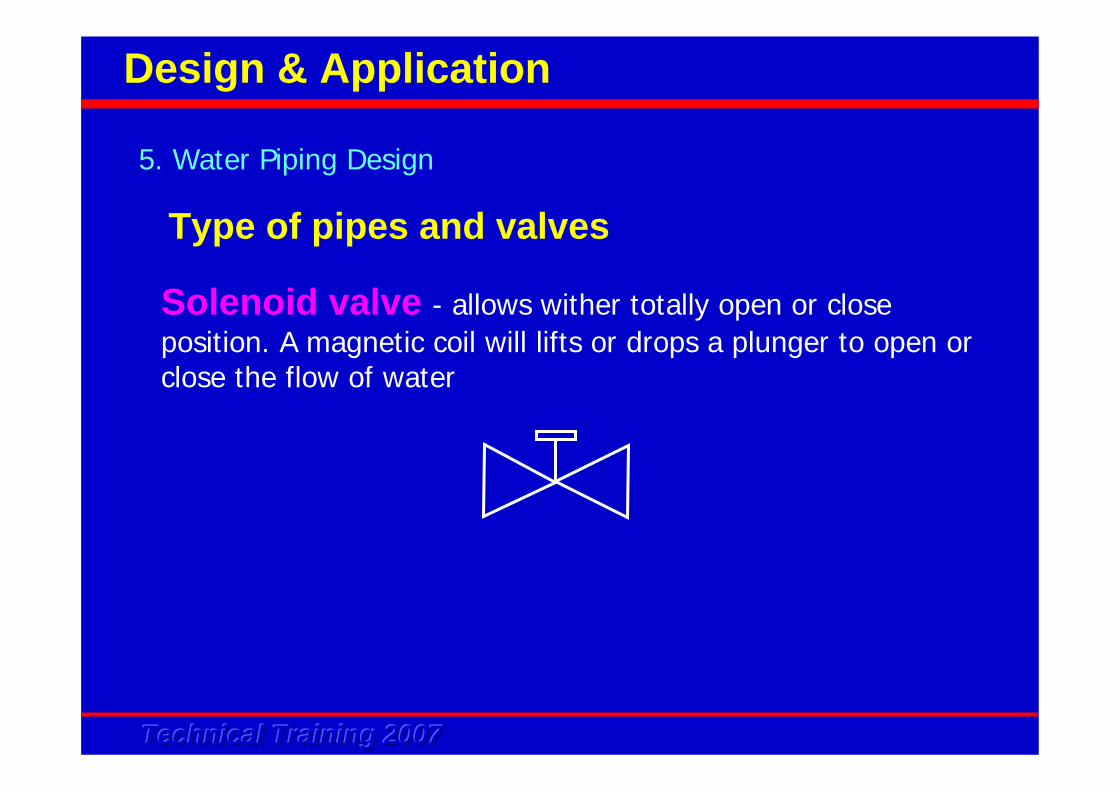
Solenoid valve - allows wither totally open or close position. A magnetic coil will lifts or drops a plunger to open or close the flow of water
5. Water Piping Design
Design & Application
Type of pipes and valves
Technical Training 2007Technical Training 2007Technical Training 2007
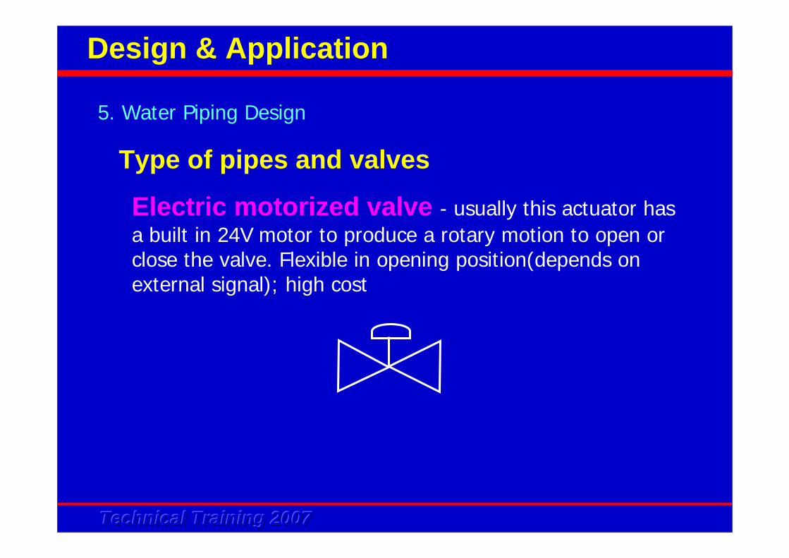
Electric motorized valve - usually this actuator has a built in 24V motor to produce a rotary motion to open or close the valve. Flexible in opening position(depends on external signal); high cost
5. Water Piping Design
Design & Application
Type of pipes and valves
Technical Training 2007Technical Training 2007Technical Training 2007
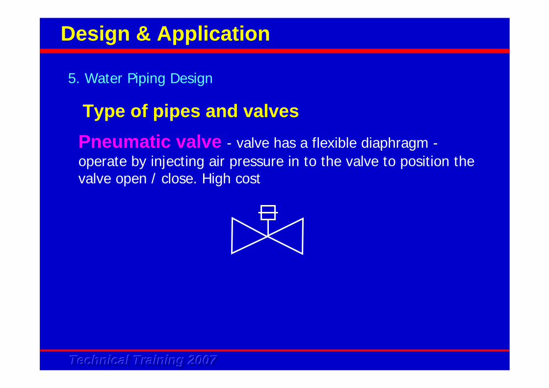
Pneumatic valve - valve has a flexible diaphragm -operate by injecting air pressure in to the valve to position the valve open / close. High cost
5. Water Piping Design
Design & Application
Type of pipes and valves
Technical Training 2007Technical Training 2007Technical Training 2007
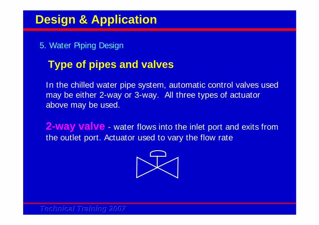
In the chilled water pipe system, automatic control valves used may be either 2-way or 3-way. All three types of actuator above may be used.
2-way valve - water flows into the inlet port and exits from the outlet port. Actuator used to vary the flow rate
5. Water Piping Design
Design & Application
Type of pipes and valves
Technical Training 2007Technical Training 2007Technical Training 2007
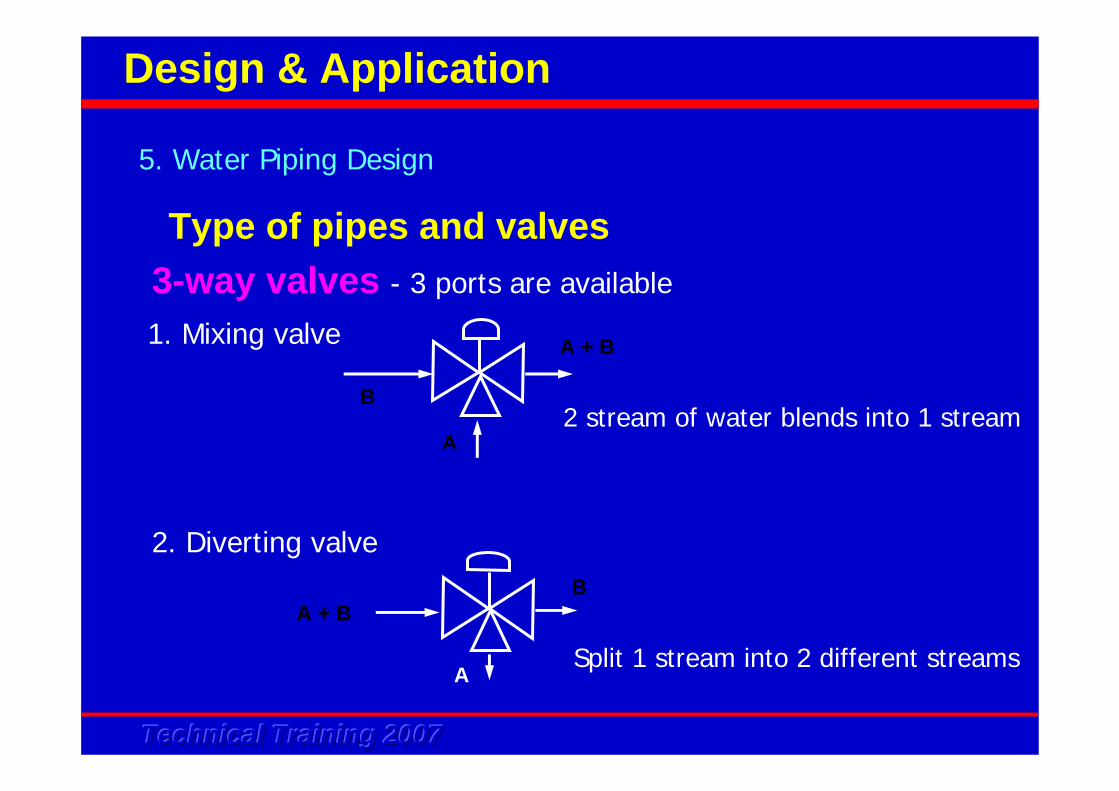
3-way valves - 3 ports are available
1. Mixing valve
B
A
A + B
2 stream of water blends into 1 stream
2. Diverting valve
A + B
A
B
Split 1 stream into 2 different streams
5. Water Piping Design
Design & Application
Type of pipes and valves
Technical Training 2007Technical Training 2007Technical Training 2007
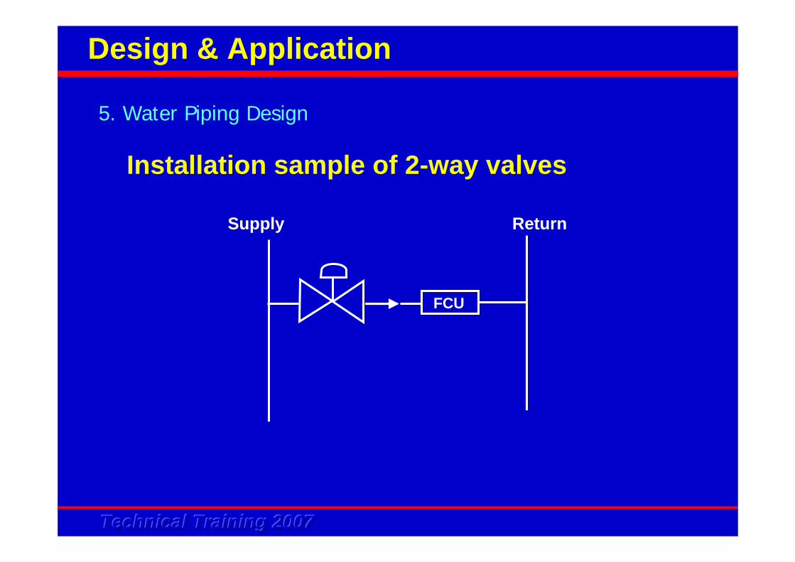
Installation sample of 2-way valves
FCU
Supply Return
5. Water Piping Design
Design & Application
Technical Training 2007Technical Training 2007Technical Training 2007
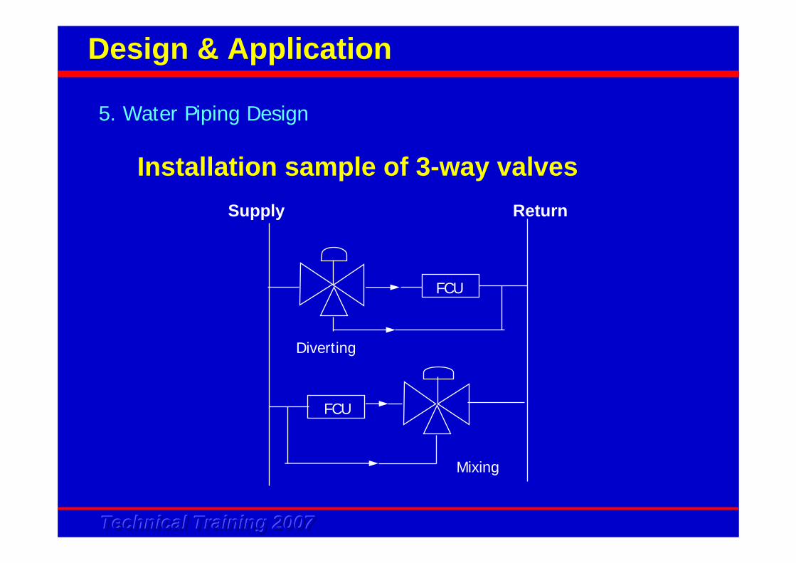
Installation sample of 3-way valves
FCU
FCU
Supply Return
Diverting
Mixing
5. Water Piping Design
Design & Application
Technical Training 2007Technical Training 2007Technical Training 2007
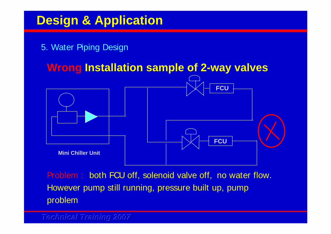
Wrong Installation sample of 2-way valves
5. Water Piping Design
Design & Application
FCU
Mini Chiller Unit
FCU
Problem : both FCU off, solenoid valve off, no water flow. However pump still running, pressure built up, pump problem
Technical Training 2007Technical Training 2007Technical Training 2007
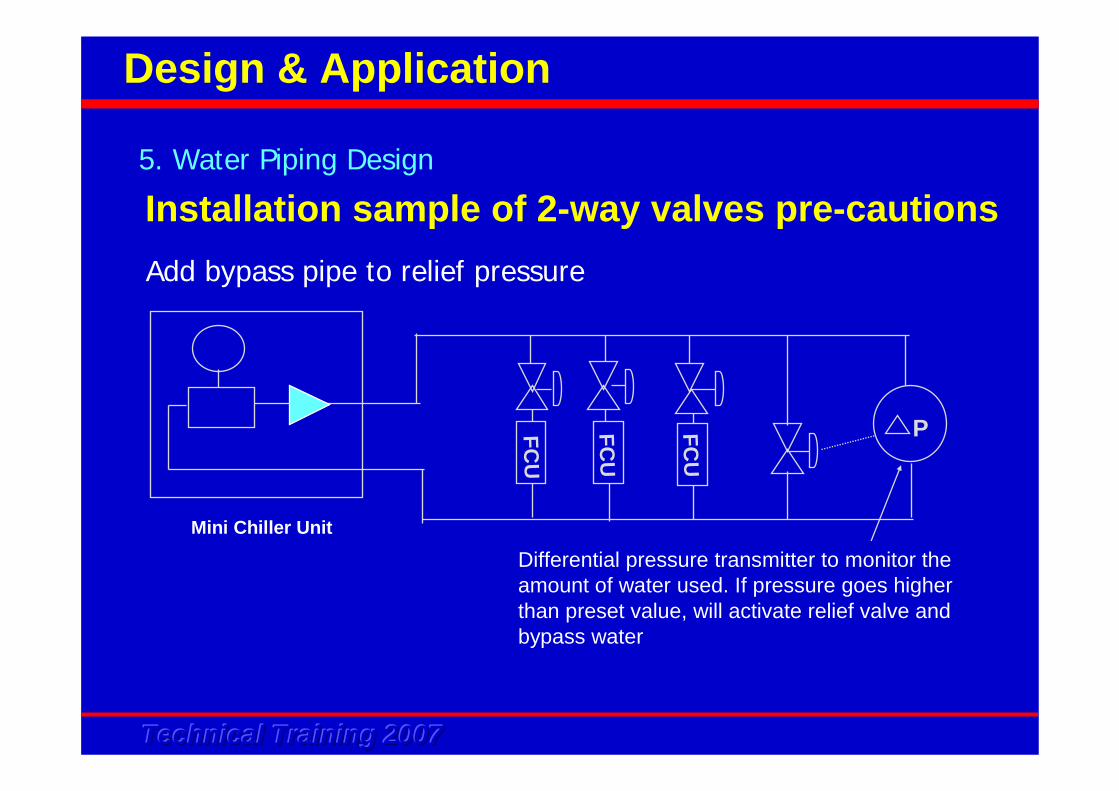
Add bypass pipe to relief pressure
5. Water Piping Design
Design & Application
Mini Chiller Unit
FCU
FCU
FCU
P
Differential pressure transmitter to monitor theamount of water used. If pressure goes higher than preset value, will activate relief valve and bypass water
Installation sample of 2-way valves pre-cautions
Technical Training 2007Technical Training 2007Technical Training 2007
5. Water Piping Design
Design & Application
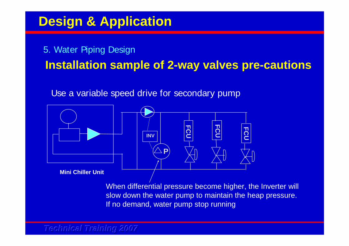
Installation sample of 2-way valves pre-cautions
Mini Chiller Unit
FCU
FCU
FCU
P
INV
When differential pressure become higher, the Inverter willslow down the water pump to maintain the heap pressure.If no demand, water pump stop running
Use a variable speed drive for secondary pump
Technical Training 2007Technical Training 2007Technical Training 2007
Modify control wiring for chiller and fan coil unit
The above method of 2-way valves installation incur high cost due to extra piping, fittings, pressure transmitter...... There is possible to change the control wiring of the system. Normally when the fan coil unit thermostat cut-off, the power supply to control the 2-way valve will be off. It is possible to run a line from the thermostat to the chiller remote switch whereby when the thermostat cut-off, the chiller and pump will also cut-off.
5. Water Piping Design
Design & Application
Installation sample of 2-way valves pre-cautions
Technical Training 2007Technical Training 2007Technical Training 2007
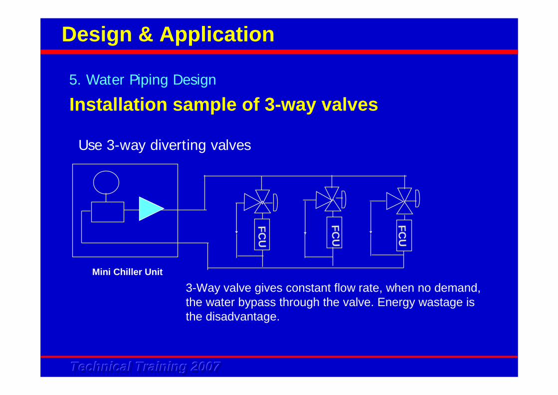
Installation sample of 3-way valves5. Water Piping Design
Design & Application
Mini Chiller Unit
FCU
FCU
FCU
3-Way valve gives constant flow rate, when no demand,the water bypass through the valve. Energy wastage is the disadvantage.
Use 3-way diverting valves
Technical Training 2007Technical Training 2007Technical Training 2007
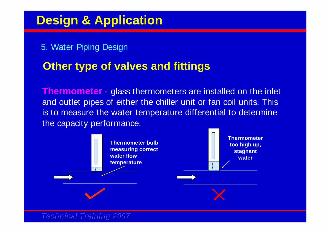
Other type of valves and fittings
Thermometer - glass thermometers are installed on the inlet and outlet pipes of either the chiller unit or fan coil units. This is to measure the water temperature differential to determine the capacity performance.
Thermometer bulb measuring correct water flow temperature
Thermometer too high up,
stagnant water
5. Water Piping Design
Design & Application
Technical Training 2007Technical Training 2007Technical Training 2007
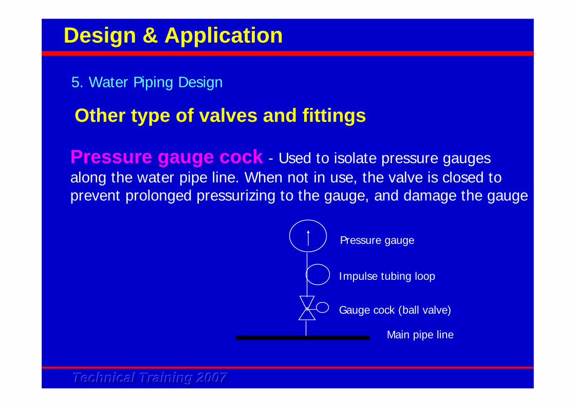
Pressure gauge cock - Used to isolate pressure gauges along the water pipe line. When not in use, the valve is closed to prevent prolonged pressurizing to the gauge, and damage the gauge
Pressure gauge
Impulse tubing loop
Gauge cock (ball valve)
Main pipe line
5. Water Piping Design
Design & Application
Other type of valves and fittings
Technical Training 2007Technical Training 2007Technical Training 2007
Pressure gauge and thermometer as the previous 2 slides should be included in the design stage - consideration for commissioning. The measuring devices should be installed at the following location :
• Main supply and return pipe • Main branch supply/return pipe• Cooling coils• Heating coils• Chiller (chilled water side)
5. Water Piping Design
Design & Application
Other type of valves and fittings
Technical Training 2007Technical Training 2007Technical Training 2007
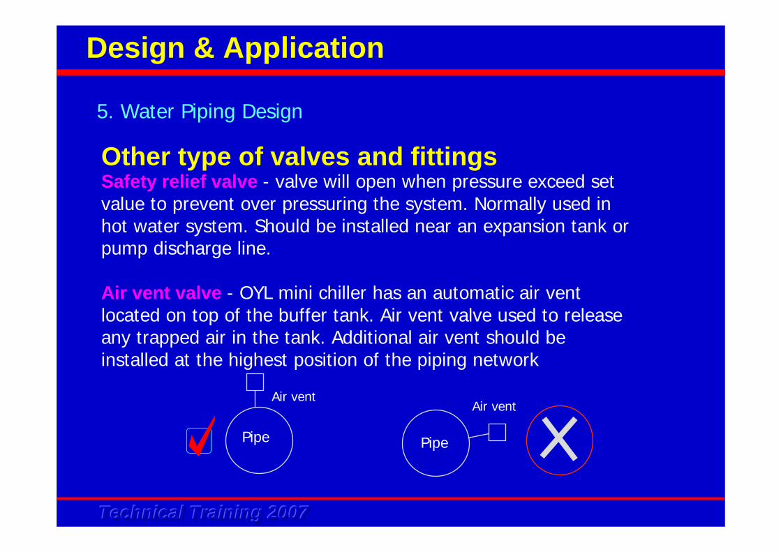
Safety relief valve - valve will open when pressure exceed set value to prevent over pressuring the system. Normally used in hot water system. Should be installed near an expansion tank or pump discharge line.
Air vent valve - OYL mini chiller has an automatic air vent located on top of the buffer tank. Air vent valve used to release any trapped air in the tank. Additional air vent should be installed at the highest position of the piping network
5. Water Piping Design
Design & Application
Other type of valves and fittings
Pipe Pipe
Air ventAir vent
Technical Training 2007Technical Training 2007Technical Training 2007
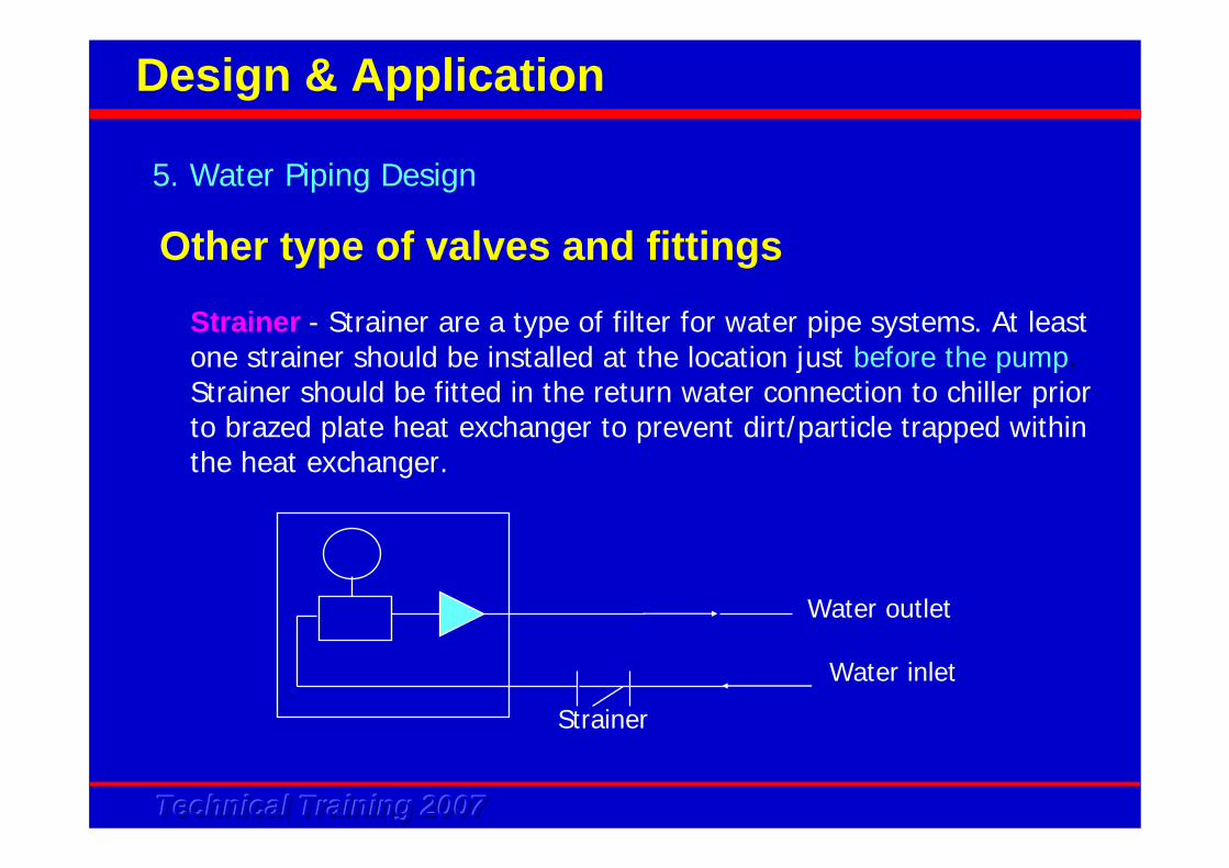
Water outlet
Water inlet
Strainer
Strainer - Strainer are a type of filter for water pipe systems. At least one strainer should be installed at the location just before the pump. Strainer should be fitted in the return water connection to chiller prior to brazed plate heat exchanger to prevent dirt/particle trapped within the heat exchanger.
5. Water Piping Design
Design & Application
Other type of valves and fittings
Technical Training 2007Technical Training 2007Technical Training 2007
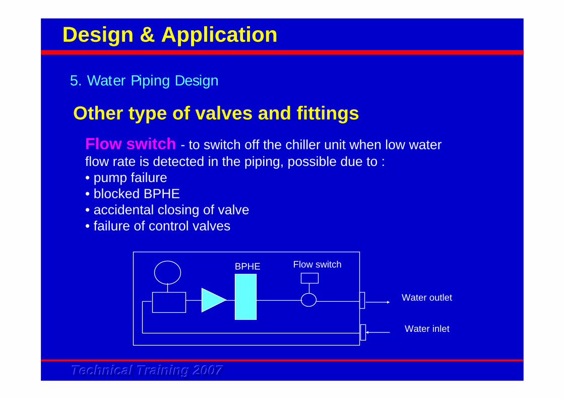
Flow switch - to switch off the chiller unit when low water flow rate is detected in the piping, possible due to :• pump failure• blocked BPHE• accidental closing of valve• failure of control valves
Water outlet
Water inlet
BPHE Flow switch
5. Water Piping Design
Design & Application
Other type of valves and fittings
Technical Training 2007Technical Training 2007Technical Training 2007
• Fan coil pressure loss
• Chiller pressure loss
• Pipe pressure loss - pipe, fittings & component
5. Water Piping Design
Design & Application
System Pressure Loss
Technical Training 2007Technical Training 2007Technical Training 2007
Pipe friction looses are dependent on the following factors :
• Water velocity• Pipe internal diameter• Pipe length• Type of material - affect the internal wall roughness
5. Water Piping Design
Design & Application
Pipe and Fitting Sizing
Technical Training 2007Technical Training 2007Technical Training 2007
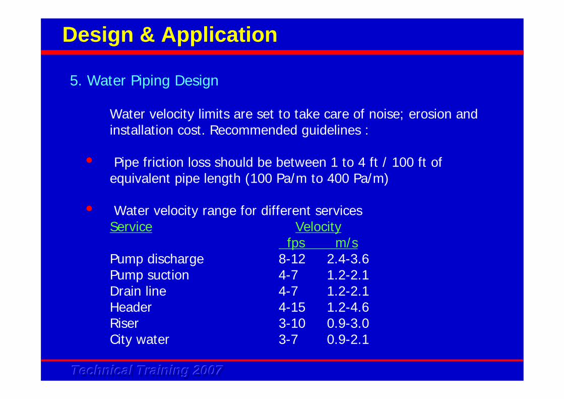
Water velocity limits are set to take care of noise; erosion andinstallation cost. Recommended guidelines :
• Pipe friction loss should be between 1 to 4 ft / 100 ft of equivalent pipe length (100 Pa/m to 400 Pa/m)
• Water velocity range for different servicesService Velocity
fps m/sPump discharge 8-12 2.4-3.6Pump suction 4-7 1.2-2.1Drain line 4-7 1.2-2.1Header 4-15 1.2-4.6Riser 3-10 0.9-3.0City water 3-7 0.9-2.1
5. Water Piping Design
Design & Application
Technical Training 2007Technical Training 2007Technical Training 2007
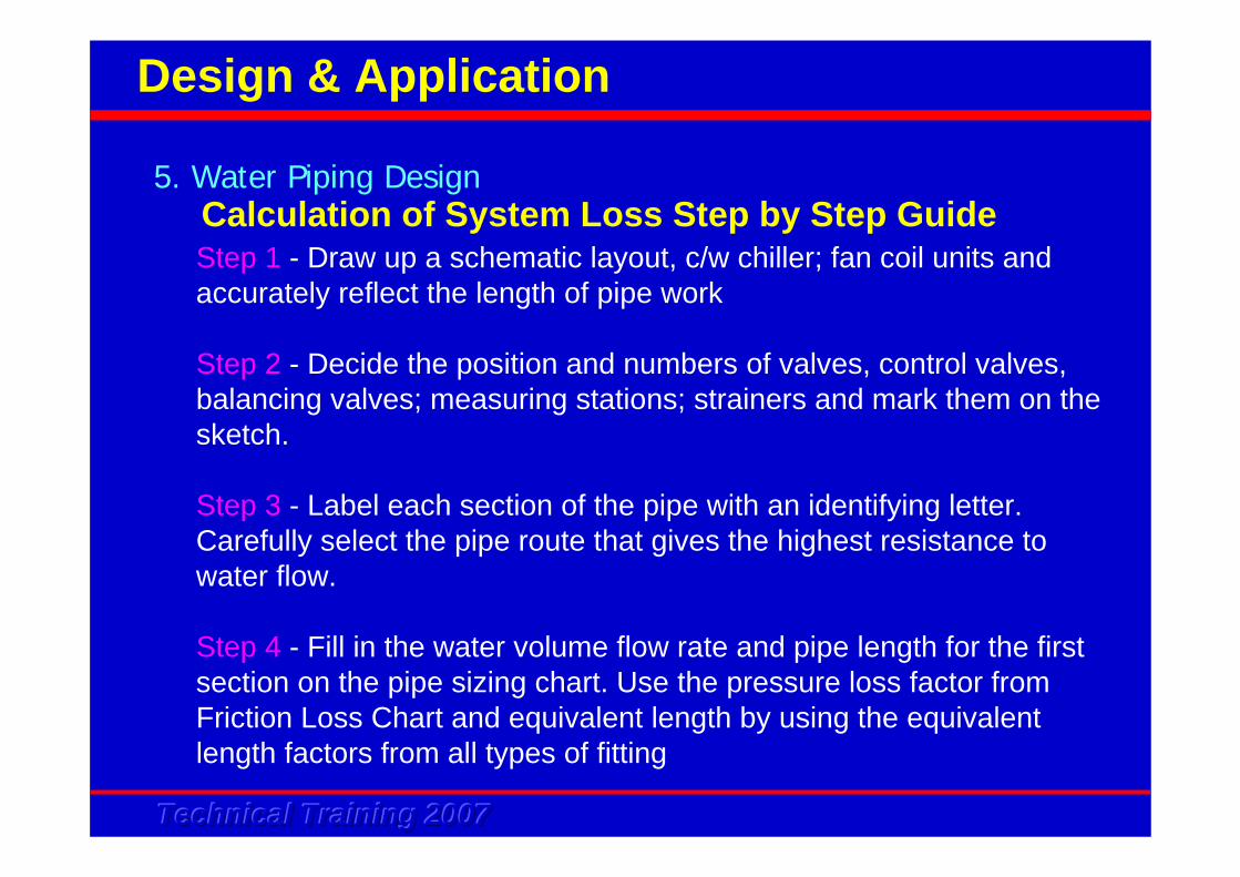
Calculation of System Loss Step by Step GuideStep 1 - Draw up a schematic layout, c/w chiller; fan coil units and accurately reflect the length of pipe work
Step 2 - Decide the position and numbers of valves, control valves, balancing valves; measuring stations; strainers and mark them on the sketch.
Step 3 - Label each section of the pipe with an identifying letter. Carefully select the pipe route that gives the highest resistance to water flow.
Step 4 - Fill in the water volume flow rate and pipe length for the first section on the pipe sizing chart. Use the pressure loss factor from Friction Loss Chart and equivalent length by using the equivalent length factors from all types of fitting
5. Water Piping Design
Design & Application
Technical Training 2007Technical Training 2007Technical Training 2007
Calculation of System Loss Step by Step Guide
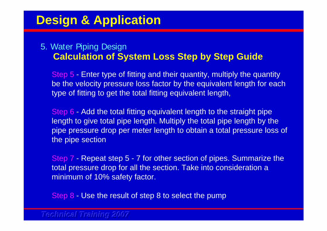
Step 5 - Enter type of fitting and their quantity, multiply the quantitybe the velocity pressure loss factor by the equivalent length for each type of fitting to get the total fitting equivalent length,
Step 6 - Add the total fitting equivalent length to the straight pipe length to give total pipe length. Multiply the total pipe length by the pipe pressure drop per meter length to obtain a total pressure loss of the pipe section
Step 7 - Repeat step 5 - 7 for other section of pipes. Summarize the total pressure drop for all the section. Take into consideration a minimum of 10% safety factor.
Step 8 - Use the result of step 8 to select the pump
5. Water Piping Design
Design & Application
Technical Training 2007Technical Training 2007Technical Training 2007
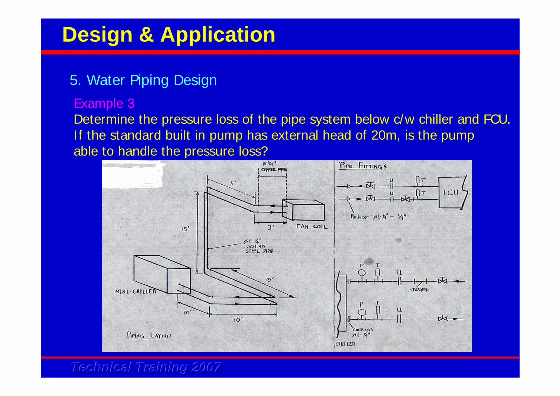
Example 3 Determine the pressure loss of the pipe system below c/w chiller and FCU. If the standard built in pump has external head of 20m, is the pump able to handle the pressure loss?
5. Water Piping Design
Design & Application
Technical Training 2007Technical Training 2007Technical Training 2007
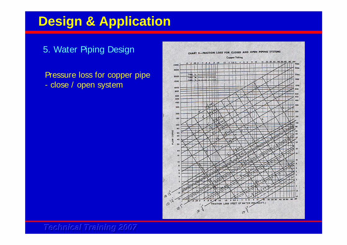
Pressure loss for copper pipe- close / open system
5. Water Piping Design
Design & Application
Technical Training 2007Technical Training 2007Technical Training 2007
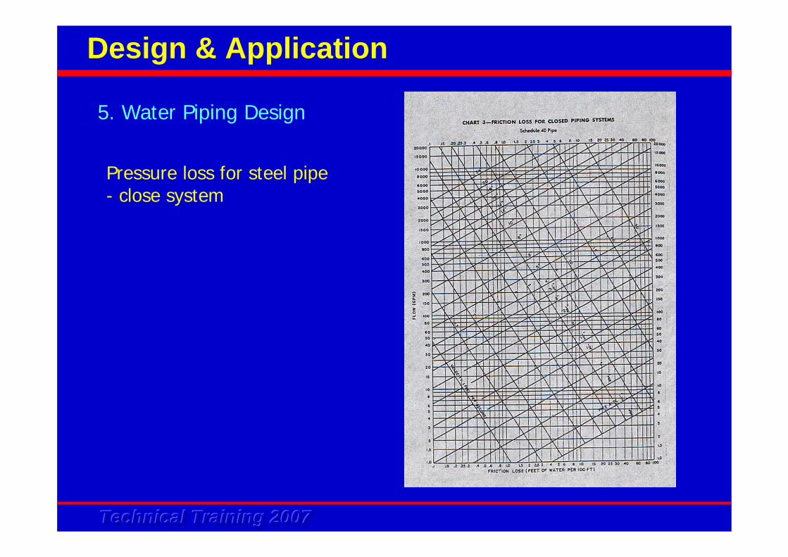
Pressure loss for steel pipe- close system
5. Water Piping Design
Design & Application
Technical Training 2007Technical Training 2007Technical Training 2007
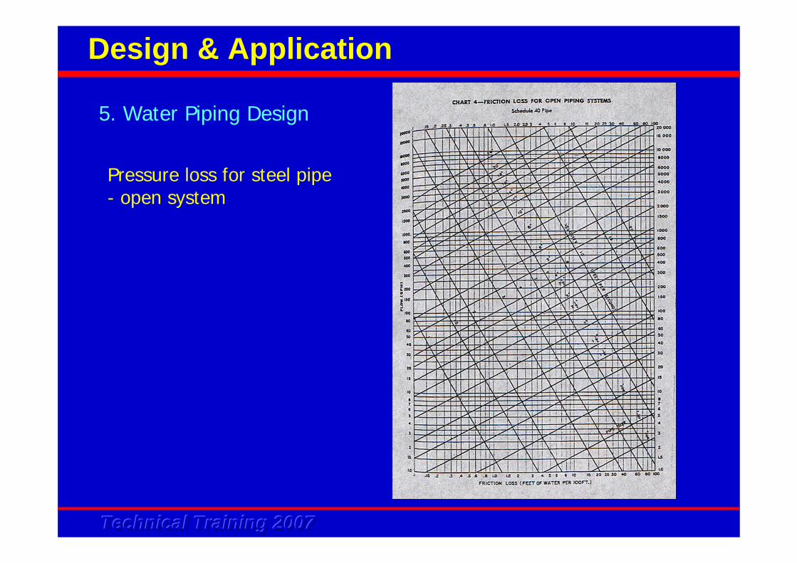
Pressure loss for steel pipe- open system
5. Water Piping Design
Design & Application
Technical Training 2007Technical Training 2007Technical Training 2007
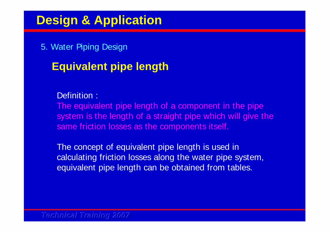
Definition :The equivalent pipe length of a component in the pipe system is the length of a straight pipe which will give the same friction losses as the components itself.
The concept of equivalent pipe length is used in calculating friction losses along the water pipe system, equivalent pipe length can be obtained from tables.
5. Water Piping Design
Design & Application
Equivalent pipe length
Technical Training 2007Technical Training 2007Technical Training 2007
5. Water Piping Design
Design & Application
Technical Training 2007Technical Training 2007Technical Training 2007
5. Water Piping Design
Design & Application
Technical Training 2007Technical Training 2007Technical Training 2007
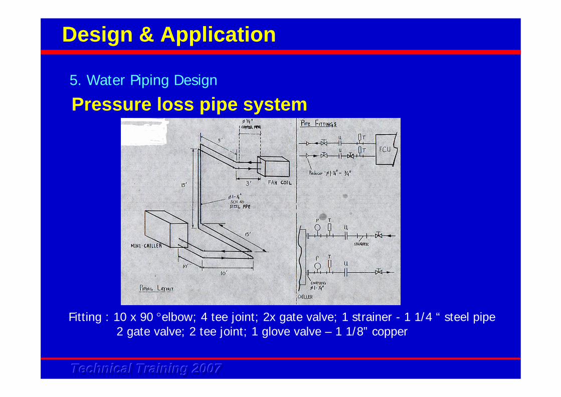
Fitting : 10 x 90 °elbow; 4 tee joint; 2x gate valve; 1 strainer - 1 1/4 “ steel pipe2 gate valve; 2 tee joint; 1 glove valve – 1 1/8” copper
Pressure loss pipe system5. Water Piping Design
Design & Application
Technical Training 2007Technical Training 2007Technical Training 2007
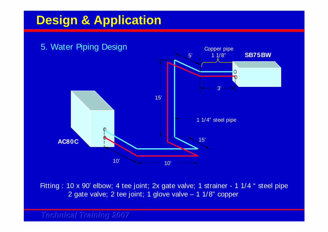
Fitting : 10 x 90° elbow; 4 tee joint; 2x gate valve; 1 strainer - 1 1/4 “ steel pipe2 gate valve; 2 tee joint; 1 glove valve – 1 1/8” copper
10’ 10’
15’
15’
3’
5’Copper pipe
1 1/8”
1 1/4” steel pipe
AC80C
SB75BW5. Water Piping Design
Design & Application
Technical Training 2007Technical Training 2007Technical Training 2007
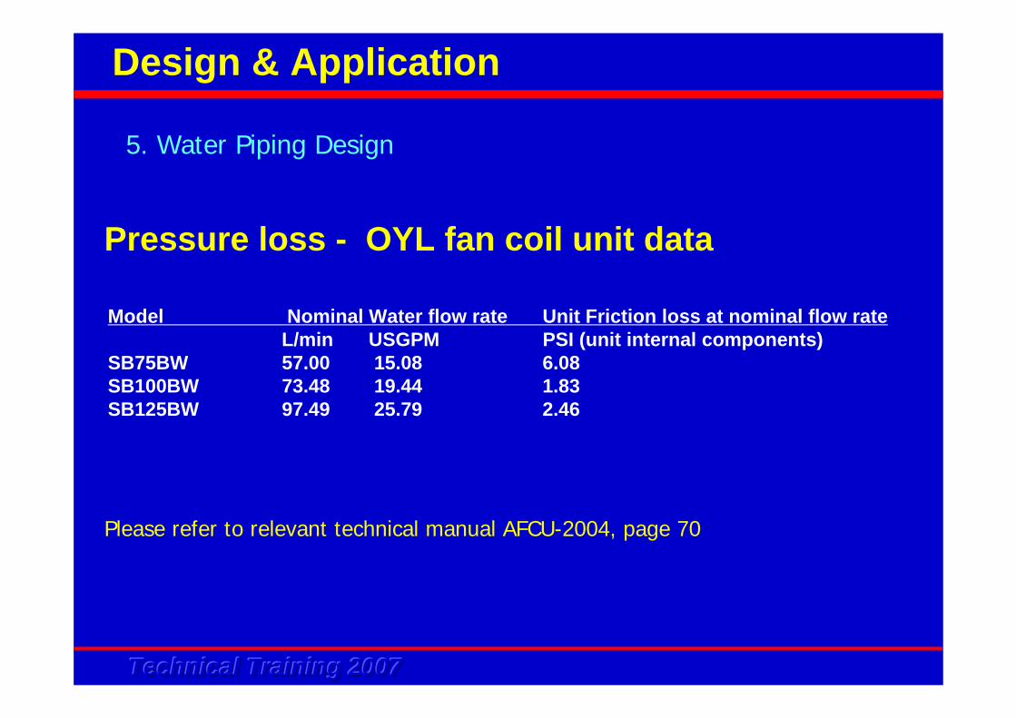
Pressure loss - OYL fan coil unit data
Model Nominal Water flow rate Unit Friction loss at nominal flow rateL/min USGPM PSI (unit internal components)
SB75BW 57.00 15.08 6.08SB100BW 73.48 19.44 1.83SB125BW 97.49 25.79 2.46
Please refer to relevant technical manual AFCU-2004, page 70
5. Water Piping Design
Design & Application
Technical Training 2007Technical Training 2007Technical Training 2007
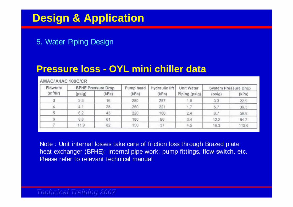
Pressure loss - OYL mini chiller data
Note : Unit internal losses take care of friction loss through Brazed plate heat exchanger (BPHE); internal pipe work; pump fittings, flow switch, etc.Please refer to relevant technical manual
5. Water Piping Design
Design & Application
Technical Training 2007Technical Training 2007Technical Training 2007
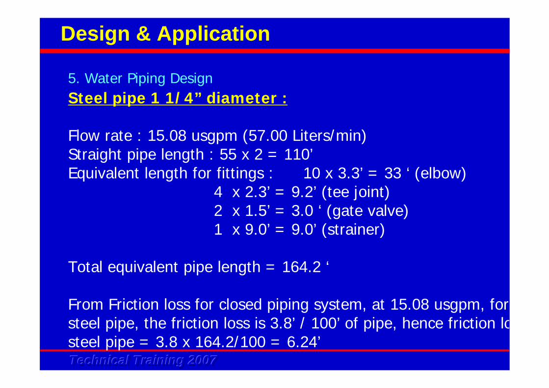
Steel pipe 1 1/4” diameter :
Flow rate : 15.08 usgpm (57.00 Liters/min)Straight pipe length : 55 x 2 = 110’Equivalent length for fittings : 10 x 3.3’ = 33 ‘ (elbow)
4 x 2.3’ = 9.2’ (tee joint)2 x 1.5’ = 3.0 ‘ (gate valve)1 x 9.0’ = 9.0’ (strainer)
Total equivalent pipe length = 164.2 ‘
From Friction loss for closed piping system, at 15.08 usgpm, forsteel pipe, the friction loss is 3.8’ / 100’ of pipe, hence friction losteel pipe = 3.8 x 164.2/100 = 6.24’
5. Water Piping Design
Design & Application
Technical Training 2007Technical Training 2007Technical Training 2007
5. Water Piping Design
Design & Application
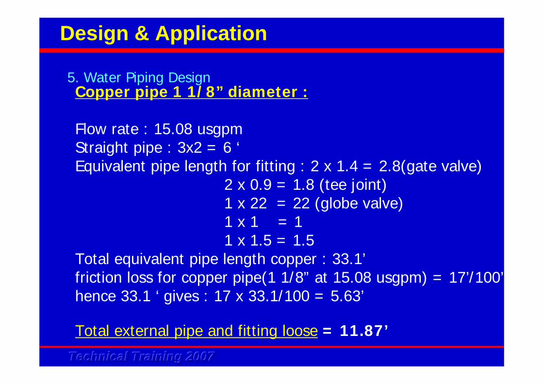
Total external pipe and fitting loose = 11.87’
Copper pipe 1 1/8” diameter :
Flow rate : 15.08 usgpmStraight pipe : 3x2 = 6 ‘Equivalent pipe length for fitting : 2 x 1.4 = 2.8(gate valve)
2 x 0.9 = 1.8 (tee joint)1 x 22 = 22 (globe valve)1 x 1 = 11 x 1.5 = 1.5
Total equivalent pipe length copper : 33.1’friction loss for copper pipe(1 1/8” at 15.08 usgpm) = 17’/100’hence 33.1 ‘ gives : 17 x 33.1/100 = 5.63’
Technical Training 2007Technical Training 2007Technical Training 2007
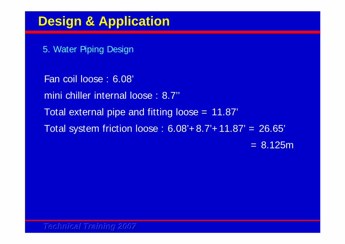
Fan coil loose : 6.08’
mini chiller internal loose : 8.7’’
Total external pipe and fitting loose = 11.87’
Total system friction loose : 6.08’+8.7’+11.87’ = 26.65’
= 8.125m
5. Water Piping Design
Design & Application
Technical Training 2007Technical Training 2007Technical Training 2007
Pump is one of the fundamental component in the system. It
circulates water through all the components in the system.
Pump is a built in component in OYL mini chiller. Basic
understanding about the pump characteristic is important.
6. Pump Selection
Design & Application
Technical Training 2007Technical Training 2007Technical Training 2007
Primary - secondary pump
If the built in pump in the mini chiller is not able to deliver the head pressure required to the load even in a close loop system :
• Change the existing pump to a higher head pump• Install a booster pump - primary - secondary pump system
6. Pump Selection
Design & Application
Technical Training 2007Technical Training 2007Technical Training 2007
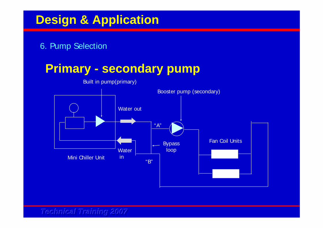
Primary - secondary pump
6. Pump Selection
Design & Application
Water out
WaterinMini Chiller Unit
Booster pump (secondary)
Bypass loop
“A”
“B”
Fan Coil Units
Built in pump(primary)
Technical Training 2007Technical Training 2007Technical Training 2007
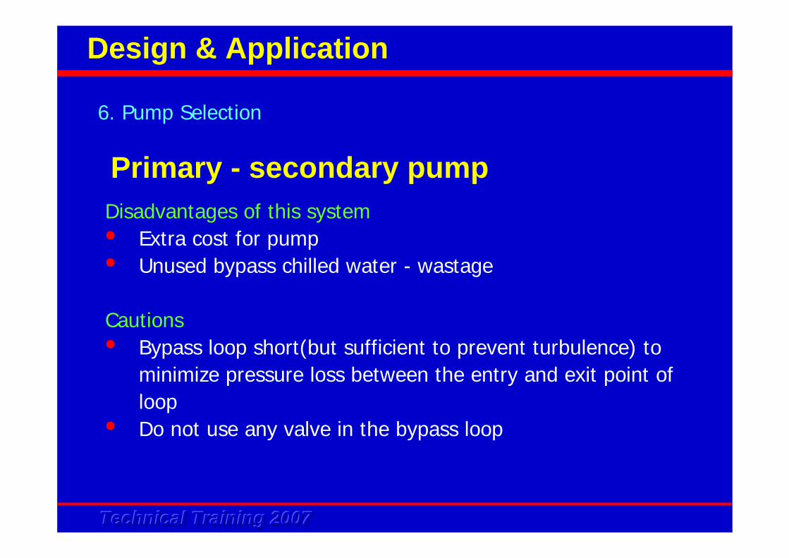
Disadvantages of this system• Extra cost for pump• Unused bypass chilled water - wastage
Cautions• Bypass loop short(but sufficient to prevent turbulence) to
minimize pressure loss between the entry and exit point of loop
• Do not use any valve in the bypass loop
6. Pump Selection
Design & Application
Primary - secondary pump
Technical Training 2007Technical Training 2007Technical Training 2007
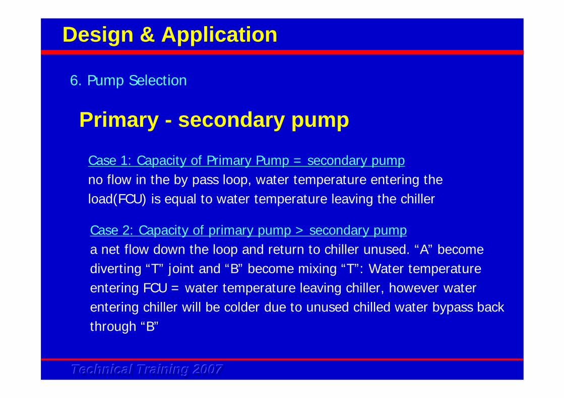
Case 1: Capacity of Primary Pump = secondary pumpno flow in the by pass loop, water temperature entering the load(FCU) is equal to water temperature leaving the chiller
Case 2: Capacity of primary pump > secondary pumpa net flow down the loop and return to chiller unused. “A” become diverting “T” joint and “B” become mixing “T”: Water temperature entering FCU = water temperature leaving chiller, however water entering chiller will be colder due to unused chilled water bypass back through “B”
6. Pump Selection
Design & Application
Primary - secondary pump
Technical Training 2007Technical Training 2007Technical Training 2007
Case 3: Capacity of primary pump < secondary pump
a net flow up the loop from “B”. “A” become a mixing point and “B”
become diverting “T”. Water temperature entering FCU will be in
between the water temperature leaving the chiller and the water
temperature entering Chiller
6. Pump Selection
Design & Application
Primary - secondary pump
Technical Training 2007Technical Training 2007Technical Training 2007
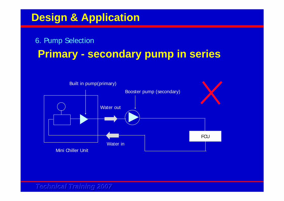
Primary - secondary pump in series6. Pump Selection
Design & Application
Water out
Water inMini Chiller Unit
FCU
Built in pump(primary)
Booster pump (secondary)
Technical Training 2007Technical Training 2007Technical Training 2007
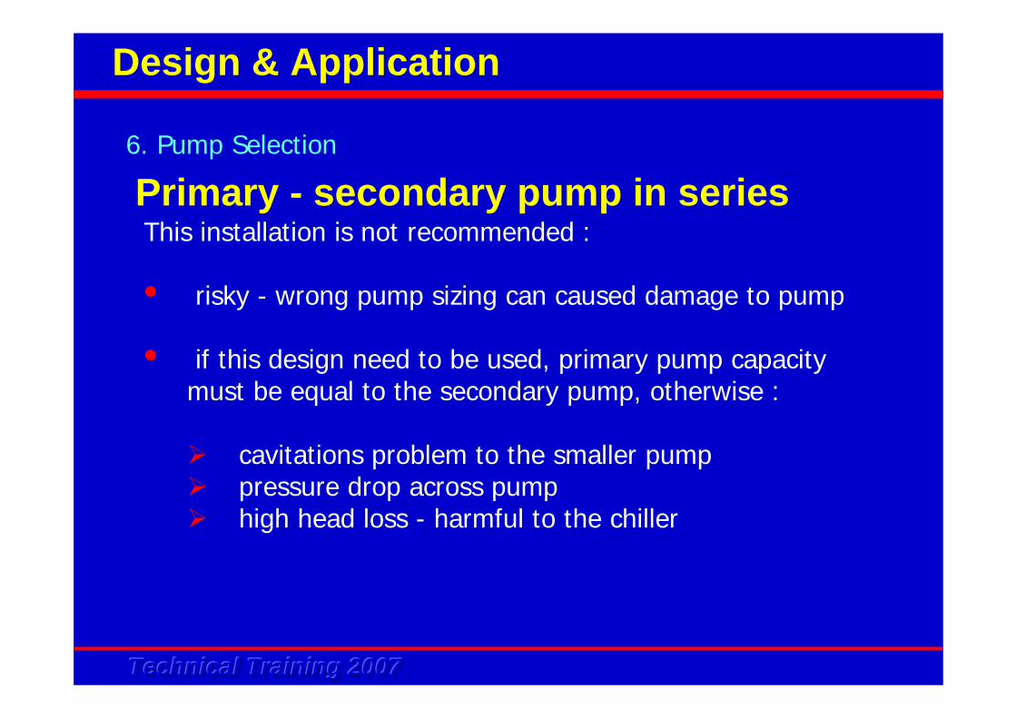
This installation is not recommended :
• risky - wrong pump sizing can caused damage to pump
• if this design need to be used, primary pump capacity must be equal to the secondary pump, otherwise :
cavitations problem to the smaller pumppressure drop across pumphigh head loss - harmful to the chiller
6. Pump Selection
Design & Application
Primary - secondary pump in series
Technical Training 2007Technical Training 2007Technical Training 2007
7. Multiple Chiller Selection
Design & Application
Primary - secondary pump in series
In the cases of multiple chiller need to be used,there are few possible installation method :
• Common supply and return headers• Primary - secondary system• Common tank system
Technical Training 2007Technical Training 2007Technical Training 2007
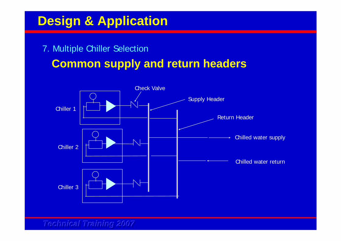
Common supply and return headers7. Multiple Chiller Selection
Design & Application
Chiller 1
Chiller 2
Chiller 3
Check Valve
Supply Header
Return Header
Chilled water supply
Chilled water return
Technical Training 2007Technical Training 2007Technical Training 2007
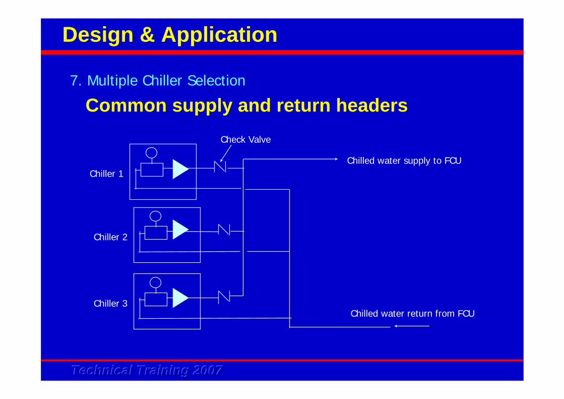
7. Multiple Chiller Selection
Design & Application
Chiller 1
Chiller 2
Chiller 3
Check Valve
Chilled water supply to FCU
Chilled water return from FCU
Common supply and return headers
Technical Training 2007Technical Training 2007Technical Training 2007
Most common and preferred• Low installation cost• Chiller set at different return water temperature - load staging• Check valve to prevent back flush of water • Drawbacks
proper balancing of water flow rate through each chiller is crucialAny chiller off, water flow rate to the FCU will be affected. To overcome this, it is necessary to wire the chiller controls for continuos pump running as long as one fan coil is in operationOne supply line, less flexibility in water distribution control, i.e. the highest pressure losses zone might be affected
7. Multiple Chiller Selection
Design & Application
Common supply and return headers
Technical Training 2007Technical Training 2007Technical Training 2007
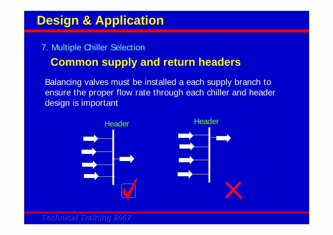
Balancing valves must be installed a each supply branch to ensure the proper flow rate through each chiller and header design is important
Header Header
7. Multiple Chiller Selection
Design & Application
Common supply and return headers
Technical Training 2007Technical Training 2007Technical Training 2007
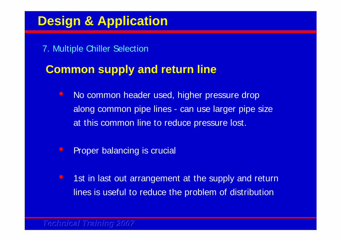
Common supply and return line
• No common header used, higher pressure drop
along common pipe lines - can use larger pipe size
at this common line to reduce pressure lost.
• Proper balancing is crucial
• 1st in last out arrangement at the supply and return
lines is useful to reduce the problem of distribution
7. Multiple Chiller Selection
Design & Application
Technical Training 2007Technical Training 2007Technical Training 2007
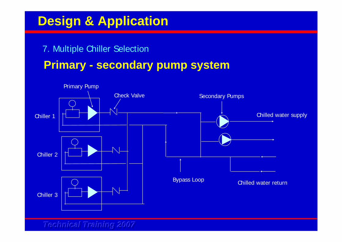
Primary - secondary pump system7. Multiple Chiller Selection
Design & Application
Chiller 1
Chiller 2
Chiller 3
Check Valve
Chilled water supply
Chilled water returnBypass Loop
Secondary Pumps
Primary Pump
Technical Training 2007Technical Training 2007Technical Training 2007
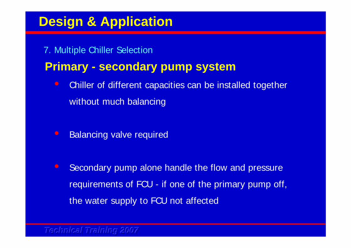
• Chiller of different capacities can be installed together
without much balancing
• Balancing valve required
• Secondary pump alone handle the flow and pressure
requirements of FCU - if one of the primary pump off,
the water supply to FCU not affected
7. Multiple Chiller Selection
Design & Application
Primary - secondary pump system
Technical Training 2007Technical Training 2007Technical Training 2007
7. Multiple Chiller Selection
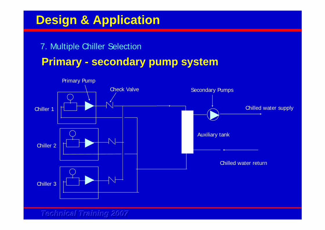
Design & Application
Primary - secondary pump system
Chiller 1
Chiller 2
Chiller 3
Check Valve
Chilled water supply
Chilled water return
Secondary Pumps
Auxiliary tank
Primary Pump
Technical Training 2007Technical Training 2007Technical Training 2007
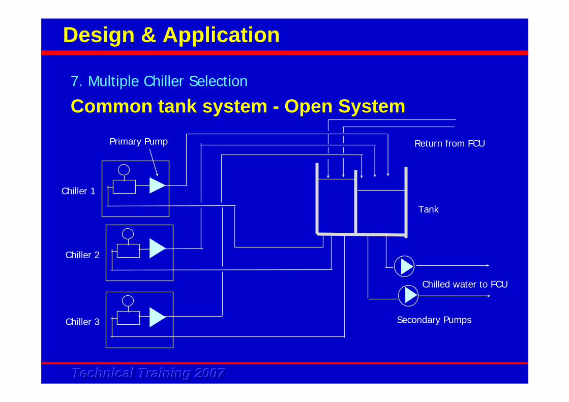
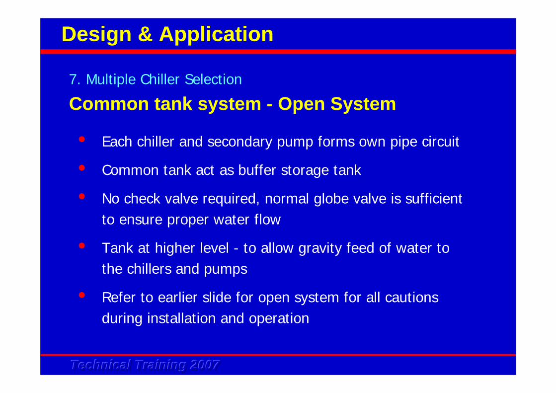
Common tank system - Open System7. Multiple Chiller Selection
Design & Application
Chiller 1
Chiller 2
Chiller 3
Chilled water to FCU
Secondary Pumps
Primary Pump
Tank
Return from FCU
Technical Training 2007Technical Training 2007Technical Training 2007
• Each chiller and secondary pump forms own pipe circuit
• Common tank act as buffer storage tank
• No check valve required, normal globe valve is sufficient to ensure proper water flow
• Tank at higher level - to allow gravity feed of water to the chillers and pumps
• Refer to earlier slide for open system for all cautions during installation and operation
7. Multiple Chiller Selection
Design & Application
Common tank system - Open System
Technical Training 2007Technical Training 2007Technical Training 2007
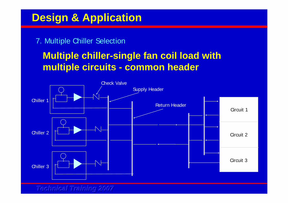
Multiple chiller-single fan coil load with multiple circuits - common header
7. Multiple Chiller Selection
Design & Application
Chiller 1
Chiller 2
Chiller 3
Check ValveSupply Header
Return Header
Circuit 2
Circuit 1
Circuit 3
Technical Training 2007Technical Training 2007Technical Training 2007
7. Multiple Chiller Selection
Design & Application
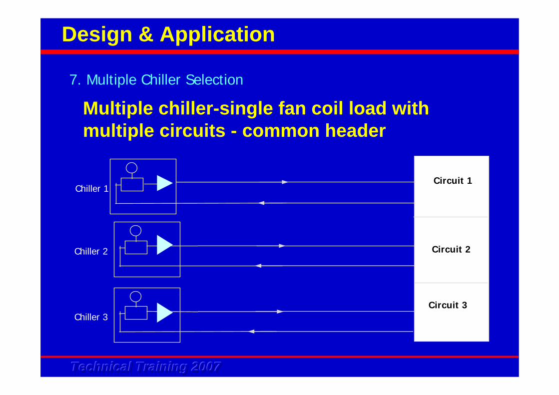
Multiple chiller-single fan coil load with multiple circuits - common header
Chiller 1
Chiller 2
Chiller 3
Circuit 2
Circuit 1
Circuit 3
Technical Training 2007Technical Training 2007Technical Training 2007
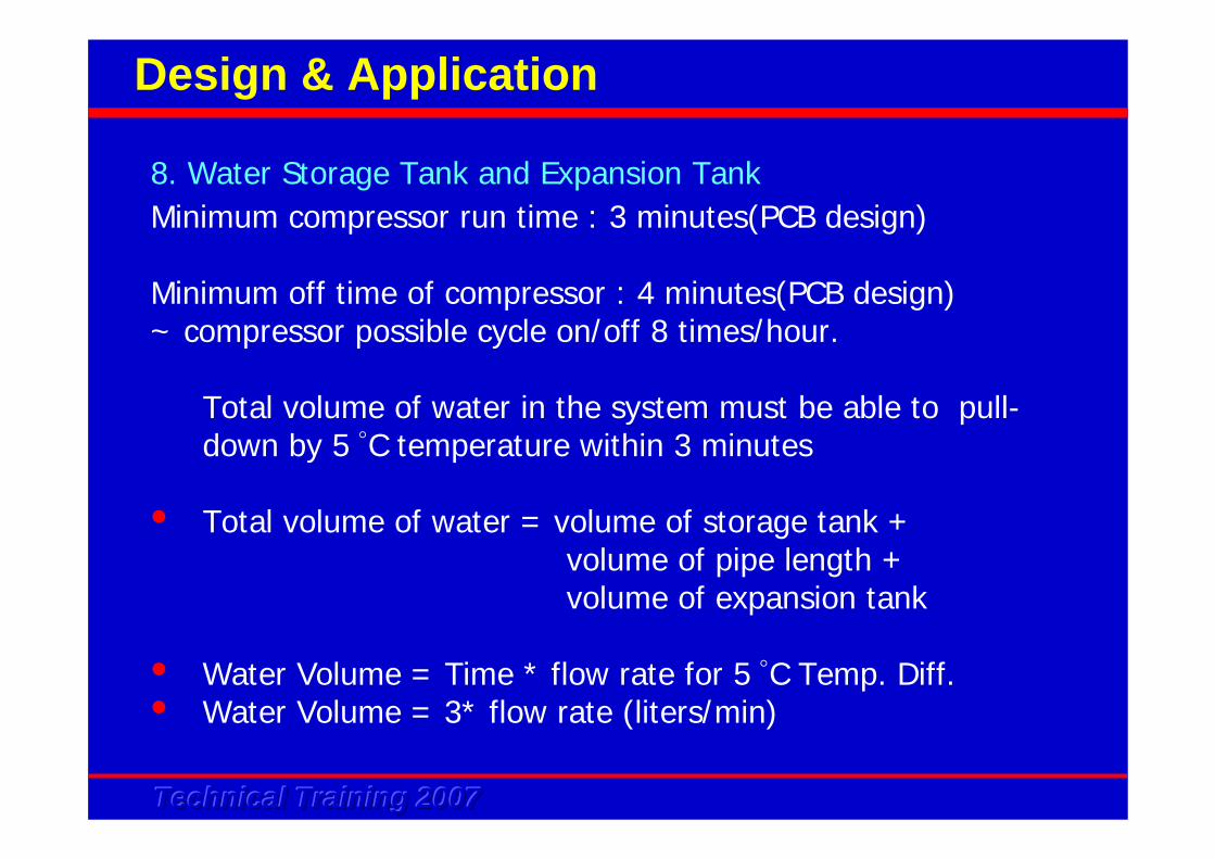
Minimum compressor run time : 3 minutes(PCB design)
Minimum off time of compressor : 4 minutes(PCB design)~ compressor possible cycle on/off 8 times/hour.
Total volume of water in the system must be able to pull-down by 5 °C temperature within 3 minutes
• Total volume of water = volume of storage tank + volume of pipe length + volume of expansion tank
• Water Volume = Time * flow rate for 5 °C Temp. Diff. • Water Volume = 3* flow rate (liters/min)
8. Water Storage Tank and Expansion Tank
Design & Application
Technical Training 2007Technical Training 2007Technical Training 2007
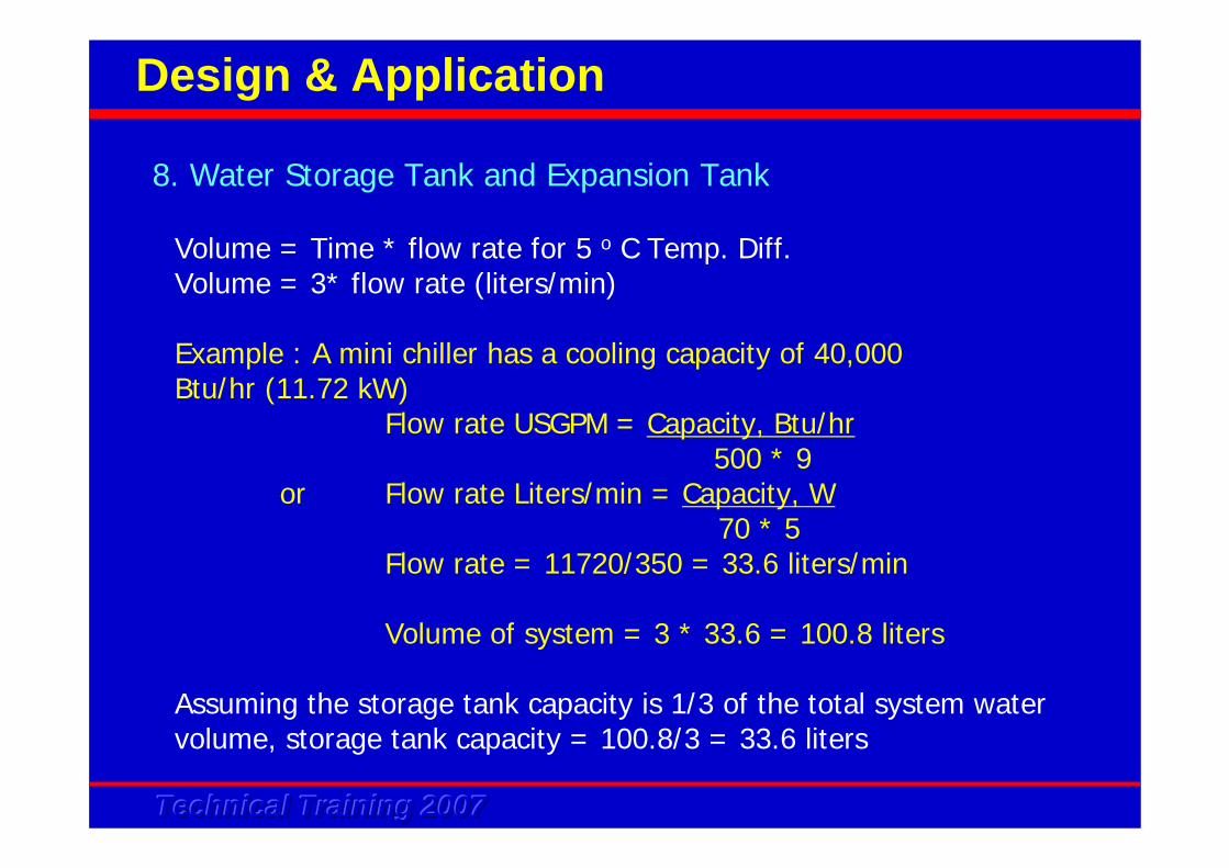
Volume = Time * flow rate for 5 o C Temp. Diff. Volume = 3* flow rate (liters/min)
Example : A mini chiller has a cooling capacity of 40,000 Btu/hr (11.72 kW)
Flow rate USGPM = Capacity, Btu/hr500 * 9
or Flow rate Liters/min = Capacity, W70 * 5
Flow rate = 11720/350 = 33.6 liters/min
Volume of system = 3 * 33.6 = 100.8 liters
Assuming the storage tank capacity is 1/3 of the total system water volume, storage tank capacity = 100.8/3 = 33.6 liters
8. Water Storage Tank and Expansion Tank
Design & Application
Technical Training 2007Technical Training 2007Technical Training 2007
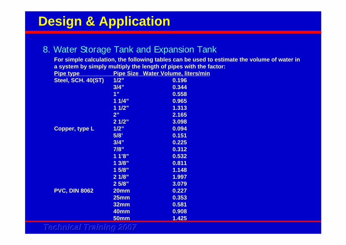
For simple calculation, the following tables can be used to estimate the volume of water in a system by simply multiply the length of pipes with the factor:Pipe type Pipe Size Water Volume, liters/minSteel, SCH. 40(ST) 1/2” 0.196
3/4” 0.3441” 0.5581 1/4” 0.9651 1/2” 1.3132” 2.1652 1/2” 3.098
Copper, type L 1/2” 0.0945/8’ 0.1513/4” 0.2257/8” 0.3121 1’8” 0.5321 3/8” 0.8111 5/8” 1.1482 1/8” 1.9972 5/8” 3.079
PVC, DIN 8062 20mm 0.22725mm 0.35332mm 0.58140mm 0.90850mm 1.425
Design & Application
8. Water Storage Tank and Expansion Tank
Technical Training 2007Technical Training 2007Technical Training 2007
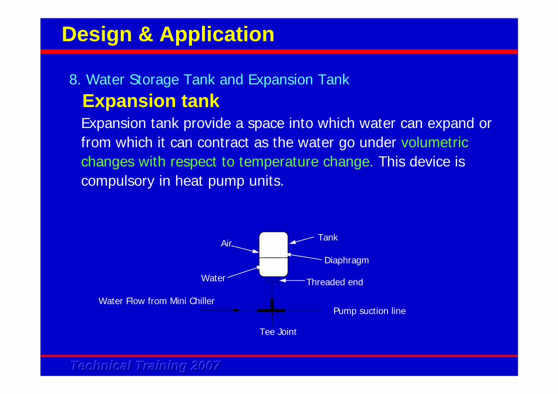
Expansion tankExpansion tank provide a space into which water can expand or from which it can contract as the water go under volumetric changes with respect to temperature change. This device is compulsory in heat pump units.
Air
Water
Tank
Diaphragm
Threaded end
Tee Joint
Pump suction lineWater Flow from Mini Chiller
8. Water Storage Tank and Expansion Tank
Design & Application
Technical Training 2007Technical Training 2007Technical Training 2007
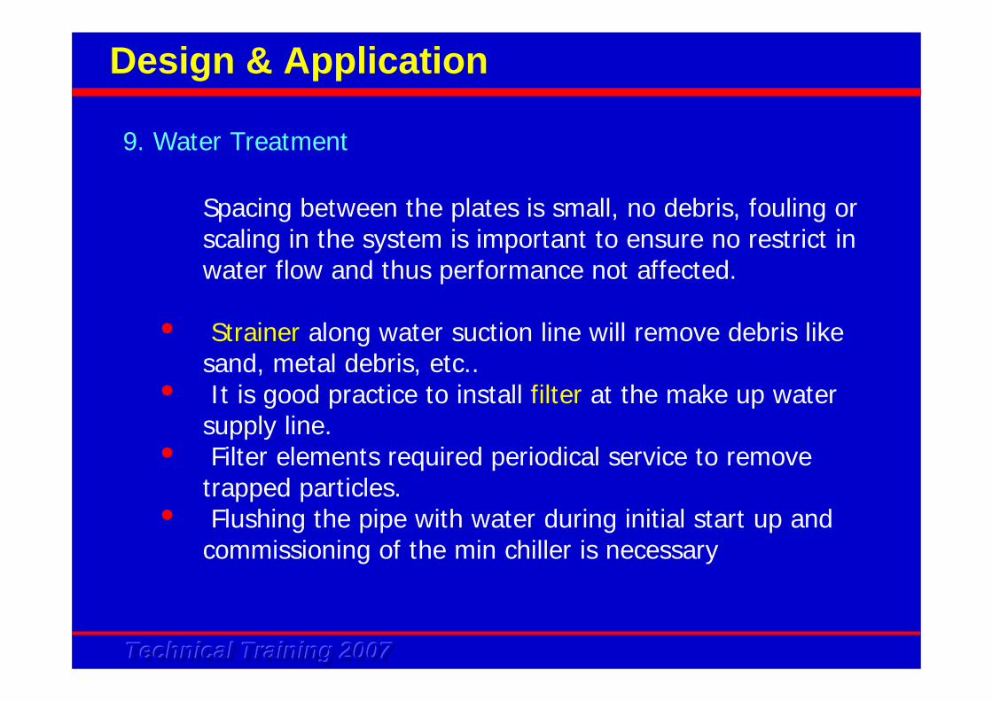
Spacing between the plates is small, no debris, fouling or scaling in the system is important to ensure no restrict in water flow and thus performance not affected.
• Strainer along water suction line will remove debris like sand, metal debris, etc..
• It is good practice to install filter at the make up water supply line.
• Filter elements required periodical service to remove trapped particles.
• Flushing the pipe with water during initial start up and commissioning of the min chiller is necessary
9. Water Treatment
Design & Application
Technical Training 2007Technical Training 2007Technical Training 2007
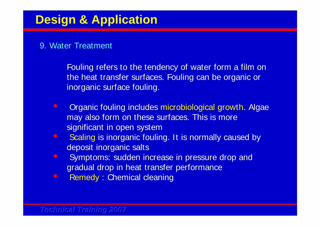
Fouling refers to the tendency of water form a film on the heat transfer surfaces. Fouling can be organic or inorganic surface fouling.
• Organic fouling includes microbiological growth. Algae may also form on these surfaces. This is more significant in open system
• Scaling is inorganic fouling. It is normally caused by deposit inorganic salts
• Symptoms: sudden increase in pressure drop and gradual drop in heat transfer performance
• Remedy : Chemical cleaning
9. Water Treatment
Design & Application

Technical Training 2007Technical Training 2007Technical Training 2007
• Organic fouling can be removed by use of alkaline cleaningagent like sodium hydroxide at 5% concentration. Refer to chemical manufacturer for more details instruction. Make sure the excess chemical is fully clean up from the system
• Inorganic fouling most commonly need acidic based cleaningagent. Mineral acids has strong ability to dissolve scales, but attack/corrode stainless steel and copper parts, hence is not recommended. Organic acids at 2 - 5% concentration is more ideal when used to clean BPHE.
• Refer to chemical manufacturer recommendation on the dosage requirement. Upon completion, flush with clean water to remove excess acids.
• It is recommended that the water to be replaced at least once a year to prevent fouling on the BPHE
9. Water Treatment
Design & Application
Technical Training 2007Technical Training 2007Technical Training 2007
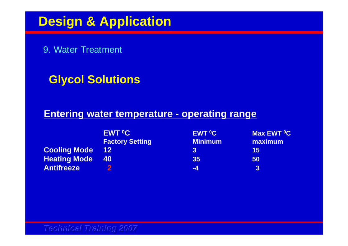
Glycol Solutions
Entering water temperature - operating range
EWT 0C EWT 0C Max EWT 0CFactory Setting Minimum maximum
Cooling Mode 12 3 15Heating Mode 40 35 50Antifreeze 2 -4 3
9. Water Treatment
Design & Application
Technical Training 2007Technical Training 2007Technical Training 2007
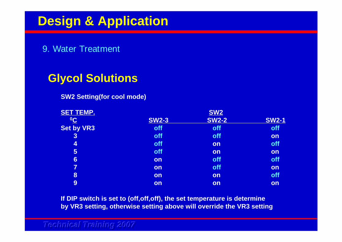
SW2 Setting(for cool mode)
SET TEMP. SW20C SW2-3 SW2-2 SW2-1
Set by VR3 off off off3 off off on4 off on off5 off on on6 on off off7 on off on8 on on off9 on on on
If DIP switch is set to (off,off,off), the set temperature is determineby VR3 setting, otherwise setting above will override the VR3 setting
9. Water Treatment
Design & Application
Glycol Solutions
Technical Training 2007Technical Training 2007Technical Training 2007
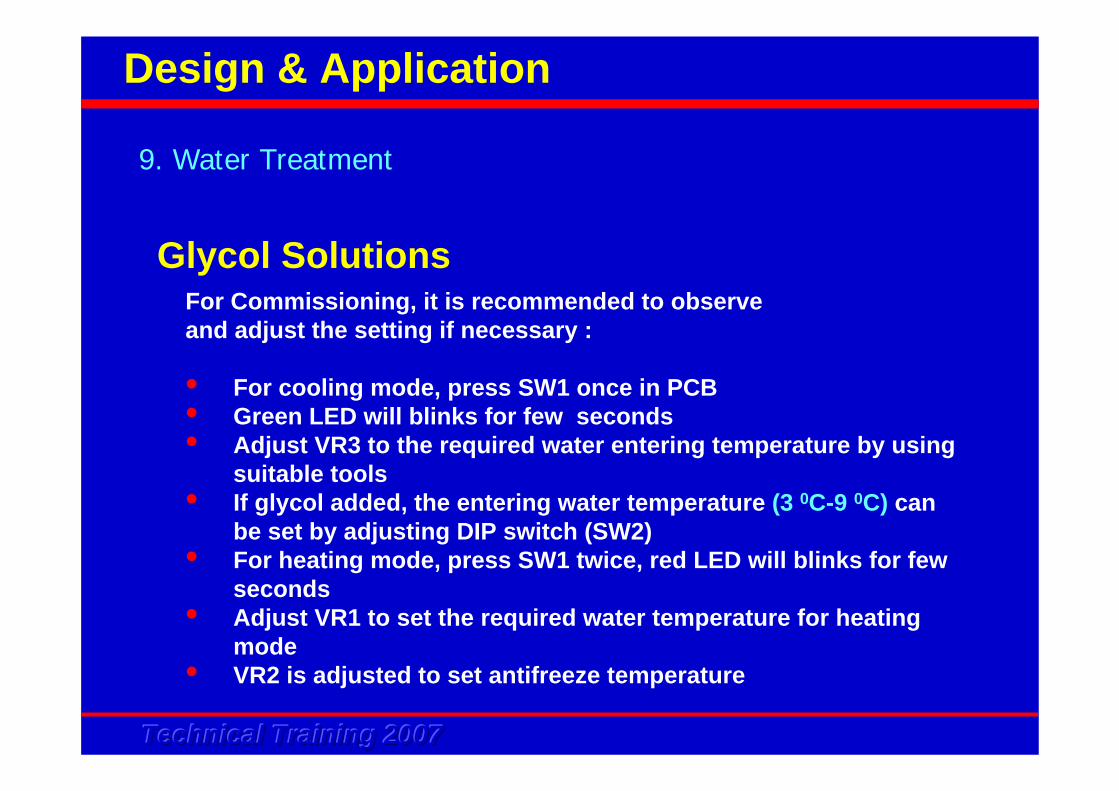
For Commissioning, it is recommended to observeand adjust the setting if necessary :
• For cooling mode, press SW1 once in PCB• Green LED will blinks for few seconds• Adjust VR3 to the required water entering temperature by using
suitable tools• If glycol added, the entering water temperature (3 0C-9 0C) can
be set by adjusting DIP switch (SW2)• For heating mode, press SW1 twice, red LED will blinks for few
seconds• Adjust VR1 to set the required water temperature for heating
mode• VR2 is adjusted to set antifreeze temperature
9. Water Treatment
Design & Application
Glycol Solutions
Technical Training 2007Technical Training 2007Technical Training 2007
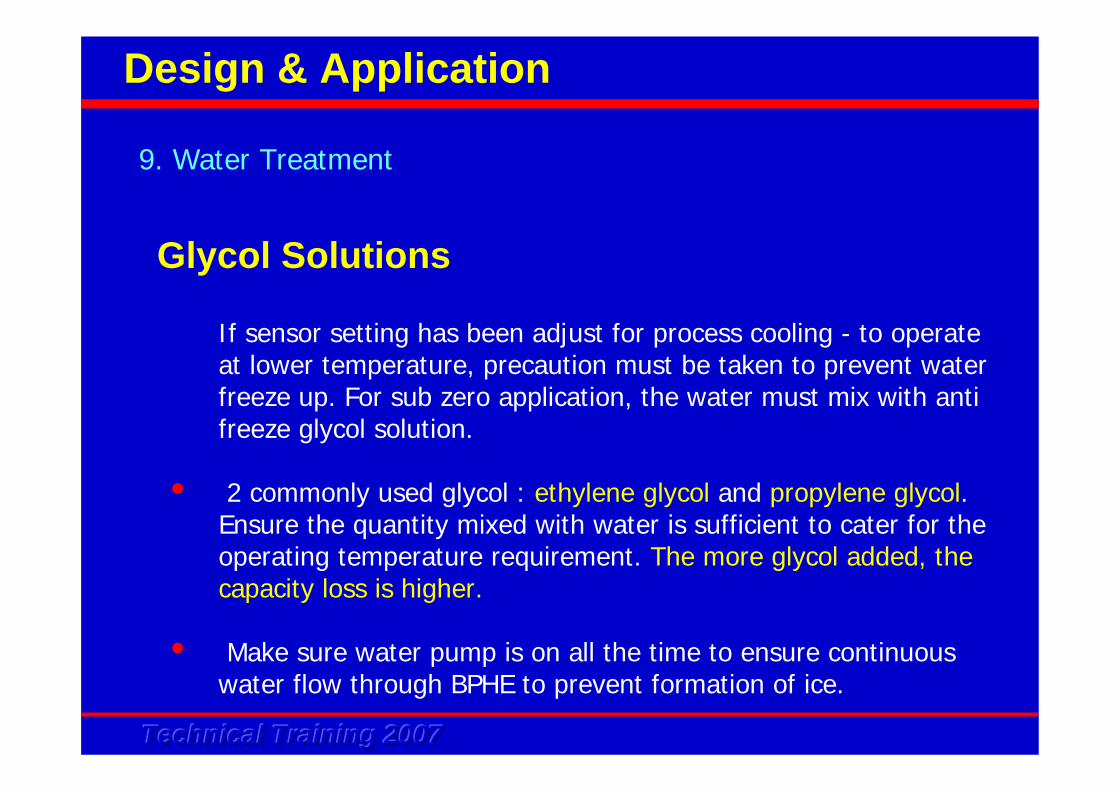
If sensor setting has been adjust for process cooling - to operate at lower temperature, precaution must be taken to prevent water freeze up. For sub zero application, the water must mix with anti freeze glycol solution.
• 2 commonly used glycol : ethylene glycol and propylene glycol. Ensure the quantity mixed with water is sufficient to cater for the operating temperature requirement. The more glycol added, the capacity loss is higher.
• Make sure water pump is on all the time to ensure continuous water flow through BPHE to prevent formation of ice.
9. Water Treatment
Design & Application
Glycol Solutions
Technical Training 2007Technical Training 2007Technical Training 2007
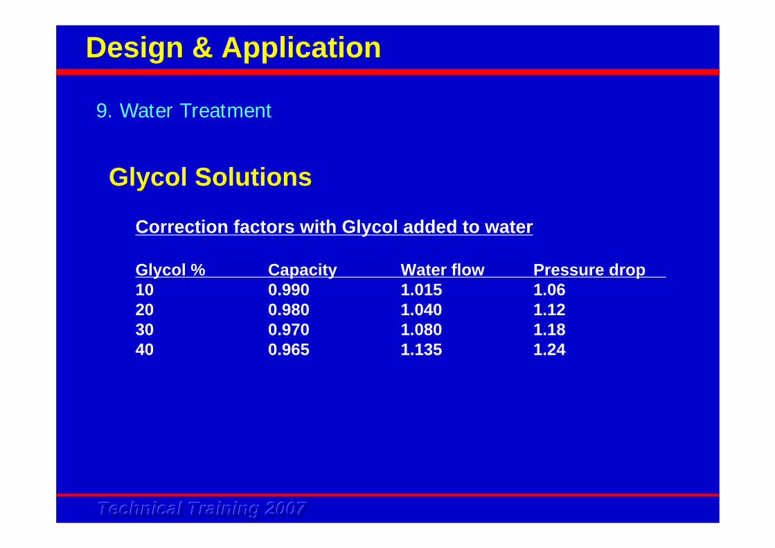
Correction factors with Glycol added to water
Glycol % Capacity Water flow Pressure drop10 0.990 1.015 1.0620 0.980 1.040 1.1230 0.970 1.080 1.1840 0.965 1.135 1.24
9. Water Treatment
Design & Application
Glycol Solutions
Technical Training 2007Technical Training 2007Technical Training 2007
9. Water Treatment
Design & Application
Glycol Solutions
Technical Training 2007Technical Training 2007Technical Training 2007
Pipe being insulated for the following purposes :
• Prevent heat gain / loss from the water in the pipe• Prevent condensation when chilled water flow in the pipe• Prevent injury due to hot water flow in the pipe
To do a calculation of insulation thickness, one must know :
• Insulation material thermal conductivity coefficient (K)• Pipe size• Air condition at the site of installation (Dry bulb and humidity)• Convective heat transfer coefficient (H)• A simplify spread sheet is provided to estimate the insulation
thickness
10. Pipe Insulation Requirement
Design & Application
Technical Training 2007Technical Training 2007Technical Training 2007
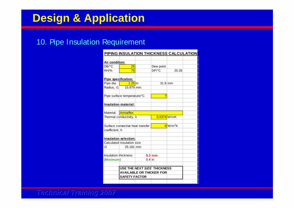
PIPING INSULATION THICKNESS CALCULATION:
Air condition:DB/°C 25 Dew pointRH/% 75 DP/°C 20.26
Pipe specification:Pipe dia. 1.25 in 31.8 mmRadius, r1 15.879 mm
Pipe surface temperature/°C 7
Insulation material:
Material: ArmarflexThermal conductivity, k 0.0374 W/mK
Surface convective heat transfer 9 W/m2Kcoefficient, h
Insulation selection:Calculated insulation sizer2 25.181 mm
Insulation thickness 9.3 mm(Minimum) 0.4 in
USE THE NEXT SIZE THICKNESSAVAILABLE OR THICKER FORSAFETY FACTOR
10. Pipe Insulation Requirement
Design & Application
Technical Training 2007Technical Training 2007Technical Training 2007
Few application samples will be provided, however with the following considerations:
• The option “Alarm LED” from terminal AL1 and AL2 in mini chiller is meant to be installed into the external control switch board - to indicate if an abnormal operation has occur. The PCB will give out a signal to light up the LED when any of the protection devices trip.
• The option “Remote Switch” may be located at a convenient place for easy access to the user. It may be placed inside the switchboard. It can also act as an emergency switch to stop the chiller
• The power supply for the fan coil units are separated from the mini chiller
10. Pipe Insulation Requirement
Design & Application
Back To Content