inverted sine pulse width modulation approaches for power quality enhancement with custom power...
TRANSCRIPT

8/9/2019 Inverted Sine Pulse Width Modulation Approaches for Power Quality Enhancement with Custom Power Devices
http://slidepdf.com/reader/full/inverted-sine-pulse-width-modulation-approaches-for-power-quality-enhancement 1/13
IOSR Journal of Electrical and Electronics Engineering (IOSR-JEEE)e-ISSN: 2278-1676,p-ISSN: 2320-3331, Volume 10, Issue 2 Ver. III (Mar – Apr. 2015), PP 33-45www.iosrjournals.org
DOI: 10.9790/1676-10233345 www.iosrjournals.org 33 | Page
Inverted Sine Pulse Width Modulation Approaches for PowerQuality Enhancement with Custom Power Devices
T.Sridevi #1
≠1 Assistant professor, Sri Sairam Institute of Technology, Chennai,Tamilnadu
Abstract: This paper addresses the application of a new Pulse-Wide Modulation (PWM) technique calledinverted-sine PWM (ISPWM). These technique can be used to control Voltage Source Converters (VSC) ofcustom power devices which provide valuable supply to customers in low voltage distribution networks. The
ISPWM technique generates lower voltage Total Harmonic Distortion (THD) in comparison with conventionalSinusoidal PWM (SPWM) technique. The proposed switching technique has been implemented on DistributionStatic Compensator (DSTATCOM) and Dynamic Voltage Restorer (DVR). Simulation results with MATLABSimulink show the effectiveness of the proposed switching techniques in the reduction of Total Harmonic
Distortion (THD) than conventional sine PWM technique.
Keywords: PWM, Power Quality, Harmonics, VSC, D-STATCOM, DVR, Custom Power, Voltage Sag.
I. IntroductionOne of the most common power quality problems is Voltage sag. Voltage sag is a reduction in the
RMS voltage in the range of 0.1 to 0.9 p.u. (retained) for duration greater than half a mains cycle and less than 1minute. Voltage sags caused by faults, increased load demand and transitional events such as large motorstarting. There are different ways to mitigate voltage dips in distribution systems.
Fig 1 waveform representing voltage sag,swell, impulse voltage
A custom power specification may include provision for (i) no power interruption (ii) Tight Voltageregulation including short duration sags or swells (iii) Low harmonic Voltages and (iv) Acceptance offluctuating and non linear loads without effect on terminal voltage. These devices are connected either in shuntor in series or in combination of both series and shunt. The series-connected device is dynamic voltage restorer(DVR) that is to inject a voltage of desired amplitude, frequency and phase between the PCC and the load inseries with the grid voltage. The shunt-connected device is distribution static compensator (DSTATCOM)
which is to dynamically inject a current of desired amplitude, frequency and phase into the grid. Powerelectronic converters which are main component in custom power devices introduce harmonics due to switchingoperation of thyristor. To reduce harmonics for power quality enhancement , PWM techniques called invertedsine PWM(ISPWM),Trapezoidal inverted sine PWM(TISPWM) and Sawtooth inverted sine PWM(SISPWM)techniques have been developed by using MATLAB simulink. These results are compared with sine PWM.

8/9/2019 Inverted Sine Pulse Width Modulation Approaches for Power Quality Enhancement with Custom Power Devices
http://slidepdf.com/reader/full/inverted-sine-pulse-width-modulation-approaches-for-power-quality-enhancement 2/13
Inverted Sine Pulse Width Modulation Approaches for Power Quality Enhancement with ….
DOI: 10.9790/1676-10233345 www.iosrjournals.org 34 | Page
II. Custom Power Devices2.1 Classification of custom power devices
Fig 2 Custom Power Distribution System
Custom power devices can be classified into two major categories. One is network configuring typeand the other is compensating type. The former changes the configuration of the power system network for
power quality enhancement.SSCL (Solid State Current Limiter), SSCB (Solid State Circuit Breaker) and SSTS
(Solid State Transfer Switch) are the most representative in this category.The compensating type devices are used for active filtering, load balancing, power factor correction
and voltage regulation. The family of compensating devices include DSTATCOM (Distribution Staticcompensator), DVR (Dynamic voltage restorer) and Unified power quality conditioner (UPQC) .DSTATCOMhas a similar structure and function to STATCOM in the transmission system.DSTATCOM is connected inshunt with the power system.DVR is a series connected device that injects a rapid series voltage to compensatethe supply voltage.
Fig 2.1 Configuration of Custom Power Devices
III. Distribution Static Synchronous Compensator (D-Statcom)3.1 Basic Principle of DSTATCOM
A DSTATCOM is a controlled reactive source, which includes a Voltage Source Converter (VSC) anda DC link capacitor connected in shunt, capable of generating and/or absorbing reactive power. The operating
principles of a DSTATCOM are based on the exact equivalence of the conventional rotating synchronouscompensator.
.Fig.3.1 Basic structure of DSTAT COM
The AC terminals of the VSC are connected to the Point of Common Coupling (PCC) through aninductance, which could be a filter inductance or the leakage inductance of the coupling transformer, as shownin figure 3.1. The DC side of the converter is connected to a DC capacitor, which carries the input ripple currentof the converter and is the main reactive energy storage element. This capacitor could be charged by a battery

8/9/2019 Inverted Sine Pulse Width Modulation Approaches for Power Quality Enhancement with Custom Power Devices
http://slidepdf.com/reader/full/inverted-sine-pulse-width-modulation-approaches-for-power-quality-enhancement 3/13
Inverted Sine Pulse Width Modulation Approaches for Power Quality Enhancement with ….
DOI: 10.9790/1676-10233345 www.iosrjournals.org 35 | Page
source, or could be recharged by the converter itself.. For a DSTATCOM used for voltage regulation at thePCC, the compensation should be such that the supply currents should lead the supply voltages. The controlstrategies are applied with DSTATCOM for harmonicmitigation.
3.2. Basic Configuration and Operation of D-STATCOMThe D-STATCOM is a three-phase and shunt connected power electronics based device. It isconnected near the load at the distribution systems. The major components of a DSTATCOM are shown infigure 3.2. It consists of a dc capacitor, three-phase inverter (IGBT, thyristor) module, ac filter, couplingtransformer and a control strategy. The basic electronic block of the D-STATCOM is the voltage-sourcedinverter that converts an input dc voltage into a three-phase output voltage at fundamental frequency.
Fig 3.2 Basic building blocks of D-STATCOM
In the figure 3.2,the controller of the D-STATCOM is used to operate the inverter in such a way thatthe phase angle between the inverter voltage and the line voltage is dynamically adjusted so that the D-STATCOM generates or absorbs the desired VAR at the point of connection. The phase of the output voltage ofthe thyristor-based inverter is controlled in the same way as the distribution system voltage, Vs.
IV. Dynamic Voltage Restorer (DVR)The DVR is a powerful controller commonly used for voltage sags mitigation. The DVR employs the
same blocks as the D-STATCOM, but in this application the coupling transformer is connected in series withthe AC system
. Fig.4 Schematic representation of DVR
The VSC generates a three-phase AC output voltage which can be controlled in phase and magnitude.These voltages are injected into the AC distribution system in order to maintain the load voltage at the desiredvoltage level.
Features of DVR• Voltages sag and swell compensation.• Line voltage harmonics compensation.• Reduction of transients in voltage.• Fault current limitations.
4.1 Principle of DVR Operation
A DVR is a solid state power electronics switching device consisting of either GTO or IGBT, acapacitor bank as an energy storage device and injection transformers. It is linked in series between adistribution system and a load that shown in figure. The basic idea of the DVR is to inject a controlled voltage

8/9/2019 Inverted Sine Pulse Width Modulation Approaches for Power Quality Enhancement with Custom Power Devices
http://slidepdf.com/reader/full/inverted-sine-pulse-width-modulation-approaches-for-power-quality-enhancement 4/13
Inverted Sine Pulse Width Modulation Approaches for Power Quality Enhancement with ….
DOI: 10.9790/1676-10233345 www.iosrjournals.org 36 | Page
generated by a forced commutated inverter in series to the bus voltage by means of an injection transformer. ADC to AC inverter regulates this voltage by using sinusoidal PWM technique.. However, when the voltage sagoccurs in distribution system, the DVR control system calculates and synthesizes the voltage required to
preserve output voltage to the load by injecting a controlled voltage with a certain magnitude and phase ang leinto the distribution system to the critical load.
Fig.4.1 Principle of DVR System
V. Basic Arrangement of DVR The DVR mainly consists of the following components.i. An injection transformerii. DC charging unitiii. Storage devicesiv. A voltage source converter(VSC)v. Harmonic filtervi. A control and protection system
Fig.5. Schematic diagram of DVR
5.1 Series Voltage Injection Transformers:In a three-phase system, either three single-phase transformer units or one three phase transformer unit
can be used for voltage injection purpose .The injection transformer comprises of two side voltages namely thehigh voltage side and low voltage side. Normally the high voltage side of the injection transformer is connectedin series to the distribution system while power circuit of the DVR can be connected at the low voltage side. The
basic function of the injection transformer is to increase the voltage supplied by the filtered VSI output to the
desired level while isolating the DVR circuit from the distribution network.
5.2 Energy Storage:The DVR needs real power for compensation purposes during voltage disturbances in the distribution
system. In this case the real power of the DVR must be supplied by energy storage when the voltagedisturbances exit. The energy storage such as a battery is responsible to supply an energy source in DC form.Energy storage consists of two types form. One using stored energy to supply the delivered power and the otherhaving no significant internal energy storage but instead energy is taken from the faulted grid supply during thesags. A shunt – converter or the rectifier is the main sources of the direct energy storage which is supplied toDVR. Flywheels, batteries, superconducting magnetic energy storage (SMES) and super capacitors can be usedas energy storage devices.
5.3 LC Filter
Basically filter unit consists of inductor (L) and capacitor (C). In DVR, filters are used to convert theinverted PWM waveform into a sinusoidal waveform. This can be achieved by eliminating the unwantedharmonic components generated by the VSI action. Higher orders harmonic components distort the

8/9/2019 Inverted Sine Pulse Width Modulation Approaches for Power Quality Enhancement with Custom Power Devices
http://slidepdf.com/reader/full/inverted-sine-pulse-width-modulation-approaches-for-power-quality-enhancement 5/13

8/9/2019 Inverted Sine Pulse Width Modulation Approaches for Power Quality Enhancement with Custom Power Devices
http://slidepdf.com/reader/full/inverted-sine-pulse-width-modulation-approaches-for-power-quality-enhancement 6/13
Inverted Sine Pulse Width Modulation Approaches for Power Quality Enhancement with ….
DOI: 10.9790/1676-10233345 www.iosrjournals.org 38 | Page
the PWM output is positive and When Vcontrol is smaller than Vcarrier, the PWM waveform is negative. Thefrequency of triangle waveform Vca rrier establishes the inverter’s switching frequency fs. We define themodulation index mi as follows:
mi = Vcontrol / Vtri
Where Vcontrol is the peak amplitude of the control signal and Vtri is the peak amplitude of the triangle signal(carrier).Also the frequency modulation ratio is defined as
mf = fs / f1mf is the ratio between the carrier and control frequency. The fundamental component (Vout)1 of the H bridgeoutput voltage (Vout)1 has the property as depicted in equation below in a linear modulation region:
(Vout) 1 = mi * Vd mi ≤ 1.0This equation shows that the amplitude of the fundamental component of the output voltage varies linearly withthe modulation index. The mi value from zero to one is defined as the linear control range of sinusoidal carrierPWM.
Fig.7.1. Sinusoidal Pulse Width Modulation
7.2. Proposed ISPWM TechniqueThe proposed ISPWM has new forms of carriers, carrier1 and carrier2, as shown in Fig. These
waveforms have been generated by inversion of ISPWM carrier of in half-cycle of power frequency and half-cycle of carrier frequency, respectively.
Fig.7.2 (a) Proposed ISPWM Carriers
The firing control signals have been generated by comparing sinusoidal reference signal (with thefrequency f and magnitude ma) with the inverted-sine carrier signal (with the frequency mf and magnitude 1
p.u.), as shown in FigConsidering angle θ P as an intersection angle of carrier and reference signals, the following equations
can be calculated:1-Sin [ m f θ p- (p-1) ] = m asinθ p , for p=1,3,5….

8/9/2019 Inverted Sine Pulse Width Modulation Approaches for Power Quality Enhancement with Custom Power Devices
http://slidepdf.com/reader/full/inverted-sine-pulse-width-modulation-approaches-for-power-quality-enhancement 7/13

8/9/2019 Inverted Sine Pulse Width Modulation Approaches for Power Quality Enhancement with Custom Power Devices
http://slidepdf.com/reader/full/inverted-sine-pulse-width-modulation-approaches-for-power-quality-enhancement 8/13
Inverted Sine Pulse Width Modulation Approaches for Power Quality Enhancement with ….
DOI: 10.9790/1676-10233345 www.iosrjournals.org 40 | Page
7.4 Sawtooth Inverted Sine PWMThis modulation is termed as naturally sampled PWM, which compares low frequency inverted sine referencewaveform against high frequency sawtooth carrier waveform. This modulation is illustrated in the figure 7.4
Fig 7.4 Sawtooth inverted sine PWM
Fig 7.4. (a) Firing pulse generation by using sawtooth inverted sine PWM
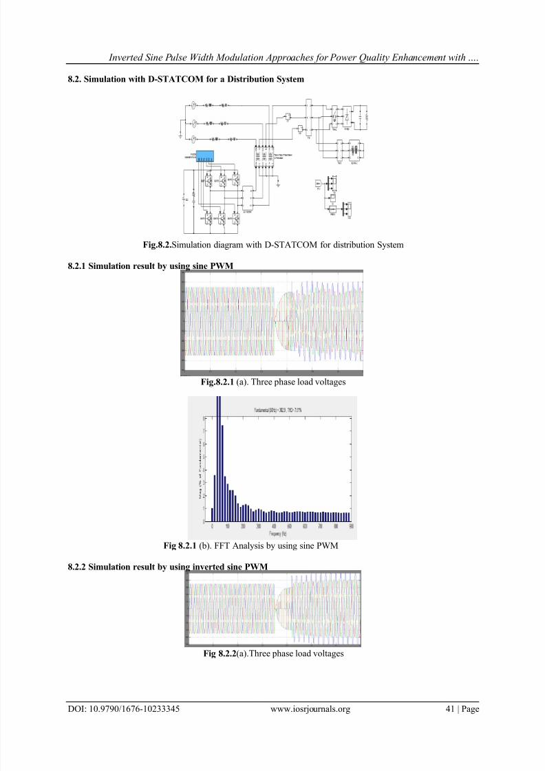
VIII. Simulation Results8.1. Simulation without Compensation for a Distribution System
Fig.8.1 (a) Simulation block diagram without Compensation for distribution system
Fig.8.1 (b) Three phase Load voltages
Fig8.1 (d) FFT Analysis
8/9/2019 Inverted Sine Pulse Width Modulation Approaches for Power Quality Enhancement with Custom Power Devices
http://slidepdf.com/reader/full/inverted-sine-pulse-width-modulation-approaches-for-power-quality-enhancement 9/13

8/9/2019 Inverted Sine Pulse Width Modulation Approaches for Power Quality Enhancement with Custom Power Devices
http://slidepdf.com/reader/full/inverted-sine-pulse-width-modulation-approaches-for-power-quality-enhancement 10/13
Inverted Sine Pulse Width Modulation Approaches for Power Quality Enhancement with ….
DOI: 10.9790/1676-10233345 www.iosrjournals.org 42 | Page
Fig.8.2.2 (b). FFT Analysis by using inverted sine PWM
8.2.3 Simulation result by using Trapezoidal inverted sine PWM
Fig 8.2.3 (a) Three phase load voltages
Fig 8.2.3 (b) FFT Analysis by using trapezoidal inverted sine PWM
8.2.4 Simulation result by using Sawtooth inverted sine PWM
Fig 8.2.4 (a) Three phase load voltages by using sawtooth inverted sine PWM
Fig 8.2.4 (b) FFT Analysis by using sawtooth inverted sine PWM

8/9/2019 Inverted Sine Pulse Width Modulation Approaches for Power Quality Enhancement with Custom Power Devices
http://slidepdf.com/reader/full/inverted-sine-pulse-width-modulation-approaches-for-power-quality-enhancement 11/13
Inverted Sine Pulse Width Modulation Approaches for Power Quality Enhancement with ….
DOI: 10.9790/1676-10233345 www.iosrjournals.org 43 | Page
IX. Simulation Result With DVR9.1 Simulation with DVR for a distribution system
Fig 9.1 Simulation diagram with DVR for distribution system
9.1.1 Simulation result by using sine PWM
Fig 9.1.1 (a) Three phase load voltages
Fig 9.1.1 (b)FFT Analysis
9.1.2 Simulation result by using inverted sine PWM
Fig 9.1.2 (a)Three phase load voltages
8/9/2019 Inverted Sine Pulse Width Modulation Approaches for Power Quality Enhancement with Custom Power Devices
http://slidepdf.com/reader/full/inverted-sine-pulse-width-modulation-approaches-for-power-quality-enhancement 12/13
Inverted Sine Pulse Width Modulation Approaches for Power Quality Enhancement with ….
DOI: 10.9790/1676-10233345 www.iosrjournals.org 44 | Page
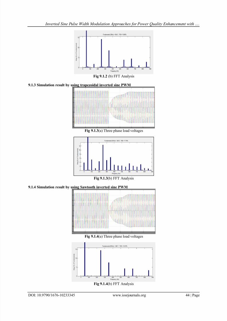
Fig 9.1.2 (b) FFT Analysis
9.1.3 Simulation result by using trapezoidal inverted sine PWM
Fig 9.1.3 (a) Three phase load voltages
Fig 9.1.3 (b) FFT Analysis
9.1.4 Simulation result by using Sawtooth inverted sine PWM
Fig 9.1.4 (a) Three phase load voltages
Fig 9.1.4 (b) FFT Analysis

8/9/2019 Inverted Sine Pulse Width Modulation Approaches for Power Quality Enhancement with Custom Power Devices
http://slidepdf.com/reader/full/inverted-sine-pulse-width-modulation-approaches-for-power-quality-enhancement 13/13
Inverted Sine Pulse Width Modulation Approaches for Power Quality Enhancement with ….
DOI: 10.9790/1676-10233345 www.iosrjournals.org 45 | Page
X. Comparison Of Total Harmonic Distortion For All Modulation Techniques
Fig 10 (b)Bar Chart representation of THD for D-STATCOM and DVR
XI. ConclusionHarmonics produced by the nonlinear load which are connected in distribution system are harmful. In
this paper a novel PWM techniques called inverted sine PWM , trapezoidal inverted sine PWM and sawtoothinverted sine PWM to reduce harmonics and increase power quality using Custom Power Devices areconsidered. By doing FFT analysis it is observed that the Total Harmonic Distortion (THD) of the power systemis reduced after the application of inverted sine PWM and trapezoidal inverted sine PWM techniques in D-STATCOM compared to DVR. The Simulation results show the output voltage across a sensitive load withoutand with D-STATCOM, DVR. The simulation results show very good voltage regulation with lower harmoniccontents with D-STATCOM.
References[1]. N. Hingorani, ―FACTS— Flexible ac transmission systems,‖ in Proc. IEE 5th Int. Conf. AC DC Transmission, London, U.K., 1991,
Conf. Pub.345, pp. 1 – 7.[2]. Olimpo Anaya-Lara and E. Acha, Modeling and Analysis of Custom Power Systems by PSCAD/EMTDC,‖ IEEE Trans. Power
Delivery, vol. 17, No.1, Jan. 2002[3]. A. Ghosh, (2002). ―Power quality enhancementusing custom Power devices,‖ Khuvar Acadamic Publishers.[4]. Seyezhai and B.L.Mathur, ―Performance Evaluation of Inverted Sine PWM Techniques for an Asymmetric Multilevel Inverter‖,
Journal of Theoretical and Applied Information Technology, Vol.2,No. 2, 2009, pp. 91-98.[5]. Rodda Shobha Rani1, B. Jyothi2 VSC Based DSTATCOM & Pulse-width modulation for Power Quality Improvement
International Journal of Engineering Trends and Technology- Volume2Issue2- 2011[6]. S. Esmaeili Jafarabadi, G. B. Gharehpetian,‖ A New ISPWM Switching Technique for THD Reduction in Custom Power Devices‖. [7]. S.Malathy,Dr.R.Ramaprabha‖Trapezoidal inveted sine PWM techniques for fundamental fortification in PV fed multilevel
inverters‖ International Journal of Emerging Technology and Advanced Engineering ,ISSN 2250-2459, Volume 2, Issue 4, April2012.
[8]. B.Shanthi and S.P.Natarajan, Comparative study on various unipolar PWM strategies for single phase five level cascadedinverter ,International Journal of Power Electronics (IJPELEC), Special issue on: Power Converters: Modeling, Simulation,Analysis, Topologies, Secondary issues and Applications, InderScience publication,Switzerland, pp.36-50, 2009 ernational Journalof Emerging Technology and Advanced Engineering ,ISSN 2250-2459, Volume 2, Issue 4, April 2012.
[9]. S.Yuvarajan and Abdollah Khoei, ―A novel PWM for harmonic reduction and its application to ac-dc converters,‖ IETE Journal ofResearch, Vol. 48, No. 2, March-April 2002.
[10]. P. Palanivel, S.S. Dash, ―Analysis of THD and Output Voltage Performance for Cascaded Multilevel Inverter Using Carrier Pulse Widt h Modulation Techniques‖, IET Power Electron, Vol. 4, Issue 8, pp. 951 -958, 2011