invacare fox service manual · via dei pini, 62 ; i - 36016 thiene (vi) italia (: +39 0445 38 00 59...
TRANSCRIPT

Edition: 1577880 Vers. 002 - 13.10.2014
Invacare ® Fox SERVICE MANUAL
SERVICE MANUAL Invacare ® - Fox
2
These instructions contain information about:
Testing work
Repair Instructions
This manual is part of the instructions for use.
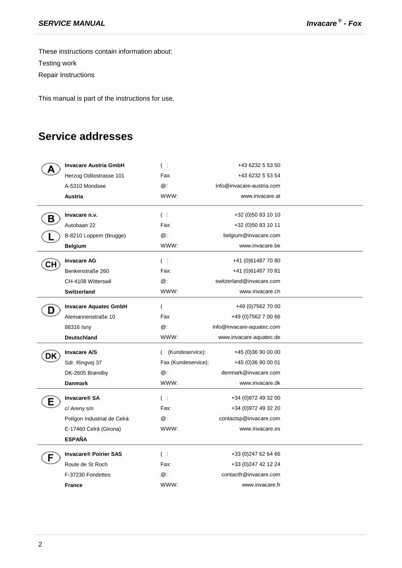
Service addresses
Invacare Austria GmbH
Herzog Odilostrasse 101
A-5310 Mondsee
Austria
(: +43 6232 5 53 50
Fax: +43 6232 5 53 54
WWW: www.invacare.at
Invacare n.v.
Autobaan 22
B-8210 Loppem (Brugge)
Belgium
(: +32 (0)50 83 10 10
Fax: +32 (0)50 83 10 11
WWW: www.invacare.be
Invacare AG
Benkenstraße 260
CH-4108 Witterswil
Switzerland
(: +41 (0)61487 70 80
Fax: +41 (0)61487 70 81
WWW: www.invacare.ch
Invacare Aquatec GmbH
Alemannenstraße 10
88316 Isny
Deutschland
( +49 (0)7562 70 00
Fax +49 (0)7562 7 00 66
WWW: www.invacare-aquatec.de
Invacare A/S
Sdr. Ringvej 37
DK-2605 Brøndby
Danmark
( (Kundeservice): +45 (0)36 90 00 00
Fax (Kundeservice): +45 (0)36 90 00 01
WWW: www.invacare.dk
Invacare® SA
c/ Areny s/n
Polígon Industrial de Celrà
E-17460 Celrà (Girona)
ESPAÑA
(: +34 (0)972 49 32 00
Fax: +34 (0)972 49 32 20
WWW: www.invacare.es
Invacare® Poirier SAS
Route de St Roch
F-37230 Fondettes
France
(: +33 (0)247 62 64 66
Fax: +33 (0)247 42 12 24
WWW: www.invacare.fr

Invacare ® - Fox SERVICE MANUAL
3
Invacare® Ltd
Pencoed Technology Park
Pencoed
Bridgend CF35 5HZ
United Kingdom
( (Customer services): +44 (0)1656 77 62 22
Fax (Customer services): +44 (0)1656 77 62 20
WWW: www.invacare.co.uk
Invacare Mecc San s.r.l.
Via dei Pini, 62
I - 36016 Thiene (VI)
Italia
(: +39 0445 38 00 59
Fax: +39 0445 38 00 34
WWW: www.invacare.it
Invacare Ireland Ltd.
Unit 5 Seatown Business Campus
Seatown Rd, Swords
County Dublin
Ireland
(: +353 18 10 70 84
Fax: +353 18 10 70 85
WWW: www.invacare.ie
Invacare® AS
Grensesvingen 9
Postboks 6230
Etterstad
N-0603 Oslo
Norge
( (Kundeservice): +47 (0)22 57 95 00
Fax (Kundeservice): +47 (0)22 57 95 01
WWW: www.invacare.no
Invacare® B.V.
Celsiusstraat 46
NL-6716 BZ Ede
Nederland
(: +31 (0)318 69 57 57
Fax: +31 (0)318 69 57 58
WWW: www.invacare.nl
Invacare Lda
Rua Estrada Velha, 949
P-4465-784 Leça do Balio
Portugal
(: +351 225 10 59 46
(: +351 225 10 59 47
Fax: +351 225 10 57 39
WWW: www.invacare.pt

SERVICE MANUAL Invacare ® - Fox
4
Återförsäljare:
Invacare® AB
Fagerstagatan 9
S-163 91 Spånga
Sverige
Tillverkare:
Invacare® Deutschland GmbH
Kleiststraße 49
D-32457 Porta Westfalica
Deutschland
( (Kundtjänst): +46 (0)8 761 70 90
Fax (Kundtjänst): +46 (0)8 761 81 08
WWW: www.invacare.se
MÖLNDAL
(: +46 (0)31 86 36 00
Fax: +46 (0)31 86 36 06
LANDSKRONA
(: +46 (0)418 2 85 40
Fax: +46 (0)418 1 80 89
OSKARSHAMN
(: +46 (0)491 1 01 40
Fax: +46 (0)491 1 01 80
Eastern european countries
European Distributor Organisation (EDO)
Kleiststraße 49
D-32457 Porta Westfalica
Deutschland
( +49 (0)5731 75 45 40
Fax +49 (0)5731 75 45 41
WWW: www.invacare.de

Invacare ® - Fox SERVICE MANUAL
5
Contents
Chapter Page
1 Introduction 8
1.1 General information .................................................................................................................. 8
1.2 Notes on shipping ..................................................................................................................... 8
1.3 Definition and representation of information and safety information in this manual ........ 9
1.4 Hazard symbols and symbols used ....................................................................................... 10
1.5 Images in this manual ............................................................................................................. 11
2 Safety and fitting instructions 12
2.1 Before any inspection or repair work .................................................................................... 12
2.2 Personal safety equipment ..................................................................................................... 12
2.3 General safety information and information about fitting / removal .................................. 12
3 Tightening torques 14
4 Layout of components and componentry 15
4.1 Overview ................................................................................................................................... 15
4.2 Overview of the electronic modules ...................................................................................... 16
5 Service plan (1x annually) 17
6 Operational faults 19
6.1 Drive fault diagnosis ............................................................................................................... 19
6.2 Shark Error codes and diagnostic codes .............................................................................. 21
7 Repair work 22
7.1 Covers ....................................................................................................................................... 22
7.1.1 Rear cover .................................................................................................................... 22 7.1.2 Battery cover ................................................................................................................. 23
7.2 Electronic modules.................................................................................................................. 25
7.2.1 Replacing the power module ........................................................................................ 25 7.2.2 Replace remote ............................................................................................................ 27 7.2.3 Drive program selection after component replacement ................................................ 27
7.3 Updating the driving program ................................................................................................ 28
7.4 Batteries ................................................................................................................................... 29
7.4.1 Replacing batteries ....................................................................................................... 29 7.4.2 Installing/removing the battery boxes ........................................................................... 32 7.4.3 Correct handling of damaged batteries ......................................................................... 33
7.5 Resetting circuit breaker......................................................................................................... 34
SERVICE MANUAL Invacare ® - Fox
6
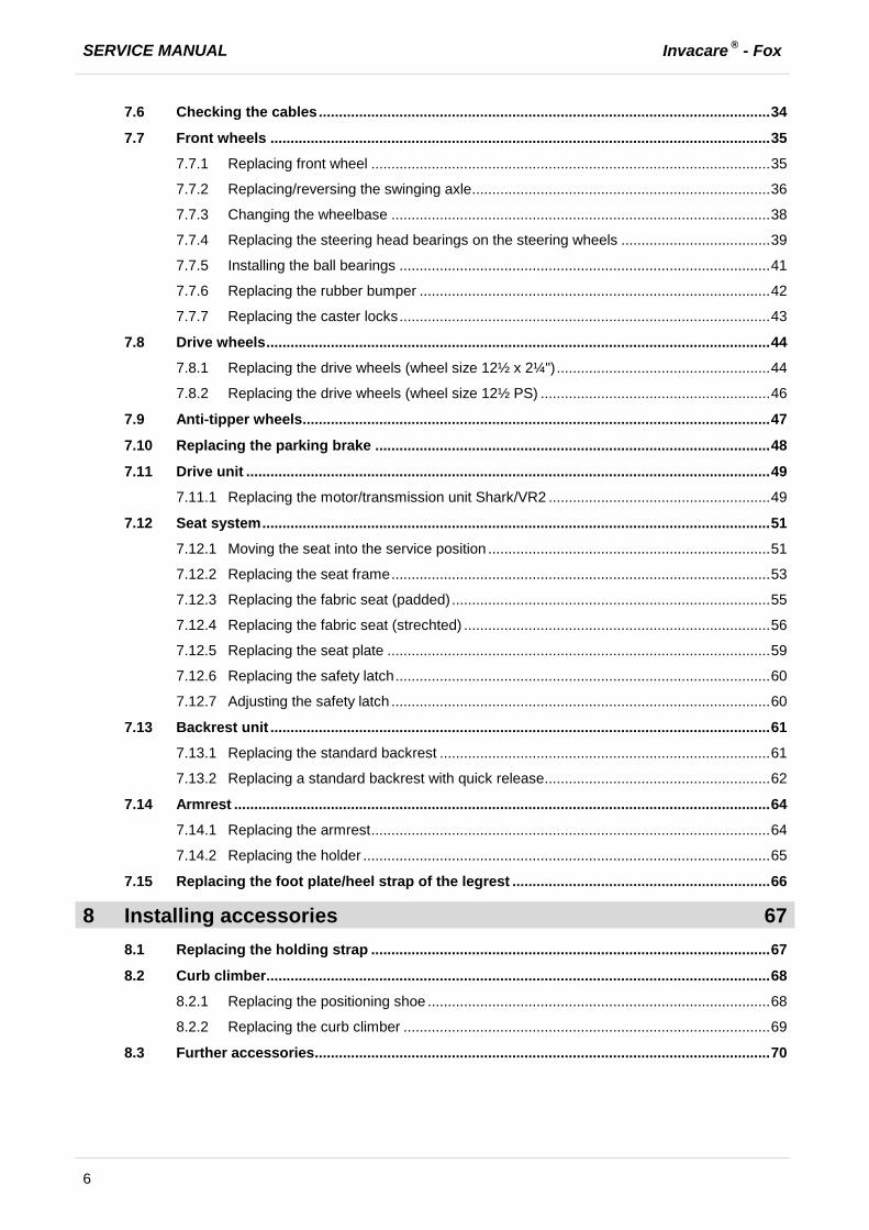
7.6 Checking the cables ................................................................................................................ 34
7.7 Front wheels ............................................................................................................................ 35
7.7.1 Replacing front wheel ................................................................................................... 35 7.7.2 Replacing/reversing the swinging axle .......................................................................... 36 7.7.3 Changing the wheelbase .............................................................................................. 38 7.7.4 Replacing the steering head bearings on the steering wheels ..................................... 39 7.7.5 Installing the ball bearings ............................................................................................ 41 7.7.6 Replacing the rubber bumper ....................................................................................... 42 7.7.7 Replacing the caster locks ............................................................................................ 43
7.8 Drive wheels ............................................................................................................................. 44
7.8.1 Replacing the drive wheels (wheel size 12½ x 2¼") ..................................................... 44 7.8.2 Replacing the drive wheels (wheel size 12½ PS) ......................................................... 46
7.9 Anti-tipper wheels .................................................................................................................... 47
7.10 Replacing the parking brake .................................................................................................. 48
7.11 Drive unit .................................................................................................................................. 49
7.11.1 Replacing the motor/transmission unit Shark/VR2 ....................................................... 49
7.12 Seat system .............................................................................................................................. 51
7.12.1 Moving the seat into the service position ...................................................................... 51 7.12.2 Replacing the seat frame .............................................................................................. 53 7.12.3 Replacing the fabric seat (padded) ............................................................................... 55 7.12.4 Replacing the fabric seat (strechted) ............................................................................ 56 7.12.5 Replacing the seat plate ............................................................................................... 59 7.12.6 Replacing the safety latch ............................................................................................. 60 7.12.7 Adjusting the safety latch .............................................................................................. 60
7.13 Backrest unit ............................................................................................................................ 61
7.13.1 Replacing the standard backrest .................................................................................. 61 7.13.2 Replacing a standard backrest with quick release ........................................................ 62
7.14 Armrest ..................................................................................................................................... 64
7.14.1 Replacing the armrest ................................................................................................... 64 7.14.2 Replacing the holder ..................................................................................................... 65
7.15 Replacing the foot plate/heel strap of the legrest ................................................................ 66
8 Installing accessories 67
8.1 Replacing the holding strap ................................................................................................... 67
8.2 Curb climber ............................................................................................................................. 68
8.2.1 Replacing the positioning shoe ..................................................................................... 68 8.2.2 Replacing the curb climber ........................................................................................... 69
8.3 Further accessories ................................................................................................................. 70

Invacare ® - Fox SERVICE MANUAL
7
9 Adjusting the seating position 71
9.1 Adjusting the lower leg length and seat depth ..................................................................... 72
9.1.1 Adjusting the lower leg length ....................................................................................... 72 9.1.2 Adjusting the seat depth ............................................................................................... 72 9.1.2.1 Adjusting the seat depth via the backrest unit (fabric seat padded) ........................ 73 9.1.2.2 Adjusting the seat depth via the backrest unit (fabric seat strechted) ..................... 74
9.2 Adjusting the seat height ........................................................................................................ 75
9.2.1 Adjusting seat height above centre column .................................................................. 75 9.2.2 Adjusting seat height above seat support ..................................................................... 75
9.3 Adjusting the seat tilt .............................................................................................................. 76
9.4 Adjusting the center of gravity of the seat ............................................................................ 76
SERVICE MANUAL Invacare ® - Fox
8
1 Introduction
1.1 General information
· Service and maintenance work must be carried out taking this service manual into account.
· It is imperative that you observe safety information.
· Information about operation or about general maintenance and care work on the mobility aid should be taken from the operating manual.
· You can find information about ordering spare parts in the spare parts catalogue.
· Only use original Invacare® spare parts. The guarantee will become invalid if other spare parts are used!
· We reserve the right to make any alterations on the grounds of technical improvements.
· The mobility aid may only be maintained and overhauled by qualified personnel.
· The minimum requirement for service technicians is suitable training, such as in the cycle or orthopaedic mechanics fields, or sufficiently long-term job experience. - Experience in the use of electrical measuring equipment (multimeters) is also a requirement. - Special Invacare® training is recommended.
· Alterations to the mobility aid which occur as a result of incorrectly or improperly executed maintenance or overhaul work lead to the exclusion of all liability on the side of INVACARE.
· If you have any problems or questions please contact Invacare® Service.
1.2 Notes on shipping
· If the mobility aid has to be shipped back to the manufacturer for major repairs, you should always use the original packaging for transport.
· Please attach a precise description of the fault.

Invacare ® - Fox SERVICE MANUAL
9
1.3 Definition and representation of information and safety information in this manual Different types of information and signal words are used throughout this manual.
HAZARD!
The signal word "HAZARD!" refers to immediate hazards. · The following lines in italics refer to actions which serve to avoid such hazards.
WARNING!
The signal word "WARNING!" refers to possibly-occurring hazards which can lead to death or serious injuries if they are not avoided. · The following lines in italics refer to actions which serve to avoid such hazards.
ATTENTION!
The signal word " ATTENTION!" refers to possibly-occurring hazards which can lead to minor injuries and/or material damage if they are not avoided. · The following lines in italics refer to actions which serve to avoid such hazards.
CAUTION!
The signal word "CAUTION!" refers to hazards which could lead to material damage if they are not avoided. · The following lines in italics refer to actions which serve to avoid such hazards.
Note
The signal word "Note" is used to denote general information which simplifies the handling of your product and refers to special functions.
SERVICE MANUAL Invacare ® - Fox
10
1.4 Hazard symbols and symbols used Different types of hazard symbols and symbols are used throughout this manual.
General hazards
This symbol warns you of general hazards! · Always follow the instructions to avoid injury to the user or damage to the product!
BURN HAZARD!
This symbol warns you of the danger of chemical burns, for example due to the discharge of battery acids! · Always follow the instructions to avoid injury to the user or damage to the product!
DANGER OF CRUSHING!
This symbol warns you of crushing hazards due to inattentive working with heavy components. · Always follow the instructions to avoid injury to the user or damage to the product!
EXPLOSION HAZARD!
This symbol warns you of an explosion hazard, which can be caused by excessive tyre pressure in a pneumatic tyre. · Always follow the instructions to avoid injury to the user or damage to the product!
Wear safety shoes
The symbol refers to the requirement for wearing safety shoes. · Wear standardised safety shoes during all work.
Wear eye protection
This symbol refers to the requirement for wearing eye protection, for example when working with batteries. · Wear eye protection when this symbol is shown.
Wear safety gloves
This symbol refers to the requirement for wearing safety gloves, for example when working with batteries. · Wear safety gloves when this symbol is shown.
Note
This symbol identifies general information which is intended to simplify working with your product and which refers to special functions.
Requirements:
· This symbol identifies a list of various tools, components and items which you will need in order to carry out certain work. Please do not attempt to carry out the work if you do not have the listed tools available.
Always dispose used or damaged batteries correctly The symbol refers to information for the correct disposal of used or damaged batteries.

Invacare ® - Fox SERVICE MANUAL
11
1.5 Images in this manual The detailed images in this manual are given digits to identify various components. Component numbers in text and operational instructions always relate to the image directly above.

SERVICE MANUAL Invacare ® - Fox
12
2 Safety and fitting instructions These safety instructions are intended to prevent accidents at work, and it is imperative that they are observed.
2.1 Before any inspection or repair work
· Read and observe this repair manual and the associated operating manual!
· Observe the minimum requirements for carrying out the work (see chapter entitled " General information)!
2.2 Personal safety equipment
Safety shoes
The mobility device, and some of its components, are very heavy. These parts can result in injuries to the feet if they are allowed to drop. · Wear standardised safety shoes during all work.
Eye protection
It is possible that battery acid can be discharged when working on defective batteries or when handling batteries improperly. · Always wear eye protection when working on any defective or possibly defective batteries.
Safety gloves
It is possible that battery acid can be discharged when working on defective batteries or when handling batteries improperly. · Always wear acid-proof safety gloves when working on any defective or possibly defective
batteries.
2.3 General safety information and information about fitting / removal
WARNING: Danger of crushing!
Various components such as the drive unit, batteries, seat etc are very heavy. This results in injury hazards to your hands! · Please note the high weight of some components! This applies especially to the removal of
drive units, batteries and the seat.
WARNING!
Injury hazard if the vehicle starts moving unintentionally during repair work! · Switch the power supply off (ON/OFF key)! · Engage the drive! · Before jacking up, secure the vehicle by using chocks to block the wheels.
ATTENTION!
Fire and burn hazard due to electrical short-circuit! · The mobility device must be completely switched off before removal of voltage-carrying
components! To do this, remove the batteries. · Avoid short-circuiting the contacts when carrying out measurements on voltage-carrying
components!
Invacare ® - Fox SERVICE MANUAL
13
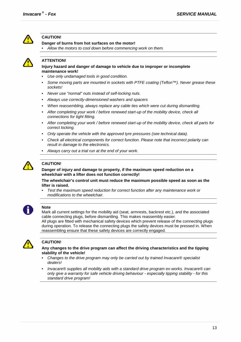
CAUTION!
Danger of burns from hot surfaces on the motor! · Allow the motors to cool down before commencing work on them.
ATTENTION!
Injury hazard and danger of damage to vehicle due to improper or incomplete maintenance work! · Use only undamaged tools in good condition. · Some moving parts are mounted in sockets with PTFE coating (Teflon™). Never grease these
sockets! · Never use "normal" nuts instead of self-locking nuts. · Always use correctly-dimensioned washers and spacers · When reassembling, always replace any cable ties which were cut during dismantling. · After completing your work / before renewed start-up of the mobility device, check all
connections for tight fitting. · After completing your work / before renewed start-up of the mobility device, check all parts for
correct locking. · Only operate the vehicle with the approved tyre pressures (see technical data). · Check all electrical components for correct function. Please note that incorrect polarity can
result in damage to the electronics. · Always carry out a trial run at the end of your work.
CAUTION!
Danger of injury and damage to property, if the maximum speed reduction on a wheelchair with a lifter does not function correctly! The wheelchair’s control unit must reduce the maximum possible speed as soon as the lifter is raised. · Test the maximum speed reduction for correct function after any maintenance work or
modifications to the wheelchair.
Note
Mark all current settings for the mobility aid (seat, armrests, backrest etc.), and the associated cable connecting plugs, before dismantling. This makes reassembly easier. All plugs are fitted with mechanical safety devices which prevent release of the connecting plugs during operation. To release the connecting plugs the safety devices must be pressed in. When reassembling ensure that these safety devices are correctly engaged.
CAUTION!
Any changes to the drive program can affect the driving characteristics and the tipping stability of the vehicle! · Changes to the drive program may only be carried out by trained Invacare® specialist
dealers! · Invacare® supplies all mobility aids with a standard drive program ex-works. Invacare® can
only give a warranty for safe vehicle driving behaviour - especially tipping stability - for this standard drive program!
SERVICE MANUAL Invacare ® - Fox
14
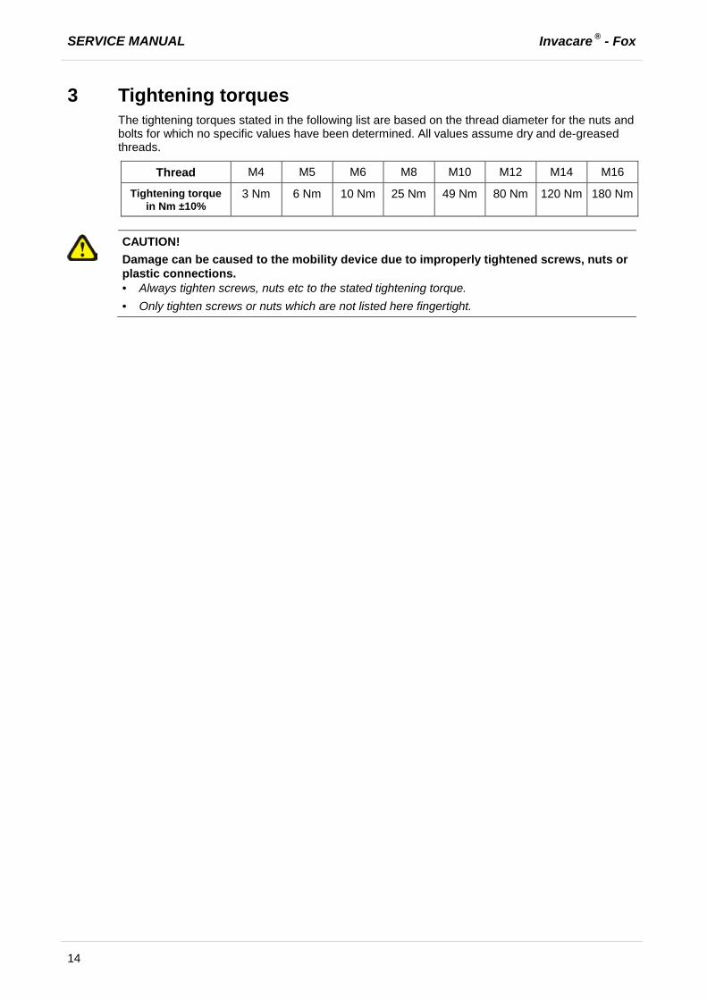
3 Tightening torques The tightening torques stated in the following list are based on the thread diameter for the nuts and bolts for which no specific values have been determined. All values assume dry and de-greased threads.
Thread M4 M5 M6 M8 M10 M12 M14 M16
Tightening torque in Nm ±10%
3 Nm 6 Nm 10 Nm 25 Nm 49 Nm 80 Nm 120 Nm 180 Nm
CAUTION!
Damage can be caused to the mobility device due to improperly tightened screws, nuts or plastic connections. · Always tighten screws, nuts etc to the stated tightening torque. · Only tighten screws or nuts which are not listed here fingertight.

Invacare ® - Fox SERVICE MANUAL
15
4 Layout of components and componentry
4.1 Overview
Under the rear cover:
1) Power module 2) Drive unit The electronic modules used are described in chapter 4.2.
Under the seat:
1) Parking brake 2) Battery boxes 3) Saferty latches for the seat
Special features:
1) Scissor system, please refer to user manual.
2) Swinging axle, please refer to chapter 7.7.2.
SERVICE MANUAL Invacare ® - Fox
16
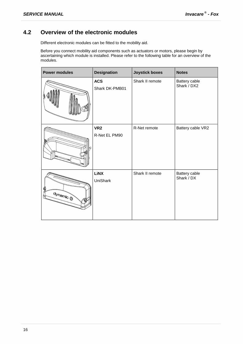
4.2 Overview of the electronic modules Different electronic modules can be fitted to the mobility aid.
Before you connect mobility aid components such as actuators or motors, please begin by ascertaining which module is installed. Please refer to the following table for an overview of the modules.
Power modules Designation Joystick boxes Notes
ACS
Shark DK-PMB01
Shark II remote Battery cable Shark / DX2
VR2
R-Net EL PM90
R-Net remote Battery cable VR2
LiNX
UniShark
Shark II remote Battery cable Shark / DX
Invacare ® - Fox SERVICE MANUAL
17
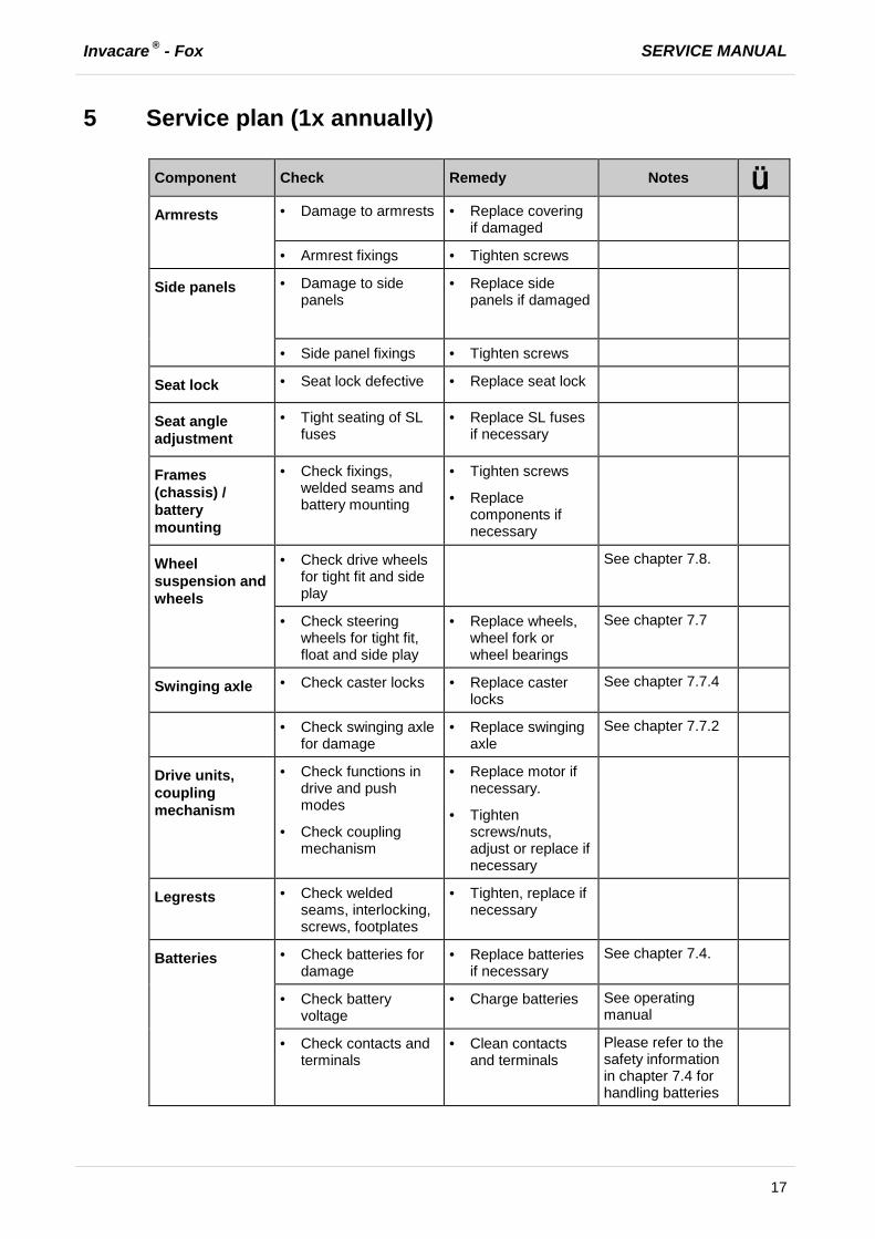
5 Service plan (1x annually)
Component Check Remedy Notes ü Armrests · Damage to armrests · Replace covering
if damaged
· Armrest fixings · Tighten screws
Side panels · Damage to side panels
· Replace side panels if damaged
· Side panel fixings · Tighten screws
Seat lock · Seat lock defective · Replace seat lock
Seat angle adjustment
· Tight seating of SL fuses
· Replace SL fuses if necessary
Frames (chassis) / battery mounting
· Check fixings, welded seams and battery mounting
· Tighten screws
· Replace components if necessary
Wheel suspension and wheels
· Check drive wheels for tight fit and side play
See chapter 7.8.
· Check steering wheels for tight fit, float and side play
· Replace wheels, wheel fork or wheel bearings
See chapter 7.7
Swinging axle · Check caster locks · Replace caster locks
See chapter 7.7.4
· Check swinging axle for damage
· Replace swinging axle
See chapter 7.7.2
Drive units, coupling mechanism
· Check functions in drive and push modes
· Check coupling mechanism
· Replace motor if necessary.
· Tighten screws/nuts, adjust or replace if necessary
Legrests · Check welded seams, interlocking, screws, footplates
· Tighten, replace if necessary
Batteries · Check batteries for damage
· Replace batteries if necessary
See chapter 7.4.
· Check battery voltage
· Charge batteries See operating manual
· Check contacts and terminals
· Clean contacts and terminals
Please refer to the safety information in chapter 7.4 for handling batteries

SERVICE MANUAL Invacare ® - Fox
18
Component Check Remedy Notes ü Remote / electronic module
· Remote, status display blinking
· Evaluate error/blink code
· Fixings · Tighten fixings, replace if necessary
· Cables and connecting plugs
· Tighten cables and connecting plugs, replace if necessary
· Drive lever function · Replace drive lever if necessary
· Replace remote if necessary
· Power supply · Tighten cables and connecting plugs, replace if necessary
Drive program · Check drive electronics program version
· Update software if newer version available.
See chapter 7.3.
Invacare ® - Fox SERVICE MANUAL
19
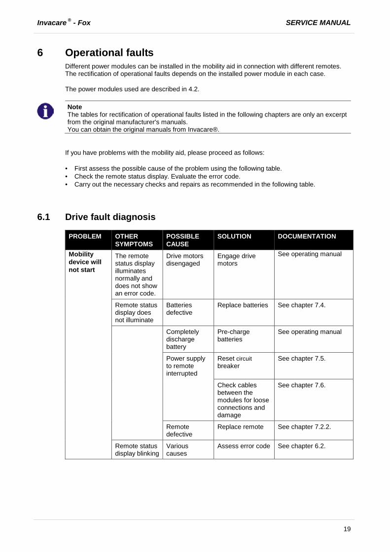
6 Operational faults Different power modules can be installed in the mobility aid in connection with different remotes. The rectification of operational faults depends on the installed power module in each case.
The power modules used are described in 4.2.
Note
The tables for rectification of operational faults listed in the following chapters are only an excerpt from the original manufacturer's manuals. You can obtain the original manuals from Invacare®.
If you have problems with the mobility aid, please proceed as follows:
· First assess the possible cause of the problem using the following table. · Check the remote status display. Evaluate the error code. · Carry out the necessary checks and repairs as recommended in the following table.
6.1 Drive fault diagnosis
PROBLEM OTHER SYMPTOMS
POSSIBLE CAUSE
SOLUTION DOCUMENTATION
Mobility device will not start
The remote status display illuminates normally and does not show an error code.
Drive motors disengaged
Engage drive motors
See operating manual
Remote status display does not illuminate
Batteries defective
Replace batteries See chapter 7.4.
Completely discharge battery
Pre-charge batteries
See operating manual
Power supply to remote interrupted
Reset circuit breaker
See chapter 7.5.
Check cables between the modules for loose connections and damage
See chapter 7.6.
Remote defective
Replace remote See chapter 7.2.2.
Remote status display blinking
Various causes
Assess error code See chapter 6.2.
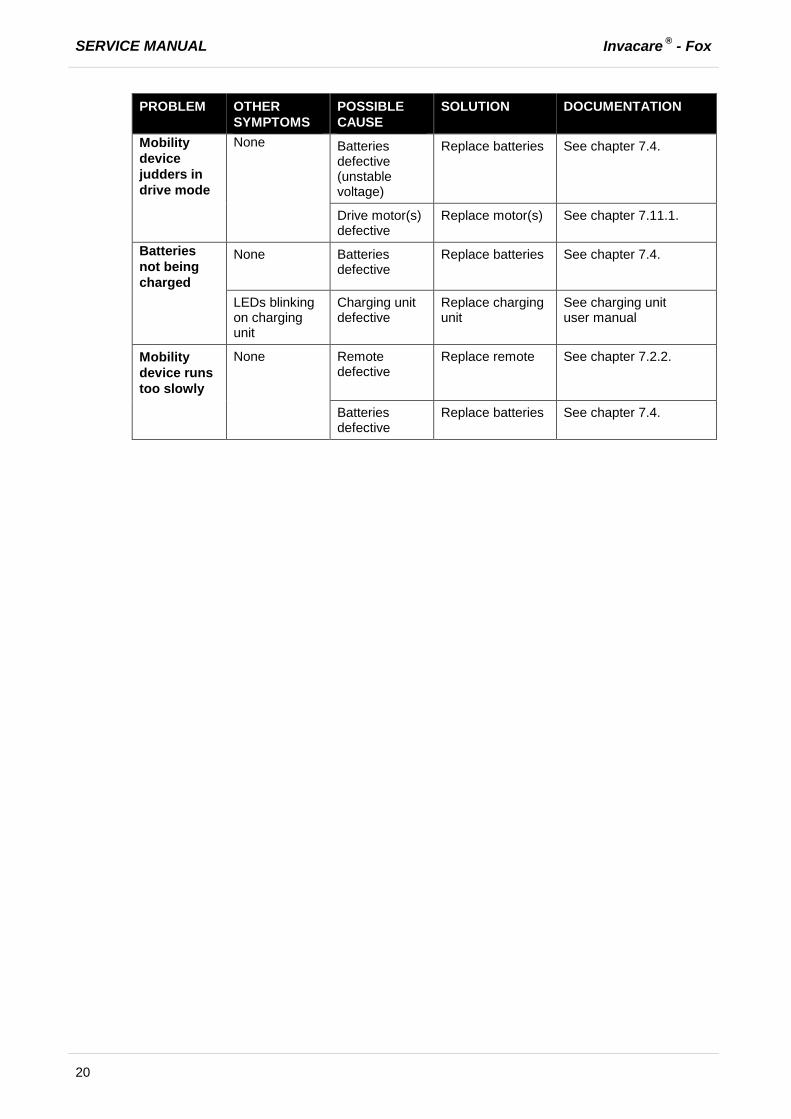
SERVICE MANUAL Invacare ® - Fox
20
PROBLEM OTHER SYMPTOMS
POSSIBLE CAUSE
SOLUTION DOCUMENTATION
Mobility device judders in drive mode
None Batteries defective (unstable voltage)
Replace batteries See chapter 7.4.
Drive motor(s) defective
Replace motor(s) See chapter 7.11.1.
Batteries not being charged
None Batteries defective
Replace batteries See chapter 7.4.
LEDs blinking on charging unit
Charging unit defective
Replace charging unit
See charging unit user manual
Mobility device runs too slowly
None Remote defective
Replace remote See chapter 7.2.2.
Batteries defective
Replace batteries See chapter 7.4.

Invacare ® - Fox SERVICE MANUAL
21
6.2 Shark Error codes and diagnostic codes The drive electronics can automatically rectify some faults. In this case the status display will stop blinking. Switch the remote on and off again several times. Wait around 5 seconds each time before switching the remote on again. If this does not rectify the fault, determine the cause using the following link codes:
Blink Code
Meaning Solution Documentation
1 Operating error Set drive lever to neutral central position (just release drive lever) and switch on again
2 Battery error Check battery and mains cable See chapter 7.6
Charge batteries. If you switch the mobility device off for a few minutes, the batteries can often charge themselves up enough to enable a short journey. You should, however, only use this solution in emergency situations because it results in excessive battery discharging.
See user manual
Replace batteries See chapter 7.4.1.
3 Fault on left-hand motor (M2)
Check motor cable and connecting plug.
Check motor.
See chapters 7.6 and 7.11.1
4 Fault on right-hand motor (M1)
Check motor cable and connecting plug.
Check motor.
See chapters 7.6 and 7.11.1
5 Fault at left-hand (M2) motor brake
Check cable and plug. See chapter 7.6.
6 Fault right-hand (M1) motor brake
Check cable and plug. See chapter 7.6.
7 Error in Shark remote
Check bus cable in remote and connecting plug.
Replace remote.
See chapter 7.6. and 7.2.2
8 Error in Shark power module
Check all the cables and plugs in the Shark system.
Replace electronics module
See chapters 7.6 and 7.2.1
9 Communication error in Shark system
Check all cables and connecting plugs in the Shark system.
Replace remote.
See chapters 7.6 and 7.2.2
10 Unknown error Check all cables and connecting plugs. See chapter 7.6.
11 Incompatible remote
The wrong remote has been connected. Ensure that electronic module code and the remote code match.
See chapter 7.2.2 and chapter 7.2.1.

SERVICE MANUAL Invacare ® - Fox
22
7 Repair work
7.1 Covers
7.1.1 Rear cover
Requirements:
· 3 mm Allen key · oblique pliers · cable binder
Removing the rear cover:
· Loosen the cable tie from the bus cable in the indentation (1) right or left.
· Loosen and remove the two Allen screws (2) including washer on the left and right of the rear cover (3).
· Pull the rear cover carefully forwards away from the chassis.
Assembling the rear cover:
· Push the rear cover over the chassis.
Ensure that the bus cable is located in the indentation (1).
· Fasten the Allen screws (2) including washer.
· Tighten the Allen screws to 3 Nm +/-1 N.
· Fix the bus cable using a cable tie.
Invacare ® - Fox SERVICE MANUAL
23
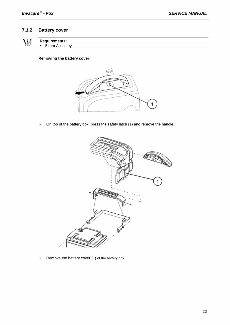
7.1.2 Battery cover
Requirements:
· 5 mm Allen key
Removing the battery cover:
· On top of the battery box, press the safety latch (1) and remove the handle.
· Remove the battery cover (1) of the battery box.

SERVICE MANUAL Invacare ® - Fox
24
Assembling the battery cover:
· Refit the battery cover.
· Refit the handle to the cover. Ensure that the safety interlock engages.
· Insert the battery pack.
Invacare ® - Fox SERVICE MANUAL
25
7.2 Electronic modules
7.2.1 Replacing the power module
Note
When replacing the power module in connection with a remote, please take the final selection of the drive program into account as described in chapter 7.2.3.
Different power modules in connection with different remotes can be fitted to the mobility aid. The possible power modules are described in chapter 4.2.
CAUTION!
Any changes to the drive program can affect the driving characteristics and the tipping stability of the mobility aid! · Changes to the drive program may only be carried out by trained Invacare® specialist
dealers! · Invacare® can only give a warranty for safe mobility aid driving behaviour - especially tipping
stability - for unaltered standard drive programs!
Note
All power modules are delivered with a standard drive program. If you have made any customer-specific modifications to the drive program, these must be adapted after the installation of the new power module.
Requirements:
· 8 mm socket spanner · To adapt the drive program:
programming software or hand programming device and system installation manual, available from Invacare®.
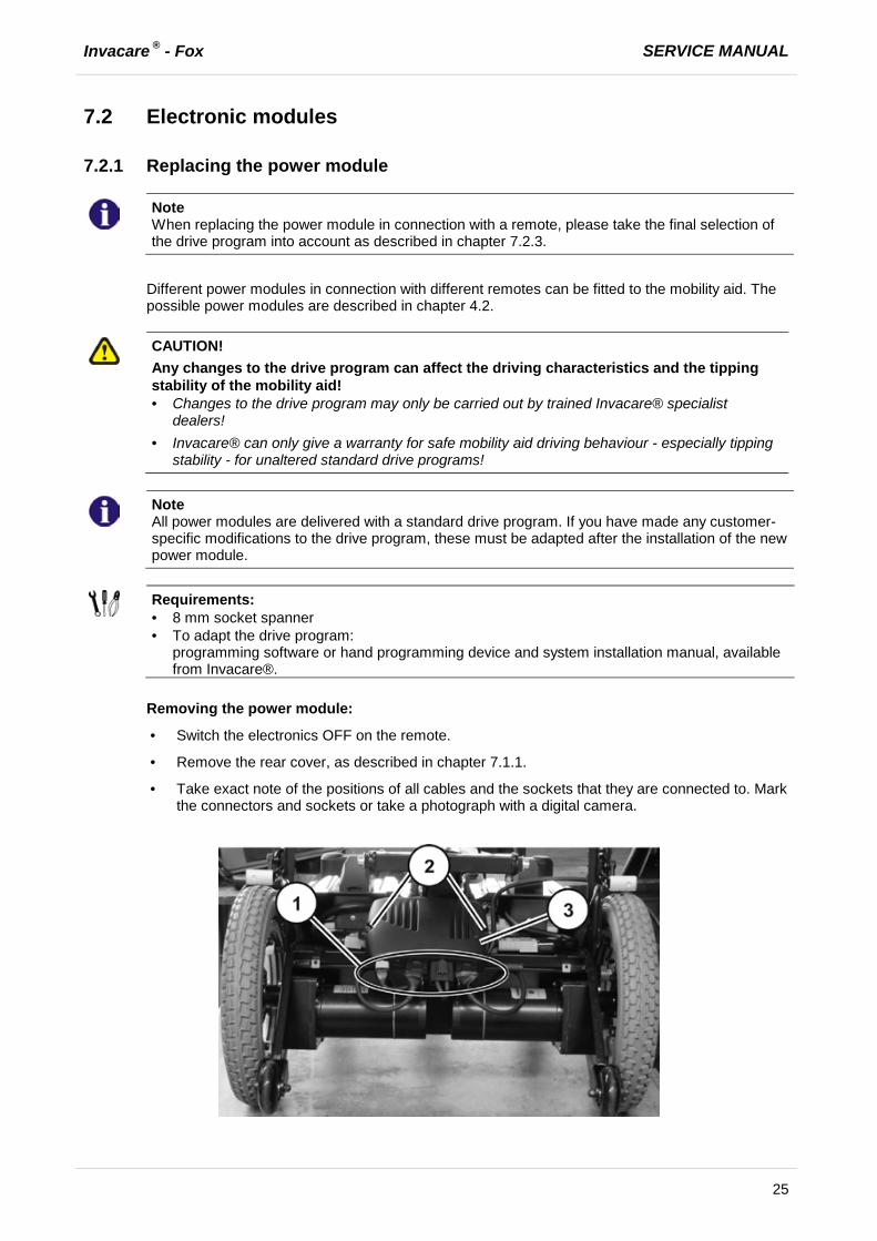
Removing the power module:
· Switch the electronics OFF on the remote.
· Remove the rear cover, as described in chapter 7.1.1.
· Take exact note of the positions of all cables and the sockets that they are connected to. Mark the connectors and sockets or take a photograph with a digital camera.

SERVICE MANUAL Invacare ® - Fox
26
· Disconnect the plugs (1) from the power module (3).
· Use the 8 mm socket wrench to loosen both nuts (2).
· Pull the power module towards the rear and off of the guides.
· Replace the power module.
Installing the power module:
· Assemble the parts in reverse order.
· Reconnect all cable connectors to their former positions.
· Plug all free slots with a suitable rubber stopper.
· Select the driving program, as described in chapter 7.2.3.
· Update the driving program if a new software version is available, as described in chapter 7.3.
· Modify the driving program using the programming software as needed.
· The last step is to test all functions of the vehicle.
Invacare ® - Fox SERVICE MANUAL
27
7.2.2 Replace remote
Note
Replacing the remote is very easy and is not described in detail. However, when replacing a remote in connection with the power module, please take the final selection of the drive program into account as described in chapter 7.2.3.
7.2.3 Drive program selection after component replacement
The drive program is saved in the remote and in the power module. If one of these two components is replaced, the system must be told which of the components has not been replaced so that it knows which contains the current controller profile.
Note
The system allows normal usage of the mobility aid after component replacement only if the profile is selected afterwards.

SERVICE MANUAL Invacare ® - Fox
28
7.3 Updating the driving program The driving programs for electric wheelchairs are continually updated and improved by Invacare®. For this reason, you should check whether the version number is still up to date each time a wheelchair comes in for repairs, and also during regular inspections.
If a newer version is available, the driving program must be updated. The procedure for updating the driving program is described in the user manual of the Wizard software.
Note
The electronic system is supplied with a standard drive program. If the driving program has been customised, you have to perform this customisation again, after installing the new driving program. This also applies to the customer-specific options of the seat setting for ACS 2 remotes, which are activated ex works.
WARNING: Every alteration to the drive program can influence vehicle handling and the
tipping stability of the wheelchair! · Alterations to the drive program must only be carried out by trained Invacare®-dealers! · Invacare® can only assume a warranty for the safe vehicle handling of the wheelchair – in
particular tipping stability - for unaltered standard drive programs!
Pre-requisites:
· Dynamic® Wizard software · User manual for the Wizard software · For further information on other requirements - such as the minimum system configuration of
the PC to be used for programming, necessary programming cables - see the user manual of the Wizard software. You find the latest version of the user manual in the download area on http://www.dynamiccontrols.com/.
Note
When an electrical adjustment option is retrofitted, such as electrical legrests, then this option needs to be activated in the driving program as well if you have an ACS 2 remote. For more information, refer to the user manual of the Wizard software and the installation instructions for the electronic modules

Invacare ® - Fox SERVICE MANUAL
29
7.4 Batteries
7.4.1 Replacing batteries
ATTENTION:
Injury hazard and possible material damages if batteries are handled improperly! · The installation of new batteries may only be carried out by authorised specialists. · Observe the warning information on the batteries. · Only use battery versions stated in the specifications.
ATTENTION:
Fire and burns hazard if battery terminal is bypassed! · Please take great care to ensure that the battery terminals are never short-circuited with tools
or mechanical mobility device parts! · Ensure that the battery terminal caps have been replaced if you are not working on the battery
terminals.
ATTENTION: Danger of crushing!
The batteries are extremely heavy. This results in injury hazards to your hands. · Bear in mind that the batteries are sometimes very heavy! · Please handle the batteries with care.
WARNING: BURN HAZARD! Injury hazard due to discharged acid. · Always wear acid-proof protective gloves when handling batteries. · Always wear protective goggles when handling batteries.
What to do if acid is discharged: · Always take clothing which has been soiled by or dipped in acid off immediately! · Rinse any areas of your skin which has come into contact with battery acid off immediately
with plenty of water!
If contact with eyes is made: · Rinse the affected eye under running water for several minutes! You should also consult an
eye specialist immediately afterwards!
Requirements:
· 5 mm Allen key · 10 mm open-ended spanner · depending on the battery type additionally:
- 10 mm open-ended spanner (32 Ah and 50 Ah battery) - 11 mm open-ended spanner (40 Ah battery)
SERVICE MANUAL Invacare ® - Fox
30
Uninstalling the batteries:
· Switch the electronics OFF on the remote.
· Bring the seat into the service position, as described in chapter 7.12.1.
· Remove the battery boxes, as described in chapter 7.4.2.
· Remove the the handle and cover (1) of the battery box, as described in chapter 7.12.1.
· Loosen and remove the Allen screw (4), including washer (2) and nut (1) with a 5 mm Allen key on both sides of the battery (2).
· Disconnect the cable harness from the battery by removing the pole screws and nuts (A) with a
10 mm open-end wrench.
Invacare ® - Fox SERVICE MANUAL
31
· Remove the mounting bracket (1) and (3) together with the cable harness from the battery (2).
· Repeat the previous steps for the other battery.
Installing the batteries:
· Set the new battery (2) on the plate of the mounting bracket (1).
· Reinstall the mounting bracket and secure with the screws and nuts.

SERVICE MANUAL Invacare ® - Fox
32
· Connect the cable harness to the battery.
Note
(-) RED Cable (A) to the batterie terminal (-) (+) BLUE Cable (B) o the batterie terminal (+).
· Reinstall the cover of the battery box, as described in chapter 7.1.2.
· Reinstall the the batterie box, as described in chapter 7.4.2.
· Place the seat vertically onto its holder again.
· Fold the seat forward.
· Make sure that the safety latches engage on the center post.
· Check all functions of the vehicle and go for a test drive.
7.4.2 Installing/removing the battery boxes
The installation of the battery boxes in the vehicle is described in the user manual.

Invacare ® - Fox SERVICE MANUAL
33
7.4.3 Correct handling of damaged batteries
WARNING: BURN HAZARD! Injury hazard due to discharged acid. · Always wear acid-proof protective gloves when handling batteries. · Always wear protective goggles when handling batteries.
What to do if acid is discharged: · Always take clothing which has been soiled by or dipped in acid off immediately! · Rinse any areas of your skin which has come into contact with battery acid off immediately
with plenty of water!
If contact with eyes is made: · Rinse the affected eye under running water for several minutes! You should also consult an
eye specialist immediately afterwards!
Requirements:
· protective goggles
· acid-proof gloves
· acid-proof transport container
· If handling damaged batteries, always wear suitable protective clothing.
· Always deposit damaged batteries in suitable acid-proof containers immediately after removal.
· Only transport damaged batteries in suitable acid-proof containers.
· Always wash any objects which were contacted by acid in plenty of fresh water.
Always dispose of used or damaged batteries correctly Used and damaged batteries will be taken back by your medical equipment supplier or Invacare®.

SERVICE MANUAL Invacare ® - Fox
34
7.5 Resetting circuit breaker
If the mobility device cannot be switched on, check whether the safety cutout has triggered. The safety cutout is reset by pressing the knob inwards. See user manual.
7.6 Checking the cables
· Switch the electronics OFF on the remote.
· Remove the rear cover, as described in chapter 7.1.1.
· Check all cables for visible damage, crushing points or abrasion points.
· Replace damaged cables.
· Pull on each plug carefully. The plug must not come out of its socket when pulled on lightly.
· If a plug is loose, apply slight pressure to push the plug into the socket. The plug must snap in place securely.
· Check that the plug is firmly attached to its socket.
· Remove the batteries, as described in chapter 7.4.
· Check the battery cables for visible damage, crushing points or abrasion points.
· Replace damaged cables.
· Assemble all parts again in reverse order.
· The last step is to test all functions of the vehicle.

Invacare ® - Fox SERVICE MANUAL
35
7.7 Front wheels
7.7.1 Replacing front wheel
ATTENTION: Danger of crushing to the hands and feet by the weight of the wheelchair! · Pay attention to the hand and feet. · Use proper lifting techniques.
Danger of injury due to uncontrolled movement of the wheelchair! · Switch the vehicle's power system off (ON-/OFF key). · Engage the drive motors. · Secure the vehicle against rolling away by placing wedges under the wheels.
Requirements:
· 5 mm Allen key · 13 mm open-ended spanner · oblong wooden block (approx.14 x 14x 30 cm)
Removing the wheel:
· Prop up the wheelchair on multiple wooden blocks. Use proper lifting techniques.
· Counter the axle nut (3) using an open-end wrench.
· Loosen and remove the Allen screw (5). Pay attention to the washer (4).
· Pull the axle out of the front fork (2).
· Pull the wheel (1) out of the front fork.
SERVICE MANUAL Invacare ® - Fox
36
Refitting the wheel:
· Refit the parts in reverse order.
· When installing the wheel, pay attention to the correct direction of rotation.
7.7.2 Replacing/reversing the swinging axle
The swinging axle can be rotated to change the wheelbase. Fitting the swinging axle facing: Figure (A) long wheelbase Figure (B) short wheelbase
If you change the wheelbase, the centre column on the chassis (see chapter 7.7.3) must be adapted accordingly.
ATTENTION: Danger of crushing to the hands and feet by the weight of the wheelchair! · Pay attention to the hand and feet. · Use proper lifting techniques.
Danger of injury due to uncontrolled movement of the wheelchair! · Switch the vehicle's power system off (ON-/OFF key). · Engage the drive motors. · Secure the vehicle against rolling away by placing wedges under the wheels.
Requirements:
· 10 mm Allen key · wooden block (approx.14 x 14x 30 cm for propping up vehicle) · medium strength threadlocker, such as OmniFit 100M
· Remove the legrests.
· Place a wooden block approximately 14 cm high under the curb climber so that the swinging axle can hang free. Use proper lifting techniques.
Invacare ® - Fox SERVICE MANUAL
37
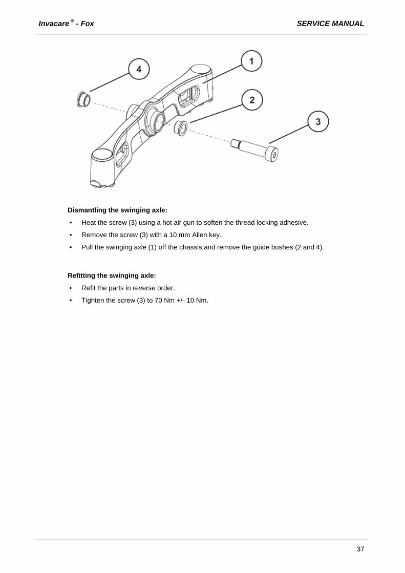
Dismantling the swinging axle:
· Heat the screw (3) using a hot air gun to soften the thread locking adhesive.
· Remove the screw (3) with a 10 mm Allen key.
· Pull the swinging axle (1) off the chassis and remove the guide bushes (2 and 4).
Refitting the swinging axle:
· Refit the parts in reverse order.
· Tighten the screw (3) to 70 Nm +/- 10 Nm.

SERVICE MANUAL Invacare ® - Fox
38
7.7.3 Changing the wheelbase
Requirements:
· 5 mm Allen key · 10 mm socket spanner
· Remove the seat, as described in chapter 7.12.1.
· Loosen and remove the screw and nut (3).
· Adjust the center column (see illustrations).
Long wheelbase
Adjustment of centre column (1) on chassis -> The scale (2) is at the front.
Short wheelbase
Rotating the centre column: Adjustment of centre column (1) on chassis -> The scale (2) is at the back
Note
Changing the wheelbase influences the seat depth and the centre of gravity (chapter 9.4). You may need to adjust the seat depth to meet your requirements. Please refer to chapter 9.1.2.
· Refit the parts in reverse order.
· Check all functions of the vehicle and go for a test drive.

Invacare ® - Fox SERVICE MANUAL
39
7.7.4 Replacing the steering head bearings on the steering wheels
ATTENTION: Danger of crushing to the hands and feet by the weight of the wheelchair! · Pay attention to the hand and feet. · Use proper lifting techniques.
Danger of injury due to uncontrolled movement of the wheelchair! · Switch the vehicle's power system off (ON-/OFF key). · Engage the drive motors. · Secure the vehicle against rolling away by placing wedges under the wheels.
CAUTION!
Incorrect reassembly can damage the bearings and cause the steering wheels to fall out! The single-row angular ball bearing rings are not identical on both sides! There is only one correct way to insert them! · Follow the assembly instructions precisely!
Requirements:
· Phillips screwdriver, size 2 · Phillips screwdriver, 19 mm (caster locks) · Torque wrench · large screwdriver, flat · wooden block (approx.12 x 12x 30 cm for propping up vehicle)
Note
When disassembling, take care of small parts such as screws and washers. Put all small parts down so that they can be reassembled in the right sequence.
· Remove the legrests.
· Secure the vehicle against rolling away.
· Place a wooden block approximately 14 cm high under the curb climber so that the swinging axle is hanging free or dismantle the swinging axle as described in chapter 7.7.2 and secure the swinging axle with a vice.

SERVICE MANUAL Invacare ® - Fox
40
Dismantling the steering head bearings:
· Release the caster locks (5) for the front wheels on the swinging axle (1).
· Remove the front wheels, as described in chapter 7.1.1.
· Use a screwdriver to remove the plastic cap (8).
· Loosen and remove the screws (3) with a 19 mm Phillips screwdriver and remove the locking plate (4).
· Remove the caster lock (5) and the ball bearings (6) and (7).
· Replace all steering head bearings.

Invacare ® - Fox SERVICE MANUAL
41
Refitting the steering head bearings: · Assemble the parts in reverse order.
Note
Ensure that the bearings are inserted precisely as described in chapter 7.7.5. Ensure that the correct caster locks (5) are inserted (left-hand and right-hand sides have different locks). Ensure that the sprung thrust pieces (2) are seated precisely in the securing seat (4) when reassembling.
· Refit the bolts (3) with a medium-strength screw securing system (such as OmniFit 100 M).
· Refit the swinging axle as described in chapter 7.7.2.
· Installing the front wheels, as described in chapter 7.7.1.
· Check all functions of the vehicle and go for a test drive.
7.7.5 Installing the ball bearings
CAUTION!
Incorrect reassembly can damage the bearings and cause the steering wheels to fall out! The single-row angular ball bearing rings are not identical on both sides! There is only one correct way to insert them! · The bearings must always be assembled so that the narrow borders of the ball bearings are
facing each other (inside)! · The steering head bolts and nuts must always be pressing against the wide (outside) border of
the ball bearings! Otherwise, the bearings will be pressed apart and damaged by the bolts! The illustrations show the wide border of the ball bearing on the outside of the ball race (A) and the narrow ball bearing edge on the inside (B).
After assembly, the steering wheels should rotate freely but the bearings should have no play.

SERVICE MANUAL Invacare ® - Fox
42
7.7.6 Replacing the rubber bumper
Note
Invacare® recommends that you replace all the rubber bumpers as soon as one needs replacing.
Requirements:
· 10 mm open-ended spanner Removing the rubber bumper:
· Remove the swinging axle as described in chapter 7.7.2.
· Loosen and remove the nut (2) with a 10 mm open-ended spanner.
· Remove the rubber bumper (1) on both sides.
· Replace the rubber bumper.
Refitting the rubber bumper:
· Refit the parts in reverse order.
Note
The rubber bumper is screwed into the thread as far as to stop, and then counted using the nut.

Invacare ® - Fox SERVICE MANUAL
43
7.7.7 Replacing the caster locks
ATTENTION: Danger of crushing to the hands and feet by the weight of the wheelchair! · Pay attention to the hand and feet. · Use proper lifting techniques.
Danger of injury due to uncontrolled movement of the wheelchair! · Switch the vehicle's power system off (ON-/OFF key). · Engage the drive motors. · Secure the vehicle against rolling away by placing wedges under the wheels.
CAUTION!
Incorrect reassembly can damage the bearings and cause the steering wheels to fall out! The single-row angular ball bearing rings are not identical on both sides! There is only one correct way to insert them! · Follow the assembly instructions precisely!
Requirements:
· Phillips screwdriver, size 2 · Phillips screwdriver, 19 mm (caster locks) · Torque wrench · large screwdriver, flat · wooden block (approx.12 x 12x 30 cm for propping up vehicle)
Removing the caster lock:
· Remove the swinging axle as described in chapter 7.7.2.
· Remove the front wheels, as described in chapter 7.1.1.
· Loosen and remove the screws (1) with a 19 mm Phillips screwdriver and remove the locking plate (2).
· Remove the caster locks (4) from the swinging axle.
· Replace all parts.
Assembling the caster lock:
· Assemble the parts in reverse order.
Note
Ensure that the correct caster locks (4) are inserted (left-hand and right-hand sides have different locks). Ensure that the sprung thrust pieces (3) are seated precisely in the securing seat (2) when reassembling.

SERVICE MANUAL Invacare ® - Fox
44
7.8 Drive wheels
7.8.1 Replacing the drive wheels (wheel size 12½ x 2¼")
ATTENTION: Danger of crushing to the hands and feet by the weight of the wheelchair! · Pay attention to the hand and feet. · Use proper lifting techniques.
Danger of injury due to uncontrolled movement of the wheelchair! · Switch the vehicle's power system off (ON-/OFF key). · Engage the drive motors. · Secure the vehicle against rolling away by placing wedges under the wheels.
Requirements:
· 19 mm socket spanner · 19 mm open-ended spanner · blade screwdriver · oblong wooden blocks (approx.14 x 14 x 30 cm)
Removing the wheel:
· Prop up the wheelchair on multiple wooden blocks. Use proper lifting techniques.
· Use a Phillips screwdriver to remove the plastic cap (5).
· Loosen and remove the nut (4) with a 19 mm socket spanner.
· Remove the washer (3).
· Pull the wheel (1) out of the axle.
· Remove the remaining washers (2).

Invacare ® - Fox SERVICE MANUAL
45
Refitting the wheel:
· Refit the parts in reverse order.
· When installing the wheel, pay attention to the correct direction of rotation.
· Tighten the nut (4) to 35 Nm +/-10% Nm.
SERVICE MANUAL Invacare ® - Fox
46
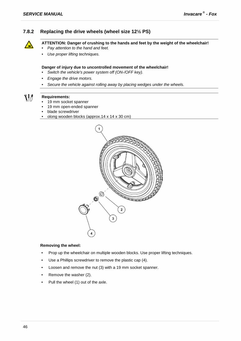
7.8.2 Replacing the drive wheels (wheel size 12½ PS)
ATTENTION: Danger of crushing to the hands and feet by the weight of the wheelchair! · Pay attention to the hand and feet. · Use proper lifting techniques.
Danger of injury due to uncontrolled movement of the wheelchair! · Switch the vehicle's power system off (ON-/OFF key). · Engage the drive motors. · Secure the vehicle against rolling away by placing wedges under the wheels.
Requirements:
· 19 mm socket spanner · 19 mm open-ended spanner · blade screwdriver · olong wooden blocks (approx.14 x 14 x 30 cm)
Removing the wheel:
· Prop up the wheelchair on multiple wooden blocks. Use proper lifting techniques.
· Use a Phillips screwdriver to remove the plastic cap (4).
· Loosen and remove the nut (3) with a 19 mm socket spanner.
· Remove the washer (2).
· Pull the wheel (1) out of the axle.
Invacare ® - Fox SERVICE MANUAL
47
Refitting the wheel:
· Refit the parts in reverse order.
· When installing the wheel, pay attention to the correct direction of rotation.
· Tighten the nut (3) to 35 Nm +/-10% Nm.
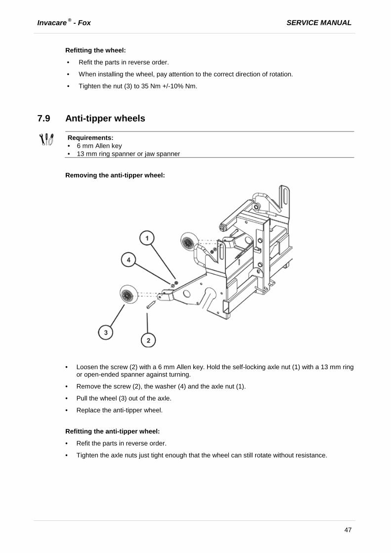
7.9 Anti-tipper wheels
Requirements:
· 6 mm Allen key · 13 mm ring spanner or jaw spanner
Removing the anti-tipper wheel:
· Loosen the screw (2) with a 6 mm Allen key. Hold the self-locking axle nut (1) with a 13 mm ring
or open-ended spanner against turning.
· Remove the screw (2), the washer (4) and the axle nut (1).
· Pull the wheel (3) out of the axle.
· Replace the anti-tipper wheel.
Refitting the anti-tipper wheel:
· Refit the parts in reverse order.
· Tighten the axle nuts just tight enough that the wheel can still rotate without resistance.
SERVICE MANUAL Invacare ® - Fox
48
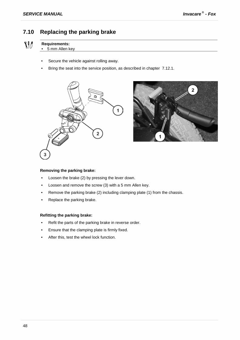
7.10 Replacing the parking brake
Requirements:
· 5 mm Allen key
· Secure the vehicle against rolling away.
· Bring the seat into the service position, as described in chapter 7.12.1.
Removing the parking brake:
· Loosen the brake (2) by pressing the lever down.
· Loosen and remove the screw (3) with a 5 mm Allen key.
· Remove the parking brake (2) including clamping plate (1) from the chassis.
· Replace the parking brake.
Refitting the parking brake:
· Refit the parts of the parking brake in reverse order.
· Ensure that the clamping plate is firmly fixed.
· After this, test the wheel lock function.
Invacare ® - Fox SERVICE MANUAL
49
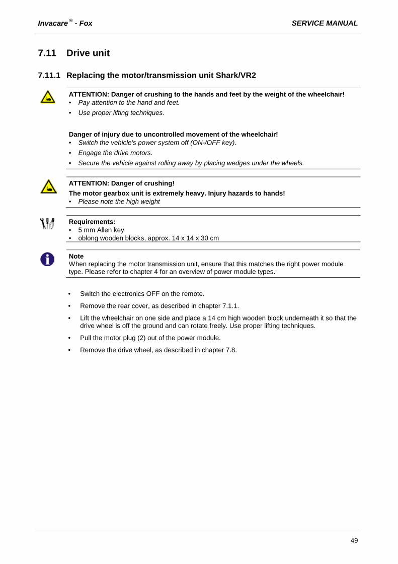
7.11 Drive unit
7.11.1 Replacing the motor/transmission unit Shark/VR2
ATTENTION: Danger of crushing to the hands and feet by the weight of the wheelchair! · Pay attention to the hand and feet. · Use proper lifting techniques.
Danger of injury due to uncontrolled movement of the wheelchair! · Switch the vehicle's power system off (ON-/OFF key). · Engage the drive motors. · Secure the vehicle against rolling away by placing wedges under the wheels.
ATTENTION: Danger of crushing! The motor gearbox unit is extremely heavy. Injury hazards to hands! · Please note the high weight
Requirements:
· 5 mm Allen key · oblong wooden blocks, approx. 14 x 14 x 30 cm
Note
When replacing the motor transmission unit, ensure that this matches the right power module type. Please refer to chapter 4 for an overview of power module types.
· Switch the electronics OFF on the remote.
· Remove the rear cover, as described in chapter 7.1.1.
· Lift the wheelchair on one side and place a 14 cm high wooden block underneath it so that the drive wheel is off the ground and can rotate freely. Use proper lifting techniques.
· Pull the motor plug (2) out of the power module.
· Remove the drive wheel, as described in chapter 7.8.

SERVICE MANUAL Invacare ® - Fox
50
Removing the motor/transmission unit:
· Loosen the four Allen screws (4) with a 5 mm Allen key.
· Remove the screws (4) together with the washers.
· Pull the motor transmission unit (3) downwards out of the chassis. Take into account the heavy weight of the unit.
· Replace the drive unit.
Refitting the motor/transmission unit:
Note
Before refitting a new motor-transmission unit, check to see whether this should be fitted to the left-hand or right-hand side of the mobility device. The drive units are different. Note the labelling on the motor plug.
· Refit the motor transmission unit in the reverse order.
· Reconnect the motor cable (2) to the power module.
· Make sure that the motor cable cannot be pinched or bent, and that it is not exposed to chafing in any place.
· Tighten the screws (4) to 7 Nm +/-1 Nm.
· To conclude, you should always carry out a trial run to test the vehicle functions.
Invacare ® - Fox SERVICE MANUAL
51
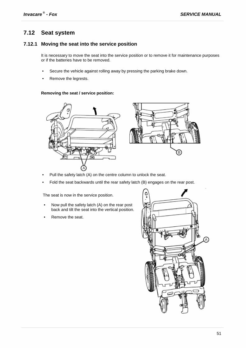
7.12 Seat system
7.12.1 Moving the seat into the service position
It is necessary to move the seat into the service position or to remove it for maintenance purposes or if the batteries have to be removed. · Secure the vehicle against rolling away by pressing the parking brake down.
· Remove the legrests.
Removing the seat / service position:
· Pull the safety latch (A) on the centre column to unlock the seat.
· Fold the seat backwards until the rear safety latch (B) engages on the rear post.
The seat is now in the service position. · Now pull the safety latch (A) on the rear post
back and tilt the seat into the vertical position.
· Remove the seat.

SERVICE MANUAL Invacare ® - Fox
52
Installing the seat:
· Place the seat vertically onto its holder again.
· Fold the seat forward.
· Make sure the safety latches (A) on the center post engage.
Invacare ® - Fox SERVICE MANUAL
53
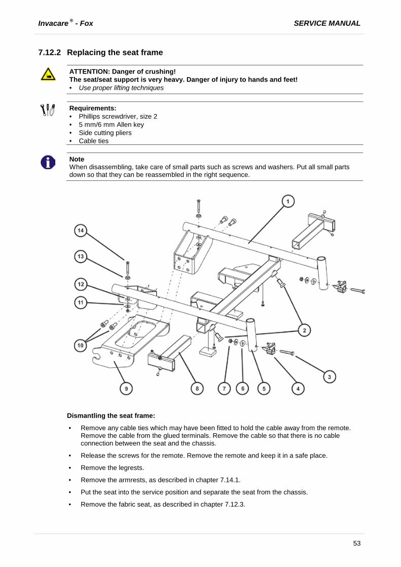
7.12.2 Replacing the seat frame
ATTENTION: Danger of crushing! The seat/seat support is very heavy. Danger of injury to hands and feet! · Use proper lifting techniques
Requirements:
· Phillips screwdriver, size 2 · 5 mm/6 mm Allen key · Side cutting pliers · Cable ties
Note
When disassembling, take care of small parts such as screws and washers. Put all small parts down so that they can be reassembled in the right sequence.
Dismantling the seat frame:
· Remove any cable ties which may have been fitted to hold the cable away from the remote. Remove the cable from the glued terminals. Remove the cable so that there is no cable connection between the seat and the chassis.
· Release the screws for the remote. Remove the remote and keep it in a safe place.
· Remove the legrests.
· Remove the armrests, as described in chapter 7.14.1.
· Put the seat into the service position and separate the seat from the chassis.
· Remove the fabric seat, as described in chapter 7.12.3.

SERVICE MANUAL Invacare ® - Fox
54
· Loosen and remove the bolts (3) incl. fixing (4), the round disk (6), the washer and the nut (7) from the legrest holder. Repeat these stages on the other side of the seat frame (1).
· Remove the backrest unit, as described in chapter 7.13.
· Remove the fixing bolts (2) for the armrests (8).
· Loosen and remove the bolt (14) incl. rosette (13), the round disk (12), the washer (11) and the nut from the seat extension.
· Loosen and remove the bolts (10) with a 6 mm Allen key. Repeat these stages on the other side of the seat frame (1).
· Remove the seat frame from the seat support (9).
· Replace the seat frame or seat support.
Refitting the seat frame:
· Assemble the parts in reverse order.
Note
When refitting, ensure that the round disks (6) (12) are in the correct position.
· Check all functions of the vehicle and go for a test drive.

Invacare ® - Fox SERVICE MANUAL
55
7.12.3 Replacing the fabric seat (padded)
ATTENTION: Danger of crushing! The seat/seat support is very heavy. Danger of injury to hands and feet! · Use proper lifting techniques
Requirements:
· Phillips screwdriver, size 2 · 8 mm open-ended spanner
· Remove the seat cushion.
· Remove the armrests as described in chapter 7.14.1.
Dismantling the fabric seat:
· Loosen and remove the six screws (1) including rosette with a Phillips screwdriver.
· Loosen and remove the screw (4) including the rosette, the circular washer (3), washer and the nut (2). The screw (4) is also used to adjust the seat depth (5), see chapter 9.1.2.1.
· Replace the fabric seat.
Refitting the fabric seat:
· Refit the parts in reverse order.
Note
When refitting, ensure that the round disk (3) is in the correct position. The bolts (4) are fixed by the fabric seat at the end.
· To conclude, you should always carry out a trial run to test the vehicle functions.

SERVICE MANUAL Invacare ® - Fox
56
7.12.4 Replacing the fabric seat (strechted)
ATTENTION: Danger of crushing! The seat/seat support is very heavy. Danger of injury to hands and feet! · Use proper lifting techniques
Requirements:
· Phillips screwdriver, size 2 · 8 mm open-ended spanner
Dismantling the fabric seat:
· Loosen and remove the eight screws (1) including rosette with a Phillips screwdriver.
· Replace the fabric seat.
Invacare ® - Fox SERVICE MANUAL
57
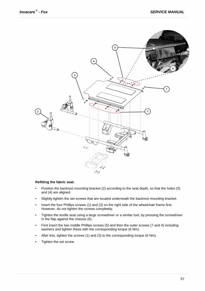
Refitting the fabric seat:
· Position the backrest mounting bracket (2) according to the seat depth, so that the holes (3) and (4) are aligned.
· Slightly tighten the set screws that are located underneath the backrest mounting bracket.
· Insert the four Phillips screws (1) and (3) on the right side of the wheelchair frame first. However, do not tighten the screws completely.
· Tighten the textile seat using a large screwdriver or a similar tool, by pressing the screwdriver in the flap against the chassis (6).
· First insert the two middle Phillips screws (5) and then the outer screws (7 and 4) including washers and tighten these with the corresponding torque (6 Nm).
· After this, tighten the screws (1) and (3) to the corresponding torque (6 Nm).
· Tighten the set screw.
SERVICE MANUAL Invacare ® - Fox
58
Note
The screws (3) and (4) are also used to adjust the seat depth with the backrest unit (2), see chapter 9.1.2.2.
· Push the flap under the seat frame.
· Refit the armrests as described in chapter 7.14.1.
· To conclude, you should always carry out a trial run to test the vehicle functions.

Invacare ® - Fox SERVICE MANUAL
59
7.12.5 Replacing the seat plate
ATTENTION: Danger of crushing! The seat/seat support is very heavy. Danger of injury to hands and feet! · Use proper lifting techniques
Requirements:
· Phillips screwdriver, size 2 · 8 mm open-ended spanner
· Remove the seat cushion.
· Remove the armrests as described in chapter 7.14.1.
Dismantling the seat plate:
· Loosen and remove the six Phillips screws (1) with a Phillips screwdriver.
· Lift the seat plate from the seat frame.
· Replace the seat plate or fit the fabric seat if required as described in chapter 7.12.4
Refitting the seat plate:
· Refit the parts in reverse order.

SERVICE MANUAL Invacare ® - Fox
60
7.12.6 Replacing the safety latch
Requirements:
· 24 mm open-ended spanner
· Remove the seat, as described in chapter 7.12.1.
Dismantling the safety latch:
· Loosen the adjusting ring using a 24 mm open-ended spanner.
· Unscrew the safety latch (1) and replace it.
Refitting the safety latch:
· Refit the parts in reverse order.
· Screw the safety latch (1) in and adjust it.
7.12.7 Adjusting the safety latch
Requirements:
· 24 mm open-ended spanner
· Loosen the adjusting ring using a 24 mm open-ended spanner.
· Screw the safety latch (1) in so that the spring-loaded catch engages securely and is flush with the outside edge when it is pulled.
· Tighten the adjusting ring hand-tight with a 24 mm open-ended spanner (15 Nm +/-1 Nm).
Invacare ® - Fox SERVICE MANUAL
61
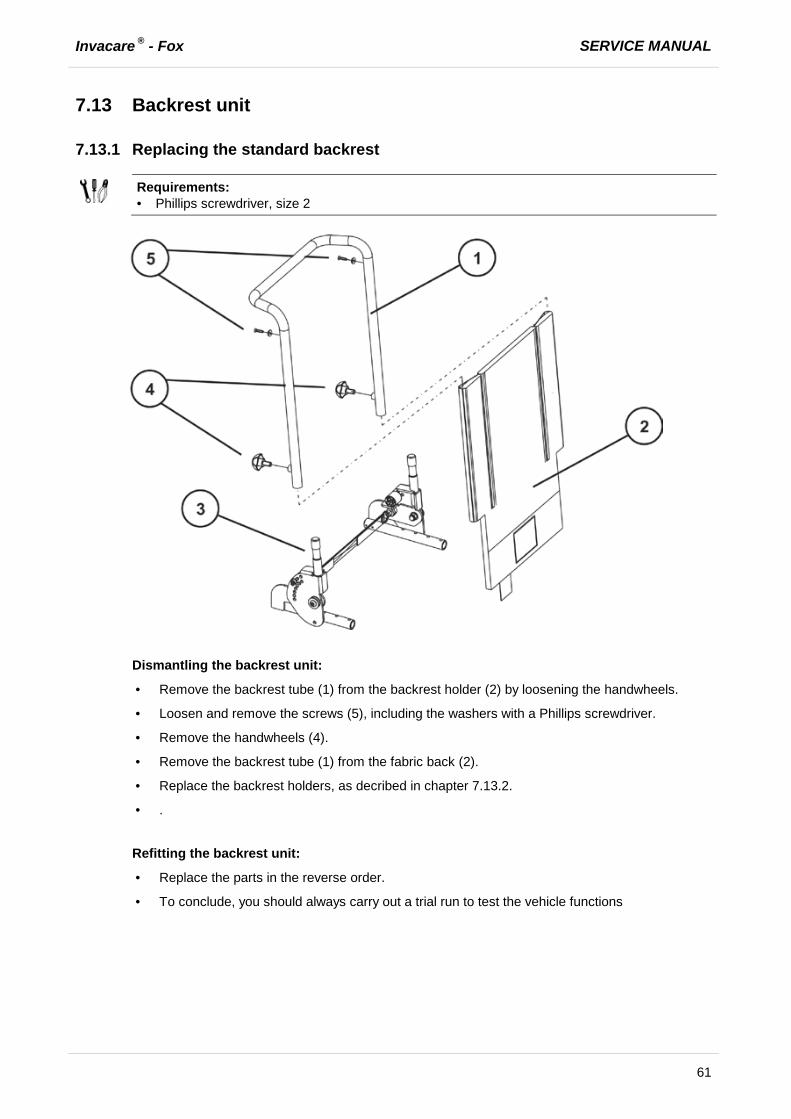
7.13 Backrest unit
7.13.1 Replacing the standard backrest
Requirements:
· Phillips screwdriver, size 2
Dismantling the backrest unit:
· Remove the backrest tube (1) from the backrest holder (2) by loosening the handwheels.
· Loosen and remove the screws (5), including the washers with a Phillips screwdriver.
· Remove the handwheels (4).
· Remove the backrest tube (1) from the fabric back (2).
· Replace the backrest holders, as decribed in chapter 7.13.2.
· .
Refitting the backrest unit:
· Replace the parts in the reverse order.
· To conclude, you should always carry out a trial run to test the vehicle functions

SERVICE MANUAL Invacare ® - Fox
62
7.13.2 Replacing a standard backrest with quick release
Requirements:
· Phillips screwdriver, size 2 · 5 mm Allen key · 13 mm open-ended spanner
Note
When disassembling, take care of small parts such as screws and washers. Put all small parts down so that they can be reassembled in the right sequence.
Dismantling the backrest unit:
· Remove the backrest unit, as described in chapter 7.13.1.
· Loosen and remove the Allen screw (9) including washers (8), bushings (5) and nut (3) on the left-hand and right-hand side of the chair. Use an Allen key and an open-ended spanner.
· Pull the quick release cord (1) to unlock the backrest tube.

Invacare ® - Fox SERVICE MANUAL
63
· Loosen and remove the Allen screws (9) including washers (8), stopper (12) and nut (13) on the left-hand and right-hand side of the chair. Use an Allen key and an open-ended spanner.
· Remove the backrest holders (6) including quick release cord (1).
Refitting the backrest unit:
· Replace the parts in the reverse order.
· Refit the backrest unit, as described in chapter 7.13.1.
· To conclude, you should always carry out a trial run to test the vehicle functions.

SERVICE MANUAL Invacare ® - Fox
64
7.14 Armrest
7.14.1 Replacing the armrest
Requirements:
· 6 mm Allen key
Dismantling the armrest:
· Loosen the Allen screws (3 and 4) with a 6 mm Allen key and pull the armrest out of the holder.
· Replace the armrest.
Refitting the armrest:
· Refit the parts in reverse order.
Invacare ® - Fox SERVICE MANUAL
65
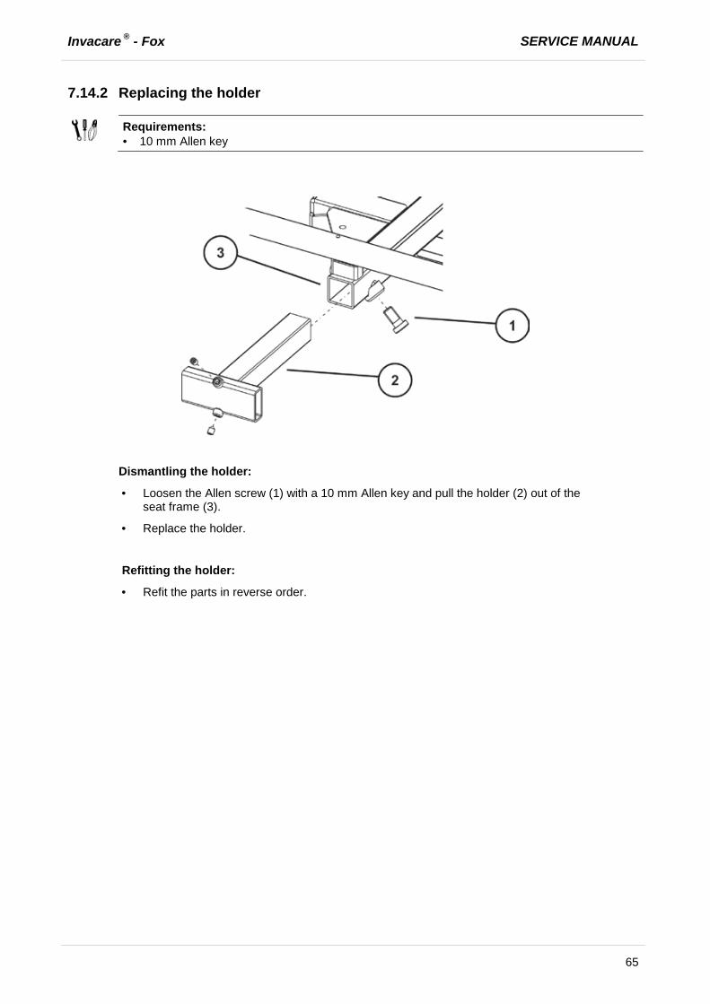
7.14.2 Replacing the holder
Requirements:
· 10 mm Allen key
Dismantling the holder:
· Loosen the Allen screw (1) with a 10 mm Allen key and pull the holder (2) out of the seat frame (3).
· Replace the holder.
Refitting the holder:
· Refit the parts in reverse order.
SERVICE MANUAL Invacare ® - Fox
66
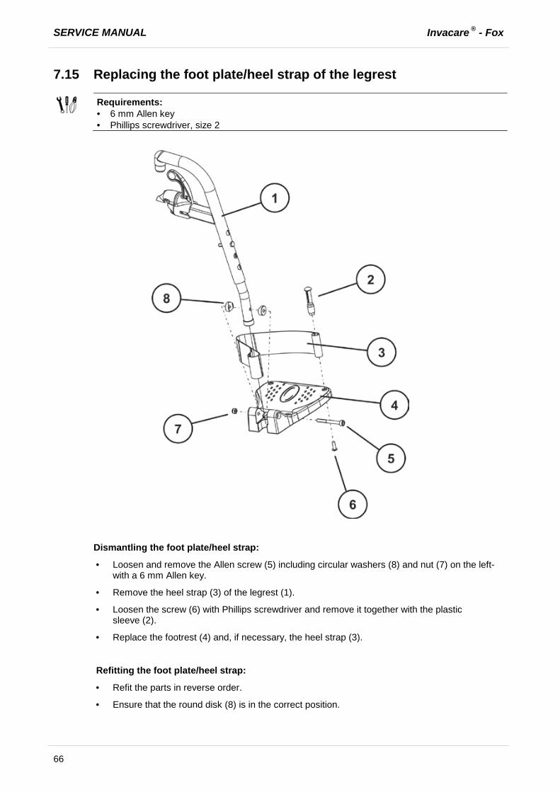
7.15 Replacing the foot plate/heel strap of the legrest
Requirements:
· 6 mm Allen key · Phillips screwdriver, size 2
Dismantling the foot plate/heel strap:
· Loosen and remove the Allen screw (5) including circular washers (8) and nut (7) on the left-with a 6 mm Allen key.
· Remove the heel strap (3) of the legrest (1).
· Loosen the screw (6) with Phillips screwdriver and remove it together with the plastic sleeve (2).
· Replace the footrest (4) and, if necessary, the heel strap (3).
Refitting the foot plate/heel strap:
· Refit the parts in reverse order.
· Ensure that the round disk (8) is in the correct position.
Invacare ® - Fox SERVICE MANUAL
67
8 Installing accessories
8.1 Replacing the holding strap
Requirements:
· 13 mm open-ended spanner · 5 mm Allen key
Note
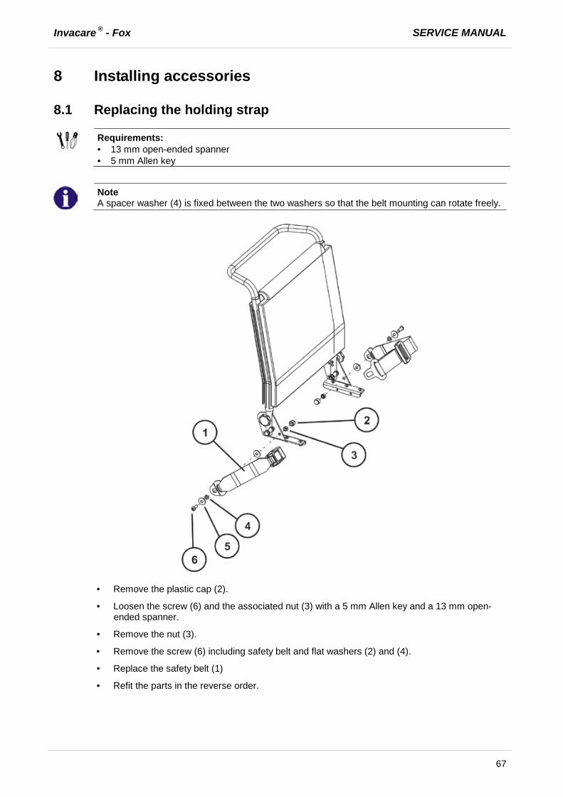
A spacer washer (4) is fixed between the two washers so that the belt mounting can rotate freely.
· Remove the plastic cap (2).
· Loosen the screw (6) and the associated nut (3) with a 5 mm Allen key and a 13 mm open-ended spanner.
· Remove the nut (3).
· Remove the screw (6) including safety belt and flat washers (2) and (4).
· Replace the safety belt (1)
· Refit the parts in the reverse order.
SERVICE MANUAL Invacare ® - Fox
68
8.2 Curb climber
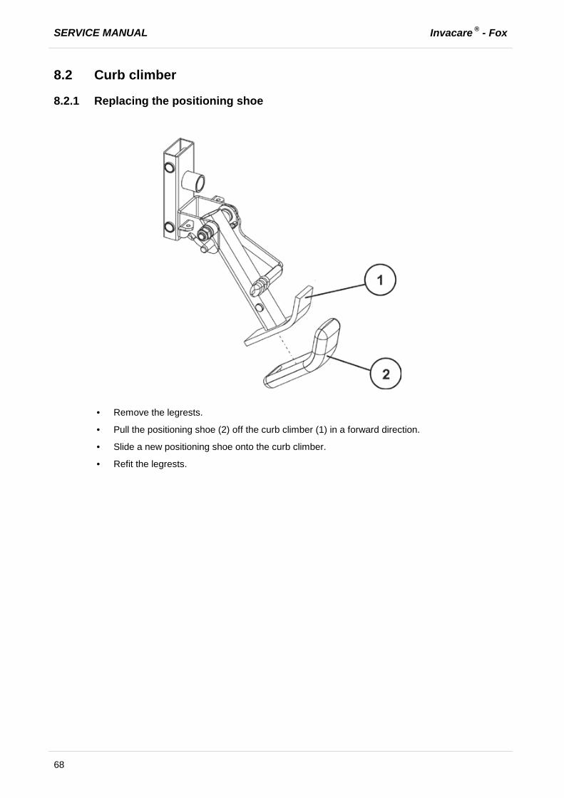
8.2.1 Replacing the positioning shoe
· Remove the legrests.
· Pull the positioning shoe (2) off the curb climber (1) in a forward direction.
· Slide a new positioning shoe onto the curb climber.
· Refit the legrests.

Invacare ® - Fox SERVICE MANUAL
69
8.2.2 Replacing the curb climber
ATTENTION: Danger of crushing! Injury hazards to hands! The gas pressure spring is under pressure! · Take care with your hands. Use suitable tools.
Requirements:
· 5 mm Allen key · 13 mm open-ended spanner · pipe wrench
· Remove the legrests.
· Dismantle the swinging axle as described in chapter 7.7.2.
· Place a wooden block approx. 14 cm high under the curb climber.
Dismantling the curb climber:
· Loosen the Allen screw (4) and use a pipe wrench to pull the gas pressure spring (3) out of its holder.
· Loosen and remove the Allen screw (1) incl. switch lever (2), bearing sleeve (10), gas pressure spring (3), washer (7) and nut (6).
The gas pressure spring (3) is fixed to the bottom part of the switch lever (2) with a washer (9) and nut (8).

SERVICE MANUAL Invacare ® - Fox
70
Note
When disassembling, take care of small parts such as screws and washers. Put all small parts down so that they can be reassembled in the right sequence.
Refitting the curb climber:
· Assemble the parts in the reverse order.
· If necessary, refit the support shoe to the curb climber as described in chapter 8.2.1.
· Refit the legrests.
Note
When applying the correct tightening torque to the nut (6), ensure that the curb climber is seated so that it can move.
8.3 Further accessories
Note
The installation instructions for additional accessories are available at your Invacare® specialist supplier or directly from Invacare®.
Invacare ® - Fox SERVICE MANUAL
71
9 Adjusting the seating position In order to adapt the mobility device optimally to the requirements of the user, we recommend that you ask your authorised Invacare® the dealer toadjust the seat depth individually.
Adapting the seat to the user's seating position depends on which seat has been fitted, and should be carried out in the following sequence.
1. Adjusting the lower leg length and seat depth, see chapter 9.1. 2. Adjusting the seat height and seat tilt, see chapter 9.2 and chapter 9.3. 3. Adjusting the center of gravity of the seat frame, see chapter 9.4. 4. Checking that the swivel castors can move freely. 5. Repetition of steps 3 to 4, if necessary.
WARNING!
Danger of injury hazard after tilting of mobility caused by blocked steering wheels. · Always check the seat depth settings for both forward and reverse movement.Make sure that
steering wheels can rotate freely and have not contact to any fixed mobility device component.
CAUTION!
Any changes to the drive program can affect the driving characteristics and the tipping stability of the vehicle! · Changes to the drive program may only be carried out by trained Invacare® specialist
dealers! · Invacare® supplies all mobility aids with a standard drive program ex-works. Invacare® can
only give a warranty for safe vehicle driving behaviour - especially tipping stability - for this standard drive program!
WARNING: Danger of crushing!
The seat is very heavy. Danger of injury to hands and feet. · Pay attention to the hand and feet · Use proper lifting techniques
SERVICE MANUAL Invacare ® - Fox
72
9.1 Adjusting the lower leg length and seat depth
9.1.1 Adjusting the lower leg length
Invacare® offers a range of legrests which can be adjusted individually. See operation manual.
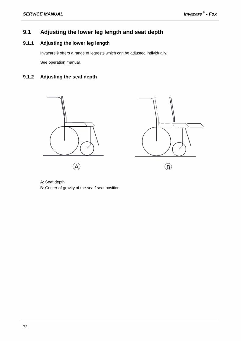
9.1.2 Adjusting the seat depth
A: Seat depth B: Center of gravity of the seat/ seat position
Invacare ® - Fox SERVICE MANUAL
73
9.1.2.1 Adjusting the seat depth via the backrest unit (fabric seat padded)
ATTENTION: Danger of crushing! The seat/seat support is very heavy. Danger of injury to hands and feet! · Use proper lifting techniques
Requirements:
· Phillips screwdriver, size 2 · 8 mm open-ended spanner · Side cutting pliers · Cable ties
Note
When disassembling, take care of small parts such as screws and washers. Put all small parts down so that they can be reassembled in the right sequence.
· Remove the seat, as described in chapter 7.12.3.
· Push the backrest unit (3) as far as the required drill hole in the seat frames (1).
· Fix the seat as described in chapter 7.12.3.
· Fix the bolts (2) incl. rosette, round disc, washer and nut. Ensure that the round disc is fitted correctly.
Note
The screws (2) are fixed by the fabric seat (see chapter 7.12.3). · Check all functions during a test drive.

SERVICE MANUAL Invacare ® - Fox
74
9.1.2.2 Adjusting the seat depth via the backrest unit (fabric seat strechted)
ATTENTION: Danger of crushing! The seat/seat support is very heavy. Danger of injury to hands and feet! · Use proper lifting techniques
Requirements:
· Phillips screwdriver, size 2 · 8 mm open-ended spanner · Side cutting pliers · Cable ties
Note
When disassembling, take care of small parts such as screws and washers. Put all small parts down so that they can be reassembled in the right sequence.
· Loosen and remove rhe screws (2).
· Position the backrest mounting bracket (3) according to the seat depth, so that the drill hole aligns with the seat frame at (2) and (3).
· Tighten the set screw underneath the backrest mounting bracket (3) slightly.
· Insert the backrest tube into the backrest mounting bracket as described in chapter 7.13.
· Fix the seat as described in chapter 7.12.4 or 7.12.5.
Note
The screws (2) are fixed by the fabric seat (see chapter 7.12.4). · Check all functions during a test drive.

Invacare ® - Fox SERVICE MANUAL
75
9.2 Adjusting the seat height
9.2.1 Adjusting seat height above centre column
See user manual.
9.2.2 Adjusting seat height above seat support
ATTENTION: Danger of crushing! The seat/seat support is very heavy. Danger of injury to hands and feet! · Use proper lifting techniques
Requirements:
· 6 mm Allen key · 8 mm open-ended spanner
Note
When disassembling, take care of small parts such as screws and washers. Put all small parts down so that they can be reassembled in the right sequence.
· Put the seat into the service position as described in chapter 7.12.1 and separate the seat from the chassis.
· Loosen and remove the bolts (3) with a 6 mm Allen key. Hold the nut (in the figure (2) this is covered) against turning using an 8 mm open-ended spanner. Repeat these stages on the other side of the seat frame (1).

SERVICE MANUAL Invacare ® - Fox
76
· Fix the bolts (3) in the required drill hole (A or B).
Fixing (A) = short wheelbase - 51 cm seat height - high/rear
Fixing (B) = long wheelbase - 51 cm seat height - high/front
· Place the seat vertically onto its holder again.
· Fold the seat forwards.
· Ensure that the safety latches engage on the centre column.
· Check all functions of the vehicle and go for a test drive.
9.3 Adjusting the seat tilt
See user manual.
9.4 Adjusting the center of gravity of the seat The center of gravity of the seat can be adjusted by mounting the seat frame farther towards the front or the rear on the seat.
CAUTION!
The seating system of the electric wheelchair is delivered ex works with an optimally adjusted center of gravity. Any change in this adjustment setting can negatively influence the stability of the electric wheelchair. · You must perform an individual risk analysis every time you change the center of gravity of
the seating position, in order to ensure the safety and stability of the electric wheelchair.

Invacare ® - Fox SERVICE MANUAL
77
A: Seat depth B: Center of gravity of the seat/ seat position
Note
The user weight and seat depth have strong influences on the choice of the Center of gravity of the seat. If the user is heavy and the seat depth is greater, the focus should be the farther back.
For best possible driving characteristics of rear-wheel drive wheelchairs, the weight to be distributed: 30 – 40 % front and 60 - 70 % rear.
WARNING!
Danger of damage due to collisions of the legrests with other parts of the wheelchair! · Set the legrests to the smallest angle before adjusting the seat center of gravity. · Pay attention with adjusting the seat center of gravity that the legrests do not touch any other
parts of the wheelchair. This ensures that the legrests can not collide with other parts of the wheelchair.

SERVICE MANUAL Invacare ® - Fox
78
ATTENTION: Danger of crushing! The seat/seat support is very heavy. Danger of injury to hands and feet! · Use proper lifting techniques
Requirements:
· 6 mm Allen key · 8 mm open-ended spanner
Note
When disassembling, take care of small parts such as screws and washers. Put all small parts down so that they can be reassembled in the right sequence.
· Put the seat into the service position as described in chapter 7.12.1 and separate the seat from
the chassis.
· Loosen and remove the bolts (3) with a 6 mm Allen key. Hold the nut (in the figure (2) this is covered) against turning using an 8 mm open-ended spanner. Repeat these stages on the other side of the seat frame (1).
Invacare ® - Fox SERVICE MANUAL
79
· Fix the bolts (3) in the required drill hole (A or B).
Fixing (A) = short wheelbase - 48 cm seat height - deep/rear
Fixing (B) = long wheelbase - 48 cm seat height - deep/front
· Place the seat vertically onto its holder again.
· Fold the seat forwards.
· Ensure that the safety latches engage on the centre column.
· Check all functions of the vehicle and go for a test drive.