intuitive programming system walk-through for …int.haascnc.com/doclib/manual/es0609.pdfthese...
TRANSCRIPT

ES0609 rev D 4/09 1
IntuitiveProgrammingSystemWalk-ThroughFor Lathes

ES0609 rev D 4/09 2
IntroductIon
These instructions are an in-depth look at each of the Intuitive Programming System (IPS) menus. A more formal description is given for each of the entries to help better define the on-screen help for new users.
These instructions are to be used with the Lathe Operator’s Manual (96-8700) and Toolroom Lathe Operator’s Addendum (96-0112)
The menus are navigated by using the left and right arrow keys. To select a menu item, press Write/Enter. Some menus have sub-menus, in which case, use the left and right arrow keys and press Write/Enter to select a sub-menu.
Use the arrow keys to navigate through the variables, enter values by using the number pad, and then press Write/Enter.
To exit, or go back to another selection, press Cancel.
Pressing any of the buttons under the “Display” heading will exit the IPS menus, as will any of the mode keys (i.e. Edit, Mem, MDI, etc.). To return to the IPS menu, press Handle Jog.
A representation of the machine keypad is included at the end of this document for reference.
This guide will help the user develop full CNC programs by means of the IPS screen. Note that a program entered through the Toolroom Lathe screens is also accessible by going to full CNC MDI mode. The program can be edited and saved from the full CNC mode.
NOTE: The IPS menu is displayed at power up, and is available in the following configurations:
• 10” LCD and software version 7.xx and earlier - IPS • 15” LCD and software version 8.03 and earlier - IPS (upgradable to Profile Creator)
• 15” LCD and software version 8.04A and later - IPS with Profile Creator
Manual Mode
Power on the machine and press RESET until all alarms have cleared. Press POWER ON/RESTART to zero the machine. The IPS menu can now be accessed by pressing MDI DNC, then pressing PRGRM CONVRS. Press WRITE/ENTER to display the IPS menu MANUAL tab.
GROOVINGTHREAD RE-CUTTHREADINGDRILL & TAPCHAMFER & RADIUSTURN & FACECHAMFERSETUPMANUAL
X AND Z AXESTHE AXES CAN BE ELECTRONICALLY LOCKED AND UNLOCKED. THIS IS SHOWN BYXZ-MAN DISPLAYED AT THE BOTTOM OF THE SCREEN. IN THIS MODE BOTH THEX AND Z AXES ARE UNLOCKED AND CAN BE POSITIONED USING THE MANUALHAND WHEELS. PRESSING [SHIFT] AND EITHER [+X] OR [-X], [+Z], OR[-Z] WILL ELECTRONICALLY LOCK THAT AXIS. PRESSING [SHIFT] AND THESAME BUTTON A SECOND TIME WILL UNLOCK THE AXIS.
SPINDLETHE SPINDLE IS COMMANDED BY ENTERING A VALUE FOR THE SPINDLE SPEEDAND PRESSING EITHER THE [FWD] OR [REV] BUTTONS. THE SPINDLE SPEEDOVERRIDE KEYS (+/-10%) CAN BE USED TO ADJUST THE COMMANDED SPEED.

ES0609 rev D 4/09 3
X and Z AxesJust below the on-screen text is a line of text that shows the state the lathe is in. For example, “X -MAN” means the X -axis is in manual mode. No text beneath the on-screen help means both axes (X and Z are locked. In this case the axes can be jogged, by pressing +X/-X or +Z/-Z and then using the jog handle on the pendant. Select a jog speed before using the jog handle.
SpindleThe spindle is controlled using the keys on the control pendant. Enter a spindle speed; for example, press 5, then 0, then Write/Enter. This will enter a speed of 50RPM. Ensure the area around the spindle is free of tools and workpieces, press the hold to run switch and then press either the FWD or REV button.
The spindle speed override keys ( +/- 10%) can be used to adjust the commanded speed. This also works on most screens.
The spindle is stopped by letting go of the hold to run switch, pressing Reset, or the pressing the Stop button.
Setup
Stock SetupGROOVINGGROOVINGTHREAD RE-CUTTHREADINGDRILL & TAPCHAMFER & RADIUSTURN & FACEMANUALSETUP
STOCK TOOL WORK TAILSTOCK
STOCK DIA.
STOCK LENGTH
STOCK FACE0.1000 in
HOLE SIZE0.0000 in
JAW THICKNESS2.0000 in
2.0000 in
1.5000 in
CLAMP STOCK
JAW HEIGHT
STEP HEIGHT
3.0000 in
3.0000 in
0.5000 in
STOCK JAWS BAR FEEDER
Stock Dia. – Controls the diameter of the raw part that will be displayed in live image.Stock Length – Controls the length of the raw part that will be displayed in live image.Stock Face – Controls the Z stock face of the raw part that will be displayed in live image.Hole Size – Controls the stock hole of the raw part that will be displayed in live image. Jaw Thickness – Controls the thickness of the chuck jaws that will be displayed in live image.Jaw Height – Controls the height of the chuck jaws that will be displayed in live image.Step Height – Clamp Stock – Controls the clamp stock size of the chuck jaws that will be displayed in live image.Push Length –

ES0609 rev D 4/09 4
Tool OffsetsTool offsets are described in detail in the Operator’s manual. See the “Tool Nose Compensation” section within the “Operation/Programming” Tab for specific instructions on Radius, Radius Wear, Taper, and Tip.
STOCK TOOL WORK TAILSTOCK
TOOL1
TOOL TYPE
OFFSET NUM
X OFFSET0.0000 in
Z WEAR
RADIUS
TIP0
TOOL SHANK0.0000 in
TL THICKNESS
INSRT THCKNES
TOOL NOSE
INSERT HEIGHT
X WEAR TOOL LENGTH FROM CENTER
0.0000 inCUT OFF
1
Z OFFSET0.0000 in
STEP HEIGHT DIAMETER
0.0000 in
0.0000 in
0.0000 in
0.0000 in
0 deg
0.0000 in
0.0000 in
0.0000 in
0.0000 in
0.0000 in
Selected Tool: 1Active Tool: 1
Press [TURRET FWD] or[TURRET REV] to change theselected tool.Press [NEXT TOOL] to makeselected tool active.
GROOVINGGROOVINGTHREAD RE-CUTTHREADINGDRILL & TAPCHAMFER & RADIUSTURN & FACEMANUALSETUP
Tool – The current tool number. Use the turret FWD/REV or the Next Tool buttons to set-up another tool.Tool Type – Right/Left arrows select among 16 tool types: Drill, Tap, Vert Tap, Vert Drill, End Mill, V End Mill, Ballnose, V Ballnose, OD Turn, ID Bore, OD Groove, ID Groove, Face Groove, OD Thread, ID Thread and Cut Off.Offset Num –X Offset – The X axis offset for the current tool. Press X Dia Meas to record this position.X Wear – The amount of tool wear, in the X axis for the current tool.Z Offset – The Z axis offset for the current tool. Press Z Face Meas to record this position.Z Wear – The amount of tool wear, in the Z axis for the current tool.Radius** – The tip radius of the current tool.Tip** – Tool tip direction will be a value of 0-9. Must be entered to use Cutter CompensationTool Shank – Tool Length – Step Height – TL Thickness – Tool Nose – The nose radius of the current tool.Insert Height – From Center – Diameter – Compensation value for part deflection.**Must be entered to use Cutter Compensation; See the Operator’s manual for information on Cutter Compensation.

ES0609 rev D 4/09 5
Work Offsets
STOCK TOOL WORK TAILSTOCK
X OffsetWrk Zero Ofst
540.
Z Offset
0.
GROOVINGGROOVINGTHREAD RE-CUTTHREADINGDRILL & TAPCHAMFER & RADIUSTURN & FACEMANUALSETUP
Work Zero Offset – Press the Up and Down arrows to change the displayed Work Zero Offset.X Offset – Press Write to add or F1 to set position. Enter a value and either press Write to add the value to the current value, or F1 to replace the value with the entered value.Z Offset – Press Write to add F1 to set or Part Zero Set to record current position. Enter a value and either press Write to add the value to the current value, or F1 to replace the value with the entered value. Press Part Zero Set to record the Z Offset current position.
Tailstock Setup
STOCK TOOL WORK TAILSTOCK
LIVE CTR ANG60.000 deg
DIAMETER
LENGTH2.0000 in
TS POSITION
TS OFFSET
RETRACT DIST0.0000 in
X CLEARANCE
Z CLEARANCE
ADVANCE DIST0.0000 in
0.0000 in
1.2500 in
NOT MODIFIABLETS HOLD POINT is the sum ofTS POSITION and TS OFFSET andis stored in setting 107.
-10.0000 in
0.0000 in -0.5000 in
TS HOLD POINT0.0000 in
GROOVINGGROOVINGTHREAD RE-CUTTHREADINGDRILL & TAPCHAMFER & RADIUSTURN & FACEMANUALSETUP
Live Center Angle – Controls center angle of tailstock.Diameter – Controls the diameter of the tailstock.Length – Controls the length of the tailstock.
TS Position – TS Offset –
ES0609 rev D 4/09 6
Retract Dist – The distance from the Hold Point (Setting 107) the tail stock will retract when commanded. This setting should be a positive value. Press Write to add F1 to set or Part Zero Set to record current position. Enter a value and either press Write to add the value to the current value, or F1 to replace the value with the entered value. Press Part Zero Set to record the Z Offset current position.
Advance Dist – When the tail stock is moving toward the Hold Point (Setting 107), this is the point where it will stop its rapid movement and begin a feed. This setting should be a positive value. Press the Up and Down arrows to change the displayed Work Zero Offset.X Clearance – Works with Z Clearance to define a tail stock travel restriction zone that limits interaction between the tail stock and the tool turret. It determines the X-axis travel limit when the difference between the Z-axis location and the tail stock location falls below the value in Z Clearance. If this condition occurs and a program is running, an alarm is generated. When jogging, no alarm is generated, but travel is limited. Press Write to add or F1 to set position. Enter a value and either press Write to add the value to the current value, or F1 to replace the value with the entered value. When highlighting X CLEARANCE, pressing X DIA MEAS takes the value of the X axis and places it in X CLEARANCE. Pressing ORIGIN when highlighting X CLEARANCE sets clearance to max travel.Z Clearance – Minimum allowable difference between the Z-axis and the tail stock. A value of -1.0000 means that when the X-axis is below the X clearance plane, the Z-axis must be more than 1 inch away from the tail stock position in the Z-axis negative direction. The default value for this setting is zero. Press Write to add F1 to set or Part Zero Set to record current position. Enter a value and either press Write to add the value to the current value, or F1 to replace the value with the entered value. Press Part Zero Set to record the Z Offset current position. When highlighting Z CLEARANCE, pressing Z FACE MEAS takes the value of the Z axis and places it in Z CLEARANCE. Pressing ORIGIN when highlighting Z CLEARANCE sets clearance to zero.
autoMatIc Mode
On each of the following interactive screens, the user is asked to enter data needed to complete common machining tasks. When all data has been entered, press “Cycle Start” to begin the machining process.
The following are examples of the types of the Automatic Mode screens and the definitions of the variables that will need to be entered.
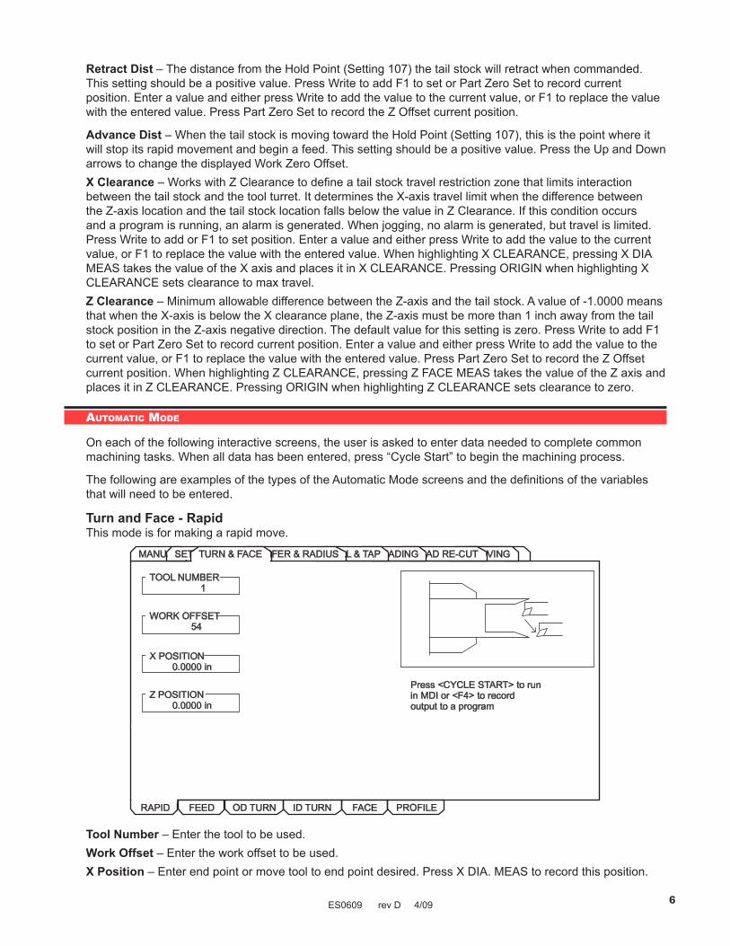
Turn and Face - RapidThis mode is for making a rapid move.
GROOVINGTHREAD RE-CUTTHREADINGDRILL & TAPCHAMFER & RADIUSMANUALSETUP
RAPID FEED OD TURN FACE
TURN & FACE
ID TURN PROFILE
TOOL NUMBER1
WORK OFFSET54
X POSITION0.0000 in
Z POSITION0.0000 in
Press <CYCLE START> to runin MDI or <F4> to recordoutput to a program
Tool Number – Enter the tool to be used.Work Offset – Enter the work offset to be used.X Position – Enter end point or move tool to end point desired. Press X DIA. MEAS to record this position.

ES0609 rev D 4/09 7
Z Position – Enter end point or move tool to end point desired. Press Z FACE MEAS to record this position.
Turn and Face - FeedThis mode provides for straight line (linear) motion from the machines current position to the specified ‘X’ and ‘Z’ end points.
NOTE: The Feed command is a single pass movement for features smaller than the maximum cut depth for the tool. For larger features use the turn and face programs.
RAPID FEED OD TURN FACEID TURN PROFILE
TOOL NUMBER1
WORK OFFSET54
DELTA X0.0000 in
DELTA Z0.0000 in
FEED PER REV0.0000 in
SPINDLE RPM0.0000 in
Press <CYCLE START> to runin MDI or <F4> to recordoutput to a program
GROOVINGTHREAD RE-CUTTHREADINGDRILL & TAPCHAMFER & RADIUSMANUALSETUPTURN & FACE
Tool Number – Enter the tool to be used.Work Offset – Enter the work offset to be used.Delta X – Enter the X-coordinate of the end point of the linear motion desired.Delta Z – Enter the Z-coordinate of the end point of the linear motion desired.*Feed Per Rev. – Enter the feed per revolution (in inches or millimeters).*Spindle RPM – Enter the spindle RPM.*Mandatory ValuesAdvanced Users: In the full CNC mode this is a G01 command.
Turn & Face - OD TurnThis mode is for an outside diameter cut.

ES0609 rev D 4/09 8
RAPID FEED OD TURN FACEID TURN PROFILE
Press <CYCLE START> to runin MDI or <F4> to recordoutput to a program
TOOL NUMBER1
WORK OFFSET54
Z START PT0.0000 in
OUTSIDE DIA.0.0000 in
DIA. TO CUT
Z DIMENSION
DEPTH OF CUT0.0000 in
FEED PER REV0.0000 in
MAX RPM1000
SFM500
FILLET RADII0.0000 in
TOOL NOSE0.0000 in
0.0000 in
0.0000 in
GROOVINGTHREAD RE-CUTTHREADINGDRILL & TAPCHAMFER & RADIUSMANUALSETUPTURN & FACE
Tool Number – Enter the tool to be used.Work Offset – Enter the work offset to be used.Z Start Pt – Enter the Z axis starting point.Outside Dia. – Enter the current diameter of the work piece. Manually measure the diameter.Dia. to Cut – Enter the finished diameter.Z Dimension – Enter the Z axis dimension of the part from the Z start point.Depth of Cut – Enter the depth of cut for each pass of the stock removal.Feed Per Rev – Enter the feed per revolution.MAX RPM – Enter the maximum spindle turning speed.SFM – Enter the Surface Feed per Minute.Fillet Radii – Enter the corner fillet radii or enter ‘0’ for none.Tool Nose – Enter the tool nose radius.
Turn & Face - ID TurnThis mode is for an inside diameter cut.
RAPID FEED OD TURN FACEID TURN PROFILE
Press <CYCLE START> to runin MDI or <F4> to recordoutput to a program
TOOL NUMBER1
WORK OFFSET54
Z START PT0.0000 in
INSIDE DIA.0.0000 in
DIA. TO CUT
Z DIMENSION
DEPTH OF CUT0.0000 in
FEED PER REV0.0000 in
MAX RPM1000
SFM200
FILLET RADII0.0000 in
TOOL NOSE0.0000 in
0.0000 in
0.0000 in
GROOVINGTHREAD RE-CUTTHREADINGDRILL & TAPCHAMFER & RADIUSMANUALSETUPTURN & FACE

ES0609 rev D 4/09 9
Tool Number – Enter the tool to be used.Work Offset – Enter the work offset to be used.Z Start Pt – Enter the Z axis starting point.Inside Dia. – Enter the current diameter of the work piece. Manually measure the diameter.Dia. to Cut – Enter the finished diameter.Z Dimension – Enter the Z axis dimension of the part from the Z start point.Depth of Cut – Enter the depth of cut for each pass of the stock removal.Feed Per Rev – Enter the feed per revolution.MAX RPM – Enter the maximum spindle turning speed.SFM – Enter the Surface Feed per Minute.Fillet Radii – Enter the corner fillet radii or enter ‘0’ for none.Tool Nose – Enter the tool nose radius.Advanced Users: In the full CNC mode this is a G71 command.
Turn & Face - FaceThis mode is for making an end facing cut.
RAPID FEED OD TURN FACEID TURN PROFILE
Press <CYCLE START> to runin MDI or <F4> to recordoutput to a program
TOOL NUMBER1
WORK OFFSET54
OUTSIDE DIA.0.0000 in
DIA. TO CUT0.0000 in
Z DIMENSION
DEPTH OF CUT0.0350 in
FEED PER REV0.0060 in
MAX RPM1000
SFM2000.0000 in
GROOVINGTHREAD RE-CUTTHREADINGDRILL & TAPCHAMFER & RADIUSMANUALSETUPTURN & FACE
Tool Number – Enter the tool to be used.Work Offset – Enter the work offset to be used.Outside Dia. – Enter the current diameter of the work piece. Manually measure the diameter.Dia. to Cut – Enter the finished diameter.Z Dimension – Enter the Z axis dimension of the part from the Z start point.Depth of Cut – Enter the depth of cut for each pass of the stock removal.Feed per Rev – Enter the feed per revolution. This is the distance the tool will move for each revolution of the spindle.MAX RPM – Enter the maximum spindle turning speed.SFM – Enter the Surface Feed per Minute.Advanced Users: In the full CNC mode this is a G72 command.
NOTE: Entering a negative value for “Dia to Cut” causes the tool to pass spindle center and machine the entire face of the part; Do Not enter a value larger than -.100”.

ES0609 rev D 4/09 10
Turn & Face - ProfileThis tab is only available if the machine has a control pendant with a 15” screen and lathe software version 8.04A or later.
RAPID FEED OD TURN FACEID TURN PROFILE
Press <CYCLE START> to runin MDI or <F4> to recordoutput to a program
TOOL NUMBER1
WORK OFFSET54
CUT TYPEHRZ TYPE I
X STOCK ALLOW0.0000 in
NUM OF PASSES
X DISTANCE
Z DISTANCE
FEED PER REV0.0000 in
SPINDLE DIR
CUTTER COMP
COOLANT
MIRROR X
Z STOCK ALLOW0.0000 in
DEPTH OF CUT0.0000 in
MAX RPM0
SFM0
GRAPHIC MODE
PROFILE NUMBR0
FORWARD
OFF
OFF
OFF
OFF
N/A
N/A
N/A
GROOVINGTHREAD RE-CUTTHREADINGDRILL & TAPCHAMFER & RADIUSMANUALSETUPTURN & FACE
Tool Number – Enter the tool to be used.Work Offset – Enter the work offset to be used.Cut Type – Use the left/right cursor keys to select the type of cut (Horizontal, Vertical, Profile, Finish Fwd, Fin-ish Rev).X Stock Allow – Enter the amount to leave on the diameter of the profile.Z Stock Allow – Enter the amount to leave on the faces of the profile.Depth of Cut – Enter the depth of cut for each pass of the stock removal.Num of Passes – Enter the number of cutting passes. (Must be a positive number).X Distance – Enter the X-axis distance and direction from first cut to last. (Radius value).Z Distance – Enter the Z-axis distance and direction from first cut to last.Feed Per Rev – Enter the feed per revolution.MAX RPM – Enter the maximum spindle turning speed.SFM – Enter the Surface Feed per Minute.Spindle Dir – Use the left/right cursor keys to select spindle direction (Forward/Reverse). This depends on tool type.

ES0609 rev D 4/09 11
Cutter Comp – Use the left/right cursor keys to select cutter compensation (Off/Left/Right).Coolant – Use the left/right cursor keys to turn coolant on or off (On/Off).Mirror X – Use the left/right cursor keys to mirror the X axis (On/Off). This allows you to cut on the other side of the part.Graphic Mode – Use the left/right cursor keys to turn on/off Graphic Mode. This allows you to view the pro-cess in graphics.Profile Number – Enter the number of the profile to use, press Enter to open Profile Select or press F1 key.Advanced Users: In the full CNC Mode, this is a G71 command.
Basic Profile Creation (Example)1. Start the machine with IPS active.2. Clear any alarms, then press Power Up/Reset to zero the machine.3. Select the Setup tab, then the Work tab to set up the work offsets.
4. Select the Tool tab (under the Setup tab) to set up the tools to be used.5. Press Cancel a few times to get out of the Setup tab. Select the Turn & Face tab, then the Profile tab.6. Enter the tool number (1), set Cut Type to Horizontal, set X Stock Allow to 0.02, set Z Stock Allow to 0.005, set Depth of Cut to 0.075, set Feed per Rev to 0.01, set Max RPM to 1500, set SFM to 350, set Graphic Mode to ON and Profile Number to 1.7. Select the Profile Number data box and press Write/Enter or press F1 when in the Profile tab. A Profile Selector popup window is displayed. The Profile Selector popup is used to select a profile, alter an existing profile, choose a storage location for a new profile or delete a profile.
*EmptyEmptyEmptyEmptyEmptyEmptyEmptyEmptyEmptyEmptyEmpty
8. Select an ‘Empty’ slot and press Write/Enter to display the Profile Creator screen. This is used to draw a profile on the screen using either the jog handle or entering data directly into the table.
X 1.0000Z - 1.0000Profile Part Number: 1
Jog step size: 0.1
Delta X: 2.0000Delta Z: 0.0000
F1 - HelpF2 - Exit & Save profileF3 - Exit without saveF4 - Activate Zoom
RAPD PTSTART1 FEED1 FEED1 FEED
TYPE
3.50000.00000.50001.00001.0000
0.10000.00001.0000-0.2500-1.0000
0.00000.000090.0000135.0000180.0000
0.00000.00000.00000.00000.5000
0.00000.00000.00000.00000.0000
X POS Z POS ANGLE CHAMFER RADIUS
Profile Creator Screen Hot keys:

ES0609 rev D 4/09 12
F1 – Help screen popup. Lists available keys used in the Profile Creator along with a short description of each key’s function.F2 – Saves the profile on the screen, exits the Profile Creator screen and transfers control back to the Profile tab.F3 – Exits the Profile Creator screen and transfers control back to the Profile tab screen. Does not save the profile’s data.F4 – Activates and de-activates the zoom and scrolling feature.INSERT – Inserts a line into the table. This feature will not work if the table is full (all 30 lines used).ORIGIN – Clears all data in the table.X JOG KEY – Jumps to the X-axis position in the data table for the currently selected row.Z JOG KEY – Jumps to the Z-axis position in the data table for the currently selected row.CURSOR KEYS – Moves around in the data table. If zoom is active, the cursor keys move the part around on the screen.(.0001), (.001), (.01), (.1) – Changes the jog step size while drawing in the graphic window.
To Build the Profile Shown:a. Select the Rapd Pt row. Use the arrow keys to select the X POS column and enter 3.5. Use the arrow keys to select the Z POS column and enter 0.1. Use the arrow keys to go to the beginning of the Start row.
b. Leave the Start PT at X0 Z0. Use the arrow keys to go to the beginning of the next line in the table (4 None). Press 1 to activate a Feed move.
c. Jog X POS to 0.5 by turning the handwheel clockwise, and press Write/Enter.
NOTE: Each handwheel click either increments or decrements the position by 0.1”.
Use the arrow keys to go to the beginning of the next line in the table and press 1 to activate a Feed move.
d. Press Write/Enter until X POS is selected. Jog X to 1.0 and press Write/Enter until Z POS is selected. Jog Z to -0.25 and press Write/Enter.
Go to the beginning of the next line. Press 1 to activate a Feed move.
e. Press Write/Enter until Z POS is selected. Jog Z to -1.0 and press Write/Enter.

ES0609 rev D 4/09 13
Go to the beginning of the next line. Press 1 to activate a Feed move.
f. Press Write/Enter until X POS is selected. Jog X to 2.0 and press Write/Enter.
Go to the beginning of the next line. Press 1 to activate a Feed move.
g. Press Write/Enter until Z POS is selected. Jog Z to -1.5 and press Write/Enter.
Use the cursor keys to go back to the previous line and select the Radius column. Enter 0.25, press Write/Enter and use the cursor keys to come back to this line.
Go to the beginning of the next line. Press 1 to activate a Feed move.
h. Press Write/Enter until X POS is selected. Jog X to 3.0. Press Write/Enter until Z POS is se lected. Jog Z to -2.0 and press Write/Enter.
Go to the beginning of the next line. Press 1 to activate a Feed move.

ES0609 rev D 4/09 14
i. Press Write/Enter until Z POS is selected. Jog Z to -3.0 and press Write/Enter.
j. Press F2 to Save and exit the Profile Creator.
k. Press Cycle Start to cut the profile.
NOTE: The program may be saved to memory from MDI by typing in 0xxxxx and pushing the Alter key. This action moves the program from MDI memory.
If Graphic Mode is set to ON in the Turn & Face Profile screen, when Cycle Start is pressed to run a profile, a graphic screen is displayed showing the graphical representation of the profile.
Graphic Mode
To cut the profile on the other side of the workpiece, set Mirror X to ON in Turn & Face Profile screen (it is not necessary to change Mirror X in Settings). When Cycle Start is pressed, the opposite side of the workpiece is cut, and if Graphic Mode is set to ON, a graphical representation of the mirrored profile is displayed.

ES0609 rev D 4/09 15
Recalling ProfilesThe Profile Selector popup is used to select a profile, alter an existing profile, choose a storage location for a new profile or delete a profile, and is accessed by pressing F1 in the Profile tab or by selecting the Profile Number box and pressing Write/Enter.
Once in the Profile Selector popup screen, cursor to the number of the previously created profile and press Alter. Cursor to any data cell to change its information, then press F2 to Exit the Profile Selector popup screen and Save the new information, or F3 to Exit without Saving.
Profile Creator HelpPress F1 when in the Profile Creator screen to display a Profile Creator Help popup screen. This popup screen lists available keys used in the Profile Creator along with a short description of each key’s function.
Exit and Save ProfileExit without Saving ProfileActivate Zoom
--- ZOOM HELP ---Zoom InZoom OutScroll UpScroll DownScroll RightScroll LeftExit Zoom
--- DATA TABLE HELP ---Enter Data Into TableInsert Line Into TableClear All Data In TableGo To X Axis Data BoxGo To Z Axis Data BoxMove Up To Next Data BoxMove Down To Next Data BoxMove Right To Next Data BoxMove Left To Next Data Box
(F2)(F3)(F4)
(PAGE UP)(PAGE DOWN)
(UP CURSOR KEY)(DOWN CURSOR KEY)(RIGHT CURSOR KEY)(LEFT CURSOR KEY)
(F4)
(WRITE/ENTER)(INSERT)(ORIGIN)
(X JOG KEY)(Z JOG KEY)
(UP CURSOR KEY)(DOWN CURSOR KEY)(RIGHT CURSOR KEY)(LEFT CURSOR KEY)
Exit and Save Profile - Exit Profile Creator screen and saves the profile you were working on into program memory.Exit without Saving Profile - Exit Profile Creator screen and does not save the profile you were working on.Activate Zoom - Turns on the Zoom and Scrolling function.Zoom In - Allows you to zoom into a part for a closer look.Zoom Out - Allows you to zoom out from the part and see more in the window.Scroll Up - Allows you to scroll the view window up.Scroll Down - Allows you to scroll the view window down.

ES0609 rev D 4/09 16
Scroll Right - Allows you to scroll the view window to the right.Scroll Left - Allows you to scroll the view window to the left.Exit Zoom - Turns off the zoom and scrolling function.Enter Data Into Table - Transfers data from command line into selected data box or accepts value jogged.Insert Line Into Table - Moves selected line down and inserts new line into table. Will not work if table is full!Clear All Data In Table - Clears all the data in current table and puts the table in its home position.Go To X Axis Data Box - Highlights X axis data box and changes drawing cursor to only move in X direction.Go To Z Axis Data Box - Highlights Z axis data box and changes drawing cursor to only move in Z direction.Move Up To Next Data Box - Moves up to next data box above its current location. Will not move if already at the top of the table.Move Down To Next Data Box - Moves down to next data box below its current location. Will not move if already at the bottom of the table.Move Right To Next Data Box - Moves to the next data box to the right of its current location. Will wrap if already at the far right.Move Left To Next Data Box - Moves to the next data box to the left of its current location. Will wrap if already at the far left.
Chamfer & Radius - OD RadiusThis mode is used to cut an outside diameter radius.
GROOVINGTHREAD RE-CUTTHREADINGDRILL & TAPMANUALSETUPTURN & FACE
Press <CYCLE START> to runin MDI or <F4> to recordoutput to a program
TOOL NUMBER1
WORK OFFSET54
Z START PT0.0000 in
OUTSIDE DIA.0.0000 in
OD RADIUS ID RADIUS OD CHAMFER ID CHAMFER
RADIUS0.0000 in
0.0500 in
0.0060 in
MAX RPM1000
SFM200
DEPTH OF CUT
FEED PER REV
TOOL NOSE0.0310 in
CHAMFER & RADIUS
Tool Number – Enter the tool to be used.Work Offset – Enter the work offset to be used.Z Start PT – Enter the Z axis starting point.Outside Dia. – Enter the current diameter of the work piece. Manually measure the diameter.

ES0609 rev D 4/09 17
Radius – Enter the desired radius. This is the desired corner radius. Note that the larger the radius or material to be removed, the more passes required to rough out the profile.Depth of Cut – Enter depth of cut for each pass of stock removal. This is the amount of stock to be removed on each tool pass. A pass must be less than or equal to maximum single pass cut depth for selected tool. Feed Per Rev – Enter feed per revoultion. This is distance tool will move for each revolution of the spindle.MAX RPM – Enter the maximum spindle turning speed.Tool Nose – Enter the tool nose radius. This is the radius of the selected tool. Normally this information is included with the tool.SFM – Enter the Surface Feed per Minute.Advanced Users: In the full CNC mode this is a G71 command.
Chamfer & Radius - I.D. RadiusThis mode is used to cut an inside diameter radius.
Press <CYCLE START> to runin MDI or <F4> to recordoutput to a program
OD RADIUS ID RADIUS OD CHAMFER ID CHAMFER
TOOL NUMBER1
WORK OFFSET54
Z START PT0.0000 in
INSIDE DIA.0.0000 in
RADIUS0.0000 in
0.0000 in
0.0000 in
MAX RPM1000
SFM200
DEPTH OF CUT
FEED PER REV
TOOL NOSE0.0000 in
GROOVINGTHREAD RE-CUTTHREADINGDRILL & TAPMANUALSETUPTURN & FACECHAMFER & RADIUS
Tool Number – Enter the tool to be used.Work Offset – Enter the work offset to be used.Z Start PT – Enter the Z axis starting point.Inside Dia. – Enter the current diameter of the work piece. Manually measure the diameter.

ES0609 rev D 4/09 18
Radius – Enter the desired radius. This is the desired corner radius. Note that the larger the radius or material to be removed, the more passes required to rough out the profile.Depth of Cut – Enter the depth of cut for each pass of the stock removal. This is the amount of the stock to be removed on each tool pass. A pass must be less than or equal to the maximum single pass cut depth for the selected tool. Feed Per Rev – Enter the feed per revoultion. This is the distance the tool will move for each revolution of the spindle.MAX RPM – Enter the maximum spindle turning speed.Tool Nose – Enter the tool nose radius. This is the radius of the selected tool. Normally this information is included with the tool.SFM – Enter the Surface Feed per Minute.Advanced Users: In the full CNC mode this is a G71 command.
Chamfer & Radius - OD ChamferThis mode is used to cut an outside diameter chamfer.
Press <CYCLE START> to runin MDI or <F4> to recordoutput to a program
OD RADIUS ID RADIUS OD CHAMFER ID CHAMFER
TOOL NUMBER1
WORK OFFSET54
Z START PT0.0000 in
OUTSIDE DIA.0.0000 in
CHAMFER0.0000 in
0.000 deg.
0.0500 in
FEED PER REV0.0060 in
TOOL NOSE0.0315 in
ANGLE
DEPTH OF CUT
MAX RPM1000
200SFM
GROOVINGTHREAD RE-CUTTHREADINGDRILL & TAPMANUALSETUPTURN & FACECHAMFER & RADIUS
Tool Number – Enter the tool to be used.Work Offset – Enter the work offset to be used.Z Start PT – Enter the Z axis starting point.Outside Dia. – Enter the outside diameter of the part. Manually measure the work piece.

ES0609 rev D 4/09 19
Chamfer – Enter the Z dimension of the chamfer desired. Entered value must be positive.Angle – Enter the angle of the chamfer (0°–90°). Entered value must be positive.Depth of Cut – Enter the depth of cut for each pass of the stock removal.Feed Per Rev – Enter the feed per revolution.MAX RPM – Enter the maximum spindle turning speed.Tool Nose – Enter the tool nose radius.SFM – Enter the Surface Feed per Minute.Advanced Users: In the full CNC mode this is a G71 command.
Chamfer & Radius - ID ChamferThis mode is used to cut an outside diameter chamfer.
Press <CYCLE START> to runin MDI or <F4> to recordoutput to a program
OD RADIUS ID RADIUS OD CHAMFER ID CHAMFER
TOOL NUMBER1
WORK OFFSET54
Z START PT0.0000 in
INSIDE DIA.0.0000 in
CHAMFER0.0000 in
0.000 deg.
0.0400 in
FEED PER REV0.0060 in
TOOL NOSE0.0315 in
ANGLE
DEPTH OF CUT
MAX RPM1000
200SFM
GROOVINGTHREAD RE-CUTTHREADINGDRILL & TAPMANUALSETUPTURN & FACECHAMFER & RADIUS
Tool Number – Enter the tool to be used.Work Offset – Enter the work offset to be used.Z Start PT – Enter the Z axis starting point.Inside Dia. – Enter current diameter of work piece (outside diameter of part). Manually measure work piece.

ES0609 rev D 4/09 20
Chamfer – Enter the Z dimension of the chamfer desired. Entered value must be positive.Angle – Enter the angle of the chamfer (0°-90°). Entered value must be positive.Depth of Cut – Enter the depth of cut for each pass of the stock removal.Feed Per Rev – Enter the feed per revolution.MAX RPM – Enter the maximum spindle turning speed.Tool Nose – Enter the tool nose radius.SFM – Enter the Surface Feed per Minute.Advanced Users: In the full CNC mode this is a G71 command.
Drill & Tap - DrillThis mode is a drill cycle that can pause at the bottom of the hole.
GROOVINGTHREAD RE-CUTTHREADINGMANUALSETUPTURN & FACE
Press <CYCLE START> to runin MDI or <F4> to recordoutput to a program
DRILL PECK DRILL TAP REVERSE TAP
CHAMFER & RADIUS
TOOL NUMBER1
WORK OFFSET54
Z START PT0.0000 in
DEPTH OF HOLE0.0000 in
0.0030 in
0.5000 sec
FEED PER REV
DWELL
MAX RPM1000
DRILL & TAP
Tool Number – Enter the tool to be used.Work Offset – Enter the work offset to be used.Z Start PT – Enter the Z axis starting point.Depth of Hole – Enter the depth to drill.

ES0609 rev D 4/09 21
Feed Per Rev – Enter feed per revolution (distance the tool will move for each revolution of the spindle).MAX RPM – Enter the spindle RPM.Dwell – Enter dwell time (time, in seconds, that the tool pauses at the bottom of the hole to clear chips).Advanced Users: In the full CNC mode this is a G82 command.
Drill & Tap - Peck DrillThis mode is for drilling in a pecking motion in order to remove the chip build up while drilling the hole.
Press <CYCLE START> to runin MDI or <F4> to recordoutput to a program
DRILL PECK DRILL TAP REVERSE TAP
TOOL NUMBER1
WORK OFFSET54
Z START PT0.0000 in
DEPTH OF HOLE0.0000 in
0.0000 in
0.0000 sec
PECK DISTANCE
SPINDLE RPM
FEED PER REV1000
GROOVINGTHREAD RE-CUTTHREADINGMANUALSETUPTURN & FACECHAMFER & RADIUSDRILL & TAP
Tool Number – Enter the tool to be used.Work Offset – Enter the work offset to be used.Z Start Pt – Enter the Z axis starting point.Depth of Hole – Enter the depth to drill. Entered value must be positive.Peck Distance – Enter the length of each ‘peck’ before retracting to clear chips. This is the distance the tool will advance at each “peck”. This value cannot be negative.Feed Per Rev – Enter feed per revolution (distance the tool will move for each revolution of the spindle).Spindle RPM – Enter the spindle RPM. This is the commanded spindle speed.Advanced Users: In the full CNC mode this is a G83 command.
Drill & Tap - Tap*This mode is for cutting right hand threads using a tapping tool.

ES0609 rev D 4/09 22
Press <CYCLE START> to runin MDI or <F4> to recordoutput to a program
DRILL PECK DRILL TAP REVERSE TAP
TOOL NUMBER1
WORK OFFSET54
Z START PT0.0000 in
TAP DEPTH0.0000 in
0.0000 inTPI
SPINDLE RPM350
GROOVINGTHREAD RE-CUTTHREADINGMANUALSETUPTURN & FACECHAMFER & RADIUSDRILL & TAP
Tool Number – Enter the tool to be used.Work Offset – Enter the work offset to be used.Z Start PT – Enter the Z axis starting point.Tap Depth – Enhter the depth to tap. Entered value must be positive.TPI – (Threads per Inch) – Enter the number of Threads per Inch. This is how many threads to cut per inch.Spindle RPM – Enter spindle RPM (commanded spindle speed). Spindle speed should not exceed 500 RPM.Advanced Users: In the full CNC mode this is a G84 command.(*Rigid Tapping Option needed.)
Drill & Tap - Reverse Tap*This mode is for cutting left hand threads using a tapping tool.

ES0609 rev D 4/09 23
Press <CYCLE START> to runin MDI or <F4> to recordoutput to a program
DRILL PECK DRILL TAP REVERSE TAP
TOOL NUMBER1
WORK OFFSET54
Z START PT0.0000 in
TAP DEPTH0.0000 in
0.0000 inTPI
SPINDLE RPM350
GROOVINGTHREAD RE-CUTTHREADINGMANUALSETUPTURN & FACECHAMFER & RADIUSDRILL & TAP
Tool Number – Enter the tool to be used.Work Offset – Enter the work offset to be used.Z Start PT – Enter the Z axis starting point.Tap Depth – The depth to tap. Entered value must be positive.TPI – How many threads to cut per inch.Spindle RPM – The commanded spindle speed. The spindle speed should not exceed 500 RPM.Advanced Users: In the full CNC mode this is a G184 command.(*Rigid Tapping Option needed.)
Threading - OD ThreadThis mode is used for cutting outside diameter threads using multiple passes.
GROOVINGTHREAD RE-CUTMANUALSETUPTURN & FACE
Press <CYCLE START> to runin MDI or <F4> to recordoutput to a program
CHAMFER & RADIUSDRILL & TAP
TOOL NUMBER1
WORK OFFSET54
Z START PT0.0000 in
THREAD LENGTH0.0000 in
OD THREAD ID THREAD OD THREAD REPAIR ID THREAD REPAIR
MINOR0.0000 in
0.0000 in
0.000
DEPTH OF CUT0.0150 in
TAPER0.0000 in
MAJOR
TPI
SPINDLE RPM1000
RIGHT
CHAMFEROFF
THREAD DIR
COOLANTOFF
THREADING
Tool Number – Enter the tool to be used.Work Offset – Enter the work offset to be used.Z Start Pt – Enter the Z axis starting point.Thread Length – Enter the length of the threaded portion of the part. This value cannot be negative.

ES0609 rev D 4/09 24
Minor – Enter minor diameter of threads (smallest part of the thread (Min Diameter). Cannot be negative.Major – Enter major diameter of threads (largest part of the thread (Max Diameter). Cannot be negative. Manually measure the diameter of the work piece at the point where “X Dia Meas” was pressed.TPI (Threads per Inch) – Enter number of Threads per Inch (how many threads to cut per inch of length).Depth of Cut – Enter the amount of stock to be removed on each pass. Must be less than or equal to the maximum single pass cut depth for the selected tool.Spindle RPM – Enter the spindle RPM. This is the commanded spindle speed.Taper – Enter a positive value for thread taper per ft.Thread Dir – Enter ‘0’ for right hand threads or enter ‘1’ for left hand threads.Chamfer – ‘ON’ turns on chamfer at end of threads. ‘OFF’ turns off chamfer at end of threads. (Check setting 95, 96, 86, 99).Coolant – ‘ON’ turns on machine coolant. ‘OFF’ turns off machine coolant.Advanced Users: Additional Settings may need to be modified to create the required groove. These setting numbers are: 22, 28, 72, 73, 86, 95, 96, 99. See the definitions of the setting in the Operator’s Manual.In the full CNC mode this is a G76 command.
Threading - ID ThreadThis mode is used for cutting inside diameter threads using multiple passes.
Press <CYCLE START> to runin MDI or <F4> to recordoutput to a program
TOOL NUMBER1
WORK OFFSET54
Z START PT0.0000 in
THREAD LENGTH0.0000 in
OD THREAD ID THREAD OD THREAD REPAIR ID THREAD REPAIR
MINOR0.0000 in
0.0000 in
0.000
DEPTH OF CUT0.0150 in
TAPER0.0000 in
MAJOR
TPI
SPINDLE RPM1000
RIGHT
CHAMFEROFF
THREAD DIR
COOLANTOFF
GROOVINGTHREAD RE-CUTMANUALSETUPTURN & FACECHAMFER & RADIUSDRILL & TAPTHREADING
Tool Number – Enter the tool to be used.Work Offset – Enter the work offset to be used.Z Start Pt – Enter the Z axis starting point.Thread Length – Enter the length of the threaded portion of the part. This value cannot be negative.Minor – Enter minor diameter of threads (smallest part of the thread (Min Diameter). Cannot be negative.Major – Enter major diameter of the threads (largest part of the thread (Max Diameter). Cannot be negative. Manually measure the diameter of the work piece at the point where “X Dia Meas” was pressed.TPI (Threads per Inch) – Enter number of Threads per Inch (how many threads to cut per inch of length).Depth of Cut – Enter the amount of stock to be removed on each pass. Must be less than or equal to the maximum single pass cut depth for the selected tool.Spindle RPM – Enter the spindle RPM. This is the commanded spindle speed.Taper – Enter a positive value for thread taper per ft.Thread Dir – Enter ‘0’ for right hand threads or enter ‘1’ for left hand threads.

ES0609 rev D 4/09 25
Chamfer – ‘0’ turns on chamfer at end of threads. ‘1’ turns off chamfer at end of threads. (Check setting 95, 96, 86, 99).Coolant – ‘ON’ turns on machine coolant. ‘OFF’ turns off machine coolant.Advanced Users: Additional Settings may need to be modified to create the required groove. These setting numbers are: 22, 28, 72, 73, 86, 95, 96, 99. See the definitions of the setting in the Operator’s Manual.In the full CNC mode this is a G76 command.
Threading - OD Thread RepairThis mode is for repairing outside diameter threads using multiple passes.
Press <CYCLE START> to runin MDI or <F4> to recordoutput to a program
OD THREAD ID THREAD OD THREAD REPAIR ID THREAD REPAIR
REFERENCENOT SET
TPI48.0
THRD HEIGHT0.0131 in
TL CLEARANCE0.1000 in
THREAD LENGTH0.0000 in
3
0.0125 in
SPINDLE RPM350
Z OFFSET0.0000 in
THRDS TO CLR
DEPTH OF CUT
X OFFSET
RIGHT
CHAMFEROFF
THREAD DIR
COOLANTOFF
NO OF THREADS0
TAPER0.0000 in
0.0000 in
GROOVINGTHREAD RE-CUTMANUALSETUPTURN & FACECHAMFER & RADIUSDRILL & TAPTHREADING
Reference – Jog the tool into the threads, then press the X DIA MEAS key. 1 = reference point recorded.TPI – Enter the number of Threads per Inch (or Threads per Millimeter).Thread Height –TL Clearance – No Of Threads – Enter the number of threads from the tool to the end of the part.Thread Length – Enter the length of the threaded portion of the part.Threads to Clear – Depth of cut – Enter the amount of stock to be removed on each pass.Spindle RPM – Enter the spindle RPM.Taper – Enter a positive value for thread taper per ft.X Offset – Enter a value only if minor adjustments are needed in the X axis.Z Offset – Enter a value only if minor adjustments are needed in the Z axis.Thread Dir – Enter ‘0’ for right hand threads or enter ‘1’ for left hand threads.Chamfer – ‘0’ turns on chamfer at end of threads. ‘1’ turns off chamfer at end of threads. (Check setting 95, 96, 86, 99).Coolant – ‘ON’ turns on machine coolant. ‘OFF’ turns off machine coolant.
Threading - ID Thread RepairThis mode is for repairing outside diameter threads using multiple passes.

ES0609 rev D 4/09 26
Press <CYCLE START> to runin MDI or <F4> to recordoutput to a program
REFERENCENOT SET
TPI48.0
THRD HEIGHT0.0131 in
TL CLEARANCE0.1000 in
OD THREAD ID THREAD OD THREAD REPAIR ID THREAD REPAIR
THREAD LENGTH0.0000 in
3
0.0125 in
SPINDLE RPM350
Z OFFSET0.0000 in
THRDS TO CLR
DEPTH OF CUT
X OFFSET
RIGHT
CHAMFEROFF
THREAD DIR
COOLANTOFF
NO OF THREADS0
TAPER0.0000 in
0.0000 in
GROOVINGTHREAD RE-CUTMANUALSETUPTURN & FACECHAMFER & RADIUSDRILL & TAPTHREADING
Reference – Jog the tool into the threads, then press the X DIA MEAS key. 1 = reference point recorded.TPI – Enter the number of Threads per Inch (or Threads per Millimeter).Thread Height –TL Clearance – No Of Threads – Enter the number of threads from the tool to the end of the part.Thread Length – Enter the length of the threaded portion of the part.Threads to Clear – Depth of cut – Enter the amount of stock to be removed on each pass.Spindle RPM – Enter the spindle RPM.Taper – Enter a positive value for thread taper per ft.X Offset – Enter a value only if minor adjustments are needed in the X axis.Z Offset – Enter a value only if minor adjustments are needed in the Z axis.Thread Dir – Enter ‘0’ for right hand threads or enter ‘1’ for left hand threads.Chamfer – ‘0’ turns on chamfer at end of threads. ‘1’ turns off chamfer at end of threads. (Check setting 95, 96, 86, 99).
Coolant – ‘ON’ turns on machine coolant. ‘OFF’ turns off machine coolant.
Thread Re-Cut - Set Offset & Push BackStep 1 of 3
ES0609 rev D 4/09 27
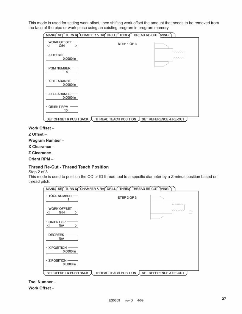
This mode is used for setting work offset, then shifting work offset the amount that needs to be removed from the face of the pipe or work piece using an existing program in program memory.
GROOVINGMANUALSETUP
SET OFFSET & PUSH BACK THREAD TEACH POSITION SET REFERENCE & RE-CUT
TURN & FACE
WORK OFFSETG54
Z OFFSET
PGM NUMBER0
X CLEARANCE0.0000 in
STEP 1 OF 3
Z CLEARANCE0.0000 in
ORIENT RPM10
CHAMFER & RADIUSDRILL & TAPTHREADINGTHREAD RE-CUT
0.0000 in
Work Offset – Z Offset – Program Number –X Clearance – Z Clearance – Orient RPM –
Thread Re-Cut - Thread Teach PositionStep 2 of 3This mode is used to position the OD or ID thread tool to a specific diameter by a Z-minus position based on thread pitch.
SET OFFSET & PUSH BACK THREAD TEACH POSITION SET REFERENCE & RE-CUT
TOOL NUMBER
G54WORK OFFSET
ORIENT SP
DEGREES
STEP 2 OF 3
X POSITION0.0000 in
Z POSITION
1
N/A
N/A
0.0000 in
GROOVINGMANUALSETUPTURN & FACECHAMFER & RADIUSDRILL & TAPTHREADINGTHREAD RE-CUT
Tool Number – Work Offset –

ES0609 rev D 4/09 28
Orient SP –Degrees – X Position – Z Position –
Thread Re-Cut - Set Reference & Re-CutStep 3 of 3This mode is used to teach the threading tool OD or ID. Then re-cut the threads using an existing program in program memory.
SET OFFSET & PUSH BACK THREAD TEACH POSITION SET REFERENCE & RE-CUT
REFERENCE
0PGM NUMBER
X CLEARANCE
Z CLEARANCE
STEP 3 OF 3
X TOOL WEAR0.0000 in
Z OFFSET
NOT SET
0.0000 inORIENT RPM
10
0.0000 in
0.0000 in
GROOVINGMANUALSETUPTURN & FACECHAMFER & RADIUSDRILL & TAPTHREADINGTHREAD RE-CUT
Reference – Program Number – X Clearance –Z Clearance – X Tool Wear – Z Offset – Orient RPM –
Grooving Mode - OD GrooveThis mode is for an outside diameter groove.

ES0609 rev D 4/09 29
MANUALSETUPTURN & FACE
Press <CYCLE START> to runin MDI or <F4> to recordoutput to a program
CHAMFER & RADIUSDRILL & TAPTHREADING
TOOL NUMBER1
WORK OFFSET54
Z START PT0.0000 in
OUTSIDE DIA.0.0000 in
OD GROOVE ID GROOVE PART OFF PART OFF WITH PECK
DIA. TO CUT0.0000 in
0.0000 in
0.0000 in
TOOL WIDTH0.0000 in
MAX RPM1000
Z DIMENSION
GROOVE WIDTH
FEED PER REV0.0000 in
200SFM
THREAD RE-CUTGROOVING
Tool Number – Enter the tool to be used.Work Offset – Enter the work offset to be used.Z Start PT – Enter the Z axis starting point.Outside Dia – Enter the current diameter of the work piece. Manually measure the diameter.Dia to Cut (Diameter to Cut) – Enter the finished diameter.Z Dimension – Enter the Z-axis dimension of the groove. Entered value must be positive.Groove Width – Enter the finished width of the groove. Entered value must be positive.Tool Width – Enter the actual width of the tool.Feed per Rev – Enter the feed per revolution.MAX RPM – Enter the maximum spindle turning speed.SFM – Enter the Surface Feed per Minute.Advanced Users: Additional Settings may need to be modified to create the required groove. These setting numbers are: 22, 28, 72, 73, 86. See the definitions of the setting in the Operator’s Manual.In the full CNC mode this is a G75 command.
Grooving Mode - ID GrooveThis mode is for an outside diameter groove.

ES0609 rev D 4/09 30
Press <CYCLE START> to runin MDI or <F4> to recordoutput to a program
OD GROOVE ID GROOVE PART OFF PART OFF WITH PECK
TOOL NUMBER1
WORK OFFSET54
Z START PT0.0000 in
INSIDE DIA.0.0000 in
DIA. TO CUT0.0000 in
0.0000 in
0.0000 in
TOOL WIDTH0.0000 in
MAX RPM1000
Z DIMENSION
GROOVE WIDTH
FEED PER REV0.0000 in
200SFM
MANUALSETUPTURN & FACECHAMFER & RADIUSDRILL & TAPTHREADINGTHREAD RE-CUTGROOVING
Tool Number – Enter the tool to be used.Work Offset – Enter the work offset to be used.Z Start PT – Enter the Z axis starting point.Outside Dia – Enter the current diameter of the work piece. Manually measure the diameter.Dia to Cut (Diameter to Cut) – Enter the finished diameter.Z Dimension – Enter the Z-axis dimension of the groove. Entered value must be positive.Groove Width – Enter the finished width of the groove. Entered value must be positive.Tool Width – Enter the actual width of the tool.Feed per Rev – Enter the feed per revolution.MAX RPM – Enter the maximum spindle turning speed.SFM – Enter the Surface Feed per Minute.Advanced Users: Additional Settings may need to be modified to create the required groove. These setting numbers are: 22, 28, 72, 73, 86. See the definitions of the setting in the Operator’s Manual. In the full CNC mode this is a G75 command.
Grooving Mode - Part OffThis mode is for parting off.

ES0609 rev D 4/09 31
Press <CYCLE START> to runin MDI or <F4> to recordoutput to a program
OD GROOVE ID GROOVE PART OFF PART OFF WITH PECK
TOOL NUMBER1
WORK OFFSET54
Z START PT0.0000 in
OUTSIDE DIA.0.0000 in
DIA. TO CUT0.0000 in
0.0000 in
0.0000 in
FEED PER REV0.0000 in
SFM1000
PART LENGTH
TOOL WIDTH
MAX RPM0.0000 in
MANUALSETUPTURN & FACECHAMFER & RADIUSDRILL & TAPTHREADINGTHREAD RE-CUTGROOVING
Tool Number – Enter the tool to be used.Work Offset – Enter the work offset to be used.Z Start PT – Enter the Z axis starting point.Outside Dia. – Enter the actual diameter of the part. This is the current diameter of the workpiece. Manually measure the diameter.Dia. to Cut – (Diameter to Cut) – Enter the depth the tool is to cut into the part.
NOTE: Entering a negative value for “Dia to Cut” causes the tool to pass spindle center and machine the entire face of the part; Do Not enter a value larger than -.100”.
Part Length – Enter the finished part length. Entered value must be positive.Tool Width – Enter the parting tool width.Feed per Rev – Enter the feed per revolution. This is the distance the tool moves for each spindle revolution.MAX RPM – Enter the maximum spindle turning speed.SFM – Enter the Surface Feed per Minute.Advanced Users: In the full CNC mode this is a G01 command.
Grooving Mode - Part Off with PeckThis mode is for parting off with a peck.

ES0609 rev D 4/09 32
Press <CYCLE START> to runin MDI or <F4> to recordoutput to a program
OD GROOVE ID GROOVE PART OFF PART OFF WITH PECK
TOOL NUMBER1
WORK OFFSET54
Z START PT0.0000 in
OUTSIDE DIA.0.0000 in
DIA. TO CUT0.0000 in
0.0000 in
0.0000 in
FEED PER REV0.0000 in
PECK VALUE1000
PART LENGTH
TOOL WIDTH
MAX RPM0.0000 in
200SFM
MANUALSETUPTURN & FACECHAMFER & RADIUSDRILL & TAPTHREADINGTHREAD RE-CUTGROOVING
Tool Number – Enter the tool to be used.Work Offset – Enter the work offset to be used.Z Start PT – Enter the Z axis starting point.Outside Dia. – Enter the actual diameter of the part. This is the current diameter of the workpiece. Manually measure the diameter.Dia to Cut (Diameter to Cut) – Enter the depth the tool is to cut into the part.
NOTE: Entering a negative value for “Dia to Cut” causes the tool to pass spindle center and machine the entire face of the part; Do Not enter a value larger than -.100”.
Part Length – Enter the finished part length. Entered value must be positive.Tool Width – Enter the parting tool width.Feed per Rev – Enter the feed per revolution. This is the distance the tool moves for each spindle revolution.MAX RPM – Enter the maximum spindle turning speed.Peck Value – Enter the distance the tool will advance at each ‘PECK’.SFM – Enter the Surface Feed per Minute.Advanced Users: In the full CNC mode this is a G75 command.

ES0609 rev D 4/09 33
dXF FIle IMporter
This feature can quickly build a CNC G-code program from a DXF file, a drawing file format exportable from many desktop CAD applications. Compatible DXF files are made up of arcs, lines, circles, vertices, and/or points. Refer to your CAD application’s documentation for details on how to export a DXF file. When import-ing a DXF file, you define its features one by one as tool paths; G-code is generated for each tool path that can then be placed in any new or existing program. DXF Importer for lathes is used to create ID and OD part profiles, for other features (threads, etc.), use IPS.
IMportIng the dXF FIle
Note: Tools should be set up in IPS before starting this process.
1. Press LIST PROG, select the tab for the device (USB, Hard Drive, or Floppy) containing the DXF file and press Write/Enter. Use the cursor arrows to highlight the DXF file and press Write/Enter to select it.
2. Press F2 and select “memory”. The control will recognize the DXF file and import it into the editor.
Exit (F1)Zoom ON/OFF (F4)Prev Chain pt (LEFT)Next Chain pt (RIGHT)Select Point (UP/DOWN)Cancel Action (CANCEL)Select Group (PG UP/DN)Chng Line Width (ALTER)Delete Group (DELETE)Undo Group (UNDO)
X 0.0000Z 0.0000Type: STARTGroup: 0Chain: 0
EXTRA KEY COMMANDS
Enter Origin Point: Use one of the following and press the WRITE key:X: 0.0000 1) Jog to X and Z position on part. (Use jog axis keys)Z: 0.0000 2) Use up and down arrows to select point.
3) Enter X and Z coordinates.
INPUT:
CURRENT GROUPS
TEST.DXF
EDIT: EDIT
The DXF importer feature provides on-screen help in the lower right corner of the display. The keys needed are defined beside the steps. Additional keys are identified in the left hand column.
DXF Importer creates programs using simple input given in the following steps:
1. Set the part origin point2. Chain a tool-path3. Set the tool-path4. Repeat steps 2 and 3 for remaining features
Set the orIgIn poInt
Use one of three methods:
Point Selection - Use the up and down arrow keys to select a point.•
Jogging - Jog to the X and Z position on a part (use jog axis keys).•
Enter Coordinates - Type in X coordinate and press WRITE/ENTER, then type in Z coordinate and press • WRITE/ENTER.
ES0609 rev D 4/09 34
Exit (F1)Zoom ON/OFF (F4)Prev Chain pt (LEFT)Next Chain pt (RIGHT)Select Point (UP/DOWN)Cancel Action (CANCEL)Select Group (PG UP/DN)Chng Line Width (ALTER)Delete Group (DELETE)Undo Group (UNDO)
X 0.0000Z 6.1388Type: STARTGroup: 0Chain: 0
EXTRA KEY COMMANDS
Step Jog Step Size: 0.11. (ORIGIN) Chain Selection OFF2. Chain (F2)3. ToolPath (F3)
Origin
INPUT:
CURRENT GROUPS
TEST.DXF
EDIT: EDIT
Use the keys to choose a point to beginchaining. The red line represents the selectedline, the green line represents the directionof the cut. Hit to begin chaining.
UP/DOWN
F2
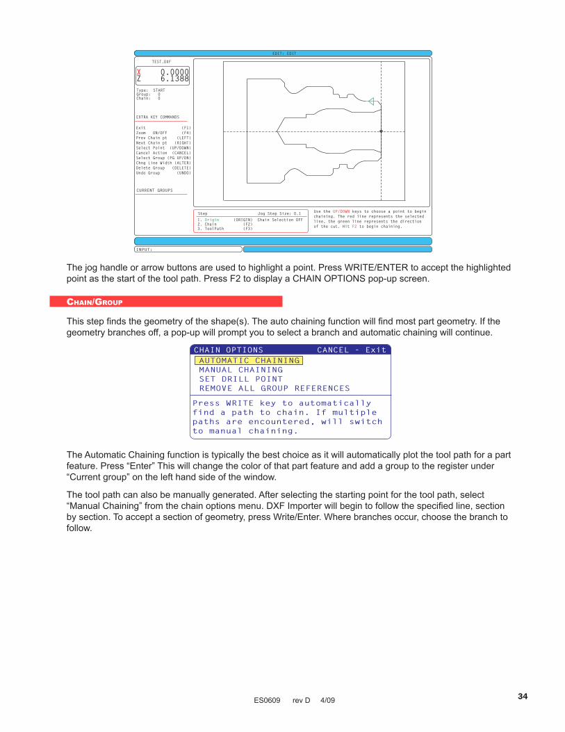
The jog handle or arrow buttons are used to highlight a point. Press WRITE/ENTER to accept the highlighted point as the start of the tool path. Press F2 to display a CHAIN OPTIONS pop-up screen.
chaIn/group
This step finds the geometry of the shape(s). The auto chaining function will find most part geometry. If the geometry branches off, a pop-up will prompt you to select a branch and automatic chaining will continue.
The Automatic Chaining function is typically the best choice as it will automatically plot the tool path for a part feature. Press “Enter” This will change the color of that part feature and add a group to the register under “Current group” on the left hand side of the window.
The tool path can also be manually generated. After selecting the starting point for the tool path, select “Manual Chaining” from the chain options menu. DXF Importer will begin to follow the specified line, section by section. To accept a section of geometry, press Write/Enter. Where branches occur, choose the branch to follow.

ES0609 rev D 4/09 35
Exit (F1)Zoom ON/OFF (F4)Prev Chain pt (LEFT)Next Chain pt (RIGHT)Select Point (UP/DOWN)Cancel Action (CANCEL)Select Group (PG UP/DN)Chng Line Width (ALTER)Delete Group (DELETE)Undo Group (UNDO)
X 0.0000Z 6.1388Type:Group:Chain:
START
11
EXTRA KEY COMMANDS
Step Jog Step Size: 0.11. (ORIGIN) Chain Selection OFF2. (F2)3. ToolPath (F3)
OriginChain
INPUT:
CURRENT GROUPSGroup 1 PROFILE OD
TEST.DXF
EDIT: EDIT
Use the jog handle to choose your rapid point,then hit WRITE.
Select tool path
This step applies a tool-path operation to a particular chained group. Select group and Press F3 to choose a tool path.
TOOL PATH OPERATION CANCEL - ExitPROFILE ODPROFILE ID
Creates a profile OD.
‘Select Rapid Point’ is displayed at the bottom of the screen. Use the jog handle to choose the rapid point and press WRITE/ENTER.
Step Jog Step Size: 0.11. (ORIGIN) Chain Selection OFF2. (F2)3. (F3)
OriginChainToolPath
INPUT:
TEST.DXF
Steps complete. Use the keys to choosea point to begin chaining. Hit to repeattoolpath operation, or to delete thisgroup.
UP/DOWNF3
F2
Exit (F1)Zoom ON/OFF (F4)Prev Chain pt (LEFT)Next Chain pt (RIGHT)Select Point (UP/DOWN)Cancel Action (CANCEL)Select Group (PG UP/DN)Chng Line Width (ALTER)Delete Group (DELETE)Undo Group (UNDO)
Type:Group:Chain:
START
11
EXTRA KEY COMMANDS
EDIT: EDIT
Enter the number of the profile touse, press ENTER to open shape selector press F1 key.
Press to go back to the DXF editor.EDIT
X 9.1112Z 6.1388
CURRENT GROUPSGroup 1 PROFILE OD
GROOVINGTHREAD RE-CUTTHREADINGDRILL & TAPCHAMFER & RADIUSMANUALSETUP
RAPID FEED OD TURN FACE
CHAMFERTURN & FACE
ID TURN PROFILE
Press <F4> to record outputto a program
TOOL NUMBER1
WORK OFFSET54
CUT TYPEHRZ TYPE II
X STOCK ALLOW0.0000 in
NUM OF PASSES
X DISTANCE
Z DISTANCE
FEED PER REV0.0100 in
SPINDLE DIR
CUTTER COMP
COOLANT
MIRROR X
Z STOCK ALLOW0.0000 in
DEPTH OF CUT0.0050 in
MAX RPM1000
SFM10
GRAPHIC MODE
PROFILE NUMBR1
FORWARD
OFF
OFF
OFF
OFF
N/A
N/A
N/A
Once a tool-path is selected, the IPS (Intuitive Programming System) template for that shape is displayed. Most IPS templates are filled with reasonable defaults derived from tools and materials that have been setup.
Press F4 to save the toolpath once the template is completed. Refer to the “IPS Recorder” section for details on saving the path into a new or existing program.
Press Edit to return to DXF Editor.

ES0609 rev D 4/09 36
IpS recorder
The IPS recorder provides a simple method to place G-code generated by IPS into new or existing programs.
1. To access IPS, press MDI/DNC, then PROGRM/CONVRS. Refer to your Intuitive Programming System Operator Manual (ES0609 Lathe) for more information on using IPS.
2. When the recorder is available, a message appears in red in the lower right corner of the tab:
VQCGROOVINGTHREADINGDRILL & TAPMANUAL CHAMFER AND RADIUS
TOOL NUMBER
WORK OFFSET
Z START PT
DIA TO CUT
Z DIMENSION
DEPTH OF CUT
MAX RPM
SFM
1 1000
54 0.0000 in 200
0.0000 in 0.0500 in
RAPID
Press <CYCLE START>to run in MDI or <F4>to record output to aprogram.
SETUP TURN & FACE
FILLET RADII0.0000 in
OUTSIDE DIA. FEED PER REV0.0000 in 0.0100 in
TOOL NOSE0.0315 in
0.0000 in
FEED OD TURN ID TURN FACE PROFILE
3. Press F4 to access the IPS recorder menu. Choose menu option 1 or 2 to continue, or option 3 to cancel and return to IPS. F4 can also be used to return to IPS from any point within IPS recorder.
IPS Recorder Menu
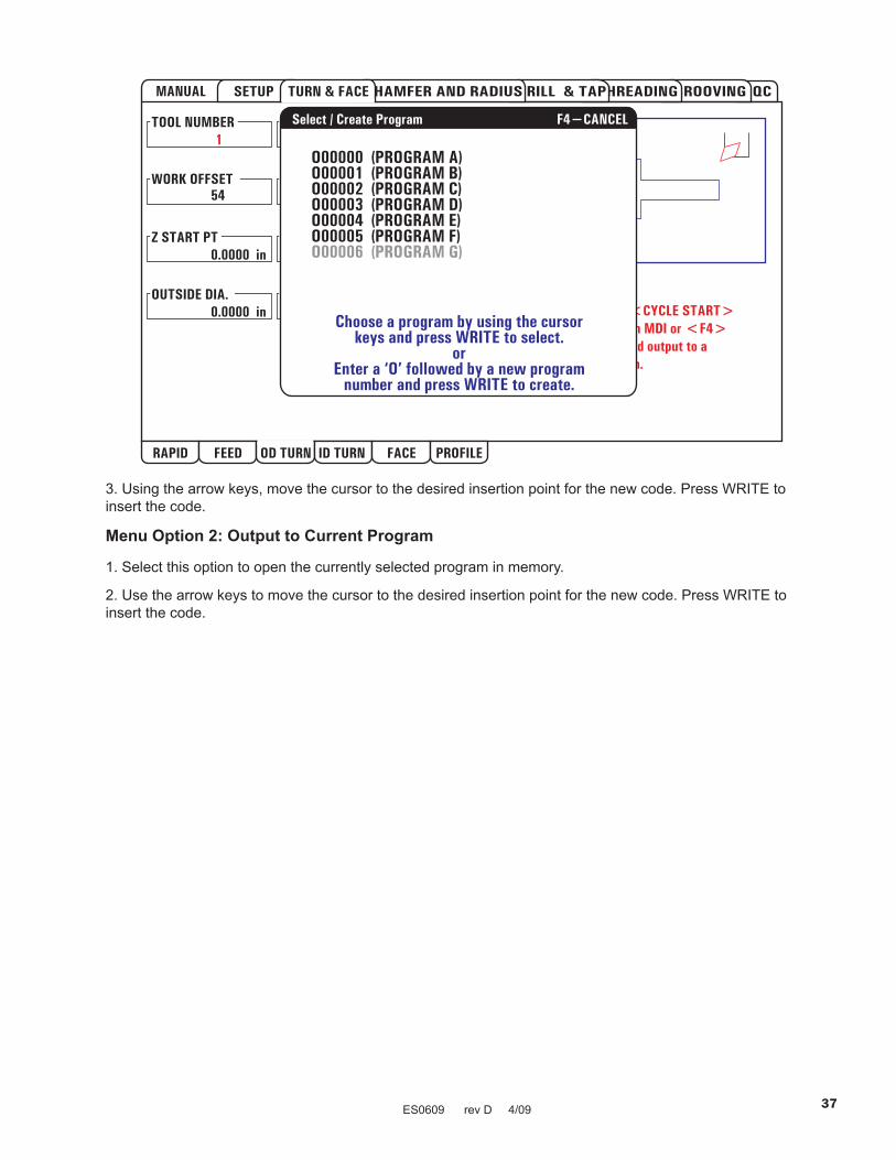
Menu Option 1: Select / Create ProgramSelect this menu option to choose an existing program in memory or to create a new program into which the G-code will be inserted.
1. To create a new program, input the letter ‘O’ followed by the desired program number and press the WRITE key. The new program is created, selected, and displayed. Press the WRITE key once more to insert the IPS G-code into the new program.
2. To select an existing program, enter an existing program number using the O format (Onnnnn), then press the WRITE key to select and open the program. To choose from a list of existing programs, press the WRITE key without input. Use the cursor arrow keys to choose a program and press WRITE to open it.
ES0609 rev D 4/09 37
3. Using the arrow keys, move the cursor to the desired insertion point for the new code. Press WRITE to insert the code.
Menu Option 2: Output to Current Program
1. Select this option to open the currently selected program in memory.
2. Use the arrow keys to move the cursor to the desired insertion point for the new code. Press WRITE to insert the code.

ES0609 rev D 4/09 38
operator Keyboard
The keyboard is broken up into eight sections: Function Keys, Jog Keys, Override Keys, Display Keys, Cur-sor Keys, Alpha Keys, Mode Keys and Number Keys. In addition there are miscellaneous keys and features located on the pendant.
SHIFT
/ [ ]
& @ :
%
*
+
$
,
=
!
?
#
PARAM SETNGGRAPH
HELPCALC
NEXTTOOL Z
X ZFACEMESUR
DIAMESUR
MESGSALARM
DGNOS
POSIT OFFSET COMDSPRGRMCONVRS
DISPLAYCURNT
OVERRIDES
CURSOR
PAGE
CHIP
CHIP
CHIPTS
TS
TS
RAPID STOP
FWD
REV
7 8 9
4
1
-
CANCEL
5
2
0
SPACE
6
3
WRITEENTER
SHIFT EDCBA
K
Q
W
)
J
P
V
(
I
O
U
EOB
H
N
T
Z
G
M
S
Y
F
L
R
X
-10 100% +10
FWD STOP REV
FEED RATE FEED RATE FEED RATE
-10 100% +10SPINDLE SPINDLE SPINDLE
RAPID5%
RAPID RAPID RAPID25% 50% 100%
INSERT ALTER DELETE UNDO
SINGLE DRY OPTION BLOCKBLOCK RUN STOP DELETE
COOLNT JOGTURRET TURRETFWD REV
.0001 .001 .01 .1.1 1. 10. 100.
ALL ORIGIN HOMEG28
SELECT SEND RECV ERASEPROG PROG
SINGL
EDIT
MEM
MDIDNC
HAND
ZERO
LIST
JOG
RET
PROG
F1 F2 F3 F4
POWERUP
RESTARTAUTO
-X
+X
-Z +ZRAPID
OFF
X SPINDLE
UPHOME
END DOWNPAGE
SPINDLE
SPINHANDCNTRL
RESET
FEEDHANDCNTRL