introduction - welcome to board of intermediate … · afterwards by the method of triangulation or...
TRANSCRIPT

Structure1.1 Concept of Surveying
1.2 Purpose of Surveying
1.3 Linear and Angular measurements
1.4 Classification of Surveying
1.5 Reconnaissance, Preliminary location survey, final location survey
Learning ObjectivesAfter studying this unit, the student will be able to
• Understand what is surveying
• Purpose and principles of suveying
• Types of Surveying
• Conversion of linear measurements from one system to other System
1.1 Concept of SurveyingSurveying is the art of determining the relative positions of different features
on, above or beneath the earth’s surface by taking measurements in the horizontaland vertical planes. Surveying is usually considered as a process of determining
Introduction
1UNIT

Construction Technology194
relative positions of different points in horizontal plane. Leveling is consideredas a process of determining relative positions of points in vertical plane.
Fundamental principles of surveying
The two fundamental principals of surveying are
a) To locate a new station by measurements from at least two referencepoints.
b) To work from whole to part.
a) Locating a new station. It is always practicable to select two points inthe field and to measure the distance between them. These can be representedon paper by two points placed in a convenient position. From these referencepoints other points can be located by two suitable measurements in the field anddrawn in their relative positions on the sheet.
The common methods of locating a point such as C with respect to tworeference points such as A and B are illustrated in Fig.1.1
Fig.1.1
(a) Distances AC and BC are measured, and C is plotted as the intersectionpoint of two arcs with centers A and B and radii from the measured distances.
(b) Perpendicular CD and distance AD or BD measured and C is plottedby the use of a set square.
(c) Distance AC and the angle BAC are measured, and C is plotted bymeans of a protractor.
(d) Angles ABC and BAC are measured, and C is plotted by a protractoror by solution of triangle ABC.
Paper - II Surveying Theory 195
(e) Angle BAC and distance BC are measured, and C is plotted by aprotractor.
One or more than one of the above methods may be used in the samesurvey according to the instruments available and purpose of survey.
b) Working from whole to part. In surveying an area, it is essential toestablish a system of control points with great accuracy. Minor control pointscan then be established by less accurate methods and the details can be locatedafterwards by the method of triangulation or traversing between the controlpoints. This way the minor errors are automatically controlled and localized anddo not accumulate. On the other hand, if we work from part to the whole, thesmall errors are magnified and become uncontrollable at the end.
1.2 Purpose of SurveyingThe main purpose of surveying is to prepare a plan or map of the areas.
Surveys are required before and during the planning and construction of workssuch as highways, buildings, bridges, canals etc.
The surveyor has to perform the following functions.
1. Recording measurements in the field.
2. Making necessary calculations to determine areas, volumes etc.
3. Plotting the measurements and drawing a map.
4. Setting out structures.
1.3 Linear and Angular MeasurementsIn surveying, a surveyor has to generally deal with linear and angular
measurements both in horizontal and vertical planes. Linear measurements takenin the horizontal plane are horizontal distances whereas those taken in the verticalplane are called vertical distances. Similarly the angular measurements arehorizontal angles and vertical angles when taken in the horizontal and verticalplanes respectively.
Linear measurements: The unit of length is a meter in M.K.S systemand a foot in F.P.S system .The units of length, area and volume in metric systemand their conversion to F.P.S. system are given in the following tables.

Construction Technology196
Table1.1. Units of Length
10 millimeters (mm) 1 centimeter (cm)
10 centimeters (cm) 1 decimeter (dm)
10 decimeters (dm) or 100 cm 1 meter (m)
10 meter (m) 1 deca meter (dam)
10 decameter (dam) or 100m 1 hecta meter (hm)
10 hectometers (hm) or 1000m 1 kilo meter (km)
Conversion: 1 inch = 2.54 cm
1 foot = 0.3048m
1 mile = 1.6093km
Table1.2 Units of Area
100 sq.mm = 1 sq.cm
100 sq.cm = 1 sq.dm
100 sq.dm = 1 sq.m
100 sq.m = 1 Are(a)
100 Ares = 1 Hectare
100 Hectares = 1 sq.km.
Conversion: 1 Sq. inch = 6.4516 Sq. cm
1 Sq. ft = 0.0920 Sq.m
1 Sq. mile = 2.59 Sq.km
1 acre = 0.4047 hectare
=
=
=
=
=
=

Paper - II Surveying Theory 197
Table1.3Units of volume
1000 Cu.mm = 1Cu.cm
1000 Cu.cm = 1Cu.dm
1000 Cu.dm = 1 Cu.m
Conversion: 1 cu inch = 16.387 cu cm.
1 cu feet = 0.0283 cu. m
Angular Measurements: A radian is the unit of plane angle and is equalto the angle subtended at the centre of a circle by an arc equal in length to itsradius.
radians = 2 right angles
1 right angle = 100 grades or 90o.
A degree is the basic unit of angle used in India.
1 degree(o) = 60 minutes(,)
1 minute(,) = 60 seconds(,,)
1.4 Classification of SurveyingSurveys are classified according to
1) Instruments used.
2) Purpose of survey
3) Methods employed.
4) Nature of the field.
1. Classification Based on instruments used.
Based on instruments used the surveys are classified as follows.
a) Chain survey
b) Compass survey
Construction Technology198
c) Plane table survey
d) Leveling
e) Theodolite survey
f) Tachometric survey.
2. Classification based on purpose of survey
a) Mine surveys to explore the mineral wealth.
b) Geological surveys to determine different strata in the earth’s crust.
c) Archeological surveys to trace relics of the past.
d) Military surveys to prepare maps of military importance.
3. Classification according to the method employed
a) Triangulation Survey
b) Traverse survey.
4. Classification according to nature of the field.
a) Land surveys for objects on earth’s surface.
b) Marine surveys for objects under water
c) Astronomical survey for observations of heavenly bodies.
Land Surveys are further classified into following types
a) Topographical surveys.
b) Cadastral surveys
c) City surveys
a) Topographical surveys: These surveys are performed for determiningthe natural features of the country like lakes, rivers, hills etc. and also the artificialfeatures like roads, canals, towns, villages, etc.
b) Cadastral surveys: These surveys are similar to topographical surveyexcept that additional details such as boundaries of fields, houses are alsodetermined.
c) City surveys: These surveys are carried out for laying of plots,construction of roads, sewer lines, water supply system etc.

Paper - II Surveying Theory 199
1.41. Plane and Geodetic Surveying.
The surveying is mainly divided into following two types
a) Plane surveying.
b) Geodetic surveying.
a) Plane surveying: Surveying in which the effect of curvature of theearth is not considered is known as plane surveying. It is applicable for smallareas only.
b) Geodetic surveying: Surveying in which the curvature of the earth isconsidered is known as geodetic surveying. It is applicable to large areas andsurveys where greater precession is required.
1.4.2. Classification based on instruments.
Based on instruments used the surveys are classified as follows.
a) Chain survey
b) Compass survey
c) Plane table survey
d) Leveling
e) Theodolite survey
f) Tachometric survey.
1.4.3. Engineering Surveys
These surveys are carried out in connection with engineering works suchas roads, railways, reservoirs and works connected with water supply.
1.5 Reconnaissance, Preliminary Location Survey, Final Location SurveyEngineering surveys are further sub divided into
a) Reconnaissance survey.
b) Preliminary location survey.
c) Final location survey.
a) Reconnaissance survey: Reconnaissance survey is the physicalobservation of the area for determining the feasibility of work, and to knowrough cost of the work.

Construction Technology200
b) Preliminary location survey: In this survey more precise data iscollected to select the best location for the work and to estimate the exactquantities and costs.
c) Final location survey: final location surveys are carried out for settingout the works on the ground surface.
Summary1. Surveying is the art of determining the relative positions of different
points on the earth’s surface in horizontal plane.
2. In plane surveying the curvature of the earth is not considered.
3. In Geodetic surveying the curvature of the earth is considered
4. Surveys are classified based on
(a) Instruments (b) Purpose of survey
(c) Methods employed (d) Nature of the field.
5. Topographical survey is performed for determining the naturalfeatures like lakes, rivers, hills etc and also the artificial features likeroads, canals etc.
6. Reconnaissance survey is the physical observation of the area fordetermining the feasibility of work.
Short Answer Type Questions1. Define Surveying
2. What is reconnaissance survey?
3. Write the types of land surveys
4. Define Plane Surveying
5. Define Geodetic Surveying
6. What is preliminary location survey?
7. What is final location survey?
Long Answer Type Questions1. Explain purposes of surveying
2. Explain classification of surveying.

Paper - II Surveying Theory 201
3. Explain the fundamental principles of Surveying.
Activity• With the help of a tape, measure sides of a rectangular room and calculate
area of the room.

Construction Technology202
Learning ObjectivesAfter studying this unit, the student will be able to understand
• Chain surveying and purpose of the equipment
• Studying the metric chain and reading the length.
• Types of survey stations and survey lines and their purpose
• Conventional signs used in chain surveying and recording fieldnotes in the field book.
• Various types of obstacles we need to overcome in the process ofmeasuring distance between two points.
• Methods of calculating area of a given piece of land with irregularboundary.
2.0 IntroductionChain surveying is the simplest and the most accurate kind of surveying. In
this the area is divided into network of triangles since the triangle is the onlyfigure which can be plotted without any angular measurements. Chain surveyingis adopted in the following situations.
1) When the ground is flat and with simple details.
Chain Surveying
2UNIT

Paper - II Surveying Theory 203
2) When the area to be surveyed is small.
3) When large scale mapping is desired.
2.1 Purpose and Principle of Chain SurveyChain surveying has the following purposes.
1) To collect necessary data for exact description of the land.
2) To calculate the area of the plot
3) To prepare the plan of the site
4) To demarcate the boundaries of the land
5) For division of land into smaller units.
Principle of chain surveying:
The triangle is the simplest figure that can be plotted from the lengths of itssides. Based on this, the principle of the chain surveying is to divide the area intoa network of well conditioned triangles. The error will be least in plotting atriangle is when no angle of the triangle is less than 300 and more than 120o.Such triangles are called well conditioned triangles. Chain surveying is also calledas chain triangulation.
2.2. Equipments Used in Chain Surveying and their Functions .
The following equipments are used in chain surveying
1) Chain
2) Tape
3) Ranging rod
4) Offset rod
5) Cross staff
6) Arrows
7) Pegs
8) Plumb bob etc.
1. Chain: This is an instrument used for measuring distance. There are fourtypes of chains.

Construction Technology204
i) Metric chain.
ii) Engineer’s Chain.
iii) Gunter Chain.
iv) Revenue chain.
(i) Metric chain: In metric system the chains of 20m and 30m arecommonly used. The chain is made with galvanized steel wire of 4mm diameter.Each meter is divided into 5 links of 20mm length. It is provided with brasshandles on either ends. The tallies are fixed at every 5m length and small brassrings are provided at every meter length. The chain is shown in the fig 2.1.
Fig. 2.1
(ii) Engineer’s chain: The Engineer’s chain is 100ft length and made of100 links.
(iii) Gunter chain: It is 66 feet long and having 100 links. It is useful formeasuring the distance in miles and areas in acres. 10 square Gunter chain =1 acre = 4840 sq. yards.
(iv) Revenue chain: This chain is of 33ft length and is divided into 16links.

Paper - II Surveying Theory 205
2. Tape: The tapes are divided according to the materials used as following
(i)) Metallic tapes (ii) Steel tapes (iii) Invar tapes
(i) Metallic tapes: This tape is made with water proof linen with brass,copper wires to avoid stretching. The tapes availablein lengths 2, 5, 10, 20 and 30m.
(ii) Steel tapes: This is most accurate tape for takingmeasurements. If carelessly handled it gets broken.
(iii) Invar tapes: If the measurements are to be madewith highest precision this tape is used. These are 6mmwide and available in lengths of 30, 50 and 100m.
3. Ranging rods: Theses are wooden or metal poles2m or 3m long and having a diameter of 30mm. Theyare provided with iron shoes at the lower ends tofacilitate easy driving in the ground. They are paintedin bands alternatively in black and white or red andwhite. Ranging rods used for ranging a line.
4. Offset rods: This is mainly used to measure offsetsof shorter lengths. It is usually 2m long.
5. Cross staff: Cross staff is an instrument used forsetting perpendicular offsets. These are three types.
i) Open cross staff
iii) Adjustable cross staff
iii) French cross staff
(i) Open cross staff: It consists of 4 metal arms at right angles to eachother having eye vane at two adjacent ends and object vane at the other ends.
(ii) Adjustable cross staff: With this cross staff the object can be set atany angle.
(iii) French cross staff: This cross staff is an octagonal brass tube withslits on its eight faces. With this cross staff we can set the object at an angle of450 also.
Fig. 2.2 Ranging rod
Fig. 2.3 Open Cross Staff

Construction Technology206
Fig. 2.4 French Cross Staff
Optical Square: This is an instrument used for setting out right angles tothe chain lines and to find out the foot of the perpendicular on the chain line froman object. It works on the principle of reflection.
6. Arrows: These are used for marking the ends of a chain during theprocess of chaining. These are steel pins 400mm long and are pointed at oneend.
Fig. 2.5 Arrows
7. Pegs: These are made from hard timber and tapered at one end. Thelengths varies from 120 to 600mm. these are driven into ground to mark theinstrument stations.
8. Plumb bob: It is used to define the vertical line while measuring distancealong slopes.
2.3 Coventional SignsConventional signs are symbols of objects represented on a map or in the
field book.
Some of the common conventional signs used in chain surveying are givenin fig.2.15.
4mm Thick
15mm Normal400mm +- 5mm
Paper - II Surveying Theory 207
2.4. Errors in ChainingErrors will be introduced in chaining due to the following reasons.
a). Instrumental errors: these are due to defective conditions ofinstrument. E.g. a chain may be either too long or too short.
b). Natural errors: These are due to variations in the natural phenomenae.g. changes in length due to temperature.
2.5. Correction Due to Incorrect Length of the Chain or Tape
If a chain has been damaged and it may be too short or too long of the truelength of the chian, and all the measurements taken will be too long or too short,conversely a contracted or stretched chain will give incorrect measurements ofthe true lengths.
The correct lengths of a measured distance is found from
where L’ = Incorrect length of chain or tape
L = Correct length of chain or tape
Or Correct Length = Measured Length x L’
L
Correct Length = Measured Length x Incorrect length of chainCorrect length of chain
If an area has been calculated then,
Correct area = Calculated area x
If an volume has been calculated then,
Correct volume = Calculated volume x Incorrect length of chain
Correct length of chain
3
Incorrect length of chainCorrect length of chain
2

Construction Technology208
Example 2.1: A 30m chain was found to be 10cm too long after chaininga distance of 1360m. Find the true distance.
Correct length of the chain = 30m
Incorrect length of the chain = 30 + 0.10 = 30.10
Measured distance = 1360m
Example 2.2 : A road actually 1330 m long was found to be 1326 m whenmeasured with a defective 30 m chain. How much correction does the chainneed. ?
Solution :
True length = Measured length x L’ / L
True length = 1330 m
Measured Length = 1326 m
Length of the chain = 30 m.
1330 = 1326 x L’ / 30
The chain is 0.09 m (9cm) too long
Correction = -9 cm (Ans).
Example 2.3 : A 20 m chain was found to be 6 cm too long at the end ofthe days work after measuring 6000 m. If the chain was correct before thecommencement of the work, find the correct length of the line.
Solution : The increase of 6 cm should be taken as gradually.
mean in correct length of the chain L’ = 20+(20.06/2) = 20.03 m.
True distance = Measured distance x Incorrect length of chainCorrect length of chain
1360 x = 1364.53 m30.1030.00
True length = Measured length x Incorrect length of chainCorrect length of chain
L’ = = 30.09 m1330 x 30 1326
Paper - II Surveying Theory 209
Correct length of the chain , L = 20m. Measured Distance = 6000 m
True distance = 6000 x 20.03 /20 = 6009 m(Ans).
Example : 2.4 : A 30 m chain was found to be 6 cm too long after chaininga distance of 4000 m. It was tested again at the end of day’s work and found tobe 8 cm too long after changing a total distance of 7800 m. If the chain wascorrect before the commencement of the work, find the true distance.
Solution : Chain length before commencement of the work = 30 m
Chain length after measuring 4000 m = 30.06 m.
Mean incorrect length of the chain (L’) = (30 + 30.06) / 2 = 30.03 m.
True distance = Measured distance x L’ / L
True distance = 4000 x (30.03)/30 = 4004 m .................. (i)
Remaining distance measured after measuring 4000 m
= 7800 - 4000 = 3800 m
The distance of 3800 m was measured with the chain which was 6 cm toolong in the begining and 8 cm too long at the end of the chaining.
L’ = (30.06 + 30.08)/2 = 30.07 m
True distance = 3800 x (30.07) / 30 = 3808.9 m ...............(ii)
Total True distance = (i) + (ii)
= 4004 + 3808.9 = 7812.9 m (Ans)
Example : 2.5 : A metalic tape originally 20 m is now found to be 20.2 mlong. A house 40 m x 30 m is to be laid out. What measurement must be madeusing this tape ? What should the diagonal read ?
Solution : True distance = distance to be measured x L’ / L
L ‘ = 20.2 m
L = 20 m
40 = Length to be measured x (20.2 / 20)
Length to be measured = 40 x (20/20.2) = 39.6 m
Similarly, breadth to be measured = 30 x (20 / 20.2) = 29.7 m

Construction Technology210
Hence measurements to be made with 20.2 m tape instead of 20 m tapeare 39.6 m x 29.7m (Ans).
Diagonal measurement = (39.6)2 + (29.7)2
= 1568.16 + 882.09
= 2450.25 = 49.50 m (Ans).
Example 2.6 : A field was surveyed by a chain and the area was found tobe 228.30 sq.m. If the chain used in the measurement was 0.6 percent too long.What is the correct area of the field ?
Solution : True area = Measured Area x (L’/L)2
Measured area = 228.30 sq.m
L’ = 100 + 0.6 = 100.6 units.
L = 100 units.
True area = 228.30 x (100.6/100)2
= 231.05 Sq.m (Ans).
2.6 Types of Survey Lines These are the lines joining the main survey stations following are the types
of survey lines.
i) Base line
ii) Tie line
iii) Check line
2.6.1 Base Line : A line which is generally longest of all the survey linesand upon which the entire frame work is built up is known as a base line. Itgenerally runs in the centre of the area to be surveyed and should laid off on thelevel ground.
2.6.2. Tie Line : A line joining two Tie stations is known as a Tie line. It isrun to take the interior details which are far away from the main lines and also toavoid long offsets.
2.6.3. Check Line : A line which is used to check or prove the accuracyof the frame work as well as the plotting work is known as the check line. It is aline which runs from apex of a triangle to any other fixed points on any two sidesof a triangle.

Paper - II Surveying Theory 211
Fig. 2.6
2.7. Types of Survey StationsThe beginning and end of a chain line is called survey station. There are two
types of survey stations.
a) Main survey station b) Tie station or Subsidiary station.
a) Main survey station: These are important points at the beginning andat the end of the chain lines.
b) Tie station: These are points selected on the main survey lines forlocating the interior details.
2.8 Fixing of Survey StationsThe following points should be kept in mind while fixing a survey station
1) Main stations should be located on plane ground and should be mutuallyvisible.
2) The fundamental principle of surveying i.e. working from whole to partshould be observed. A long line should be laid across and other triangles shouldbe built on it.
3) The network should consist only well conditioned triangles.
4) Long offsets should be avoided.

Construction Technology212
5) The number of survey lines is to be made minimum as far as possible.
6) Survey stations should not be fixed on thoroughfares.
2.9. Different Operations in Chain Surveying2.9.1. Ranging : In measuring the length of a survey line, it is necessary
that the chain should be laid on the ground in a straight line between the endstations. If the line is short, it is easy to put the chain in true alignment. But if theline is long, it is necessary to place intermediate ranging rods to maintain thedirection. Fixing of intermediate points in a straight line between the two endstations is known as ranging.
Ranging is of two types: a) Direct ranging b) Indirect ranging.
(a) Direct Ranging
Direct ranging is adopted when the two end stations are mutually visible.The ranging is carried out by an eye or a line ranger.
Ranging by Eye
The ranging by eye is done by the following steps.
1) Fix ranging rods at each end of the line.
2) Stand about 1.5m beyond the first ranging rod.
3) Direct the assistant to hold the ranging rod vertically where the intermediatepoint to be fixed.
4) Direct the assistant to move left or right using code of signals until thethree ranging rods are in straight line.
5) Check the verticality of the rods by sighting the lower ends of the rods.
6) As and when the intermediate point is in straight line, signal the assistantto fix the ranging rod.
The following code of signals may be used in directing the assistant intoline.
Rapid sweep with right hand – move rapidly to the right.
Rapid sweep with left hand – move rapidly to the left.
Slow sweep with right hand – move slowly to the right.
Slow sweep with left hand – move slowly to the left.

Paper - II Surveying Theory 213
Right arm extended – move continuously to right.
Left arm extended – move continuously to left.
Right arm up and moved to the right – plumb the rod to the right.
left arm up and moved to the left – plumb the rod to the left.
Both hands up and brought down – correct.
Both arms extended forward
horizontally and the hands depressed – fix the ranging rod in position.briskly.
Ranging by Line Ranger
Line ranger is an optical instrument used for fixing intermediate points on achain line. It consists of two right angled isosceles triangular prisms placed oneabove the other.
Fig. 2.7
For fixing an intermediate station P on the line AB, the observer stands asnear P as possible and holds the instrument at his eye level. Rays of light comingfrom the ranging rods at A and B are reflected by the upper and lower prismsrespectively and reach the eye. If the images of A and B are in separate lines asshown in fig (b), the observer moves a little perpendicular to AB such that bothimages will be in the same line as in fig(c).
The required position of P will be then exactly below the center of theinstrument. One of two prisms can be adjusted by a screw. To test the instrumentit is held at the mid point of a line and the ranging rods at the end station observed.If both rods appear in the same line, the instrument is in adjustment. Otherwise,the fixing screw of the movable prism is slackened and the prism slightly rotatedso that both ranging rods appear in one line. Then the prism is fixed by tighteningthe fixing screw.
Construction Technology214
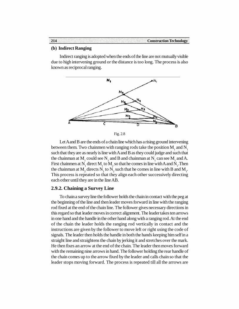
(b) Indirect Ranging
Indirect ranging is adopted when the ends of the line are not mutually visibledue to high intervening ground or the distance is too long. The process is alsoknown as reciprocal ranging.
Fig. 2.8
Let A and B are the ends of a chain line which has a rising ground interveningbetween them. Two chainmen with ranging rods take the position M1 and N1such that they are as nearly is line with A and B as they could judge and such thatthe chainman at M1 could see N1 and B and chainman at N1 can see M1 and A.First chainmen at N1 direct M1 to M2 so that he comes in line with A and N1.Thenthe chainman at M2 directs N1 to N2 such that he comes in line with B and M1.This process is repeated so that they align each other successively directingeach other until they are in the line AB.
2.9.2. Chaining a Survey LineTo chain a survey line the follower holds the chain in contact with the peg at
the beginning of the line and then leader moves forward in line with the rangingrod fixed at the end of the chain line. The follower gives necessary directions inthis regard so that leader moves in correct alignment. The leader takes ten arrowsin one hand and the handle in the other hand along with a ranging rod. At the endof the chain the leader holds the ranging rod vertically in contact and theinstructions are given by the follower to move left or right using the code ofsignals. The leader then holds the handle in both the hands keeping him self in astraight line and straightens the chain by jerking it and stretches over the mark.He then fixes an arrow at the end of the chain. The leader then moves forwardwith the remaining nine arrows in hand. The follower holding the rear handle ofthe chain comes up to the arrow fixed by the leader and calls chain so that theleader stops moving forward. The process is repeated till all the arrows are
Paper - II Surveying Theory 215
fixed by the leader. The follower who collected all these arrows hands over toleader. The number of arrows in the hand of the follower shows number of chainlengths measured. In this way the whole length of a survey line is measured.
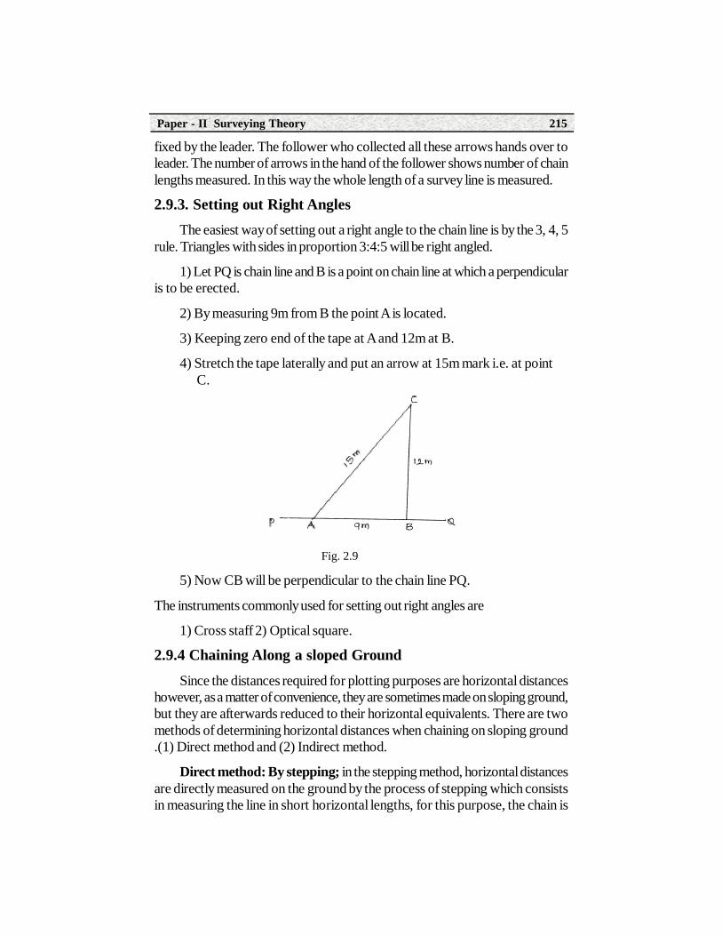
2.9.3. Setting out Right AnglesThe easiest way of setting out a right angle to the chain line is by the 3, 4, 5
rule. Triangles with sides in proportion 3:4:5 will be right angled.
1) Let PQ is chain line and B is a point on chain line at which a perpendicularis to be erected.
2) By measuring 9m from B the point A is located.
3) Keeping zero end of the tape at A and 12m at B.
4) Stretch the tape laterally and put an arrow at 15m mark i.e. at pointC.
Fig. 2.9
5) Now CB will be perpendicular to the chain line PQ.
The instruments commonly used for setting out right angles are
1) Cross staff 2) Optical square.
2.9.4 Chaining Along a sloped GroundSince the distances required for plotting purposes are horizontal distances
however, as a matter of convenience, they are sometimes made on sloping ground,but they are afterwards reduced to their horizontal equivalents. There are twomethods of determining horizontal distances when chaining on sloping ground.(1) Direct method and (2) Indirect method.
Direct method: By stepping; in the stepping method, horizontal distancesare directly measured on the ground by the process of stepping which consistsin measuring the line in short horizontal lengths, for this purpose, the chain is

Construction Technology216
stretched horizontally with one end resting on the ground at a convenient heightless than 1.8m and the point vertically below this end is then accurately found onthe ground by suspending a plumb bob and then marked. The next step is thencommenced from this point and the process is continued in correct alignmentuntil the end of the line is reached.
Fig. 2.10
The total horizontal distance PQ = PP1 + P2 P3 + P4Q1
Indirect Method: First Method : This method of stepping is not a veryaccurate method. The best way is to determine the land slope from the horizontalby using a Clinometer.
Fig. 2.11
Knowing the sloping distance say L and angle of slope say the horizontaldistance D = L Cos
Second Method : The distance along with the slope is measured withchain and the difference in the elevation between the first and the end stations isfound with the help of a levelling instrument (Fig. 2.12) knowing the slopingdistance l and the difference in the elevation h, the horizontal distance can befound from the relation, D = l2 - h2

Paper - II Surveying Theory 217
Fig. 2.12
Hypotenusal Allowance Method : Another method is to measure thedistance along the slope and apply a correction to get the horizontal distance.Let be the angle of the slope. Let AC be the distance measured along theslope and AC1 horizontal distance, 1chain or 100 links.
AC =100 Sec links. ThereforeCorrection BC = AC -AB = 100(sec -1) links per 100 link chain.
Fig. 2.13
This correction is known as the hypotenusal allowance. The leader mustplace the arrow ahead of his end of the chain on slopping ground by this amountso that the horizontal distance would be 1 chain.
Example 2.7 : The distance between two points A and B measured alonga slope is 504 m. Find the horizontal distance between A and B when (a) theangle of slope is 12o, (b) the slope is 1 in 4.5, and (c) the difference in elevationof A and B is 65m.
Solution : Let l = the distance measured along the slope between A and B.
D = the horizontal distance between A and B.
the angle of slope.
h
Construction Technology218
(a) l = 504 m, = 12o
then D = l cos 504 cos 12o= 504 x 0.9781
= 492.96 m (Ans.).
(b) The slope being 1 in 4.5 (i.e. 1 vertical to 4.5 horizontal)
Tan = 1/4.5 = 0.222 = 12o 32’
Hence D = l cos = 504 x cos 12o 32’
= 504 x 0.9762 = 492 m (Ans).
(c) l = 504, h = 65.
D = l2 - h2 = (504)2 - (65)2 = 499.80m (Ans).
Example 2.8 : Find the hypotenusal allowance per chain of 20 m length,the angle of slope of the ground is 10o.
Solution : Hypotenusal allowance = 100 ( Sec - 1)
= 100 (Sec 10o - 1) = 1.54 links
= 0.31 m. (Ans).
2.10 Principles Used in Chain TriangulationThe principle of the chain triangulation is to divide the area into a network
of well conditioned triangles. The error will be least when plotting a trianglewhen no angle of the triangle is less than 300 and more than 1200.Such trianglesare called well conditioned triangles. Chain surveying is also called as chaintriangulation.
2.11 Recording Field NotesField book: It is a book in which the field measurements and relevant
notes are recorded. It is about 200mm x 120mm in size and opens length wise.Each page is ruled with a single line or central column about 15mm wide runningup the long length of the pages. The pages of the field book are machinenumbered.
A specimen page of a field book is shown in the fig 2.14.
At the commencement of the line in the book is written (1) The name andnumber of the survey line.(2) The name, number of the station, and (3)Thesymbol denoting the station.

Paper - II Surveying Theory 219
Tie and subsidiary stations should be indicated by a circle or oval roundtheir chainage figures. Offsets written opposite of them on right or left of thecolumn.. As the work proceeds, the nature and form of the objects to whichoffsets are taken should be sketched with conventional signs and with nameswritten along them. The sketch is not drawn to scale.
The following points should be kept in view while booking the field notes:
Fig. 2.14
1) Each chain line should be started on a separate page.
2) The survey should always face the direction of chaining and allmeasurements should be recorded as soon as they are taken.
3) The notes should be complete and nothing should be left to memory.

Construction Technology220
4) Over writing and erasing of notes should be avoided. If any entry iswrong any change in the notes is necessary, a line should be drawnthrough it and a correct one written above it.
5) Explanatory notes and reference to other pages where ever necessaryshould be added.
6) Sketches of the various features located should be neat.
7) The complete record of the survey should include the following:
(i) Name of the survey (ii) Site of the survey (iii) The date of survey (iv) Thelength of the chain used and whether tested or not.(v) The rough sketch of thearea to be surveyed showing north direction, proposed stations, main and tielines etc.(vi) The names of the members of the party, and (vii) The page index ofthe chain lines and stations.
Conventional signs:
Fig. 2.15

Paper - II Surveying Theory 221
In chain surveying, while drawing maps or entering details of the objectsin field book symbols which are conventional are used to represent the objects.
Some of the common conventional signs used in surveying are given infigure above.
2.12. Obstacles in Chain SurveyingObstacles some times interfere with chaining. In such cases the obstructed
distances are found indirectly using the help of geometrical constructions.Obstacles may be classified into three categories.
1) Chaining free but vision obstructed
2) Chaining obstructed but vision free
3) Both chaining and vision are obstructed.
1. Chaining free but vision obstructed:
In this it is possible to move chain between the two end stations but theyare not visible to each other due to obstructions. There are two cases i) it is notpossible to see both ends from intermediate stations. Ex: a hillock in betweentwo stations.
ii) It is possible to see both the ends from any intermediate station.
Case (i): In this case, the problem may be overcome by indirect ranging.
Case (ii): This case occurs when a pond, a tree intervenes, preventing thefixing of intermediate stations. In this case random line method may be used. LetAB be the line whose length is required. Fig (2.16).From A run a line AB1called a random line, in any convenient direction. Chain the line to B from Amaking BB1 perpendicular to AB1 and measure BB1.
Then AB = AB12 + BB1
2
Intermediate points such as C can be located on the line AB by measuringAC1.
CC1 AC1
BB1 AB1
AC1
AB1
Fig. 2.16
=
x BB1CC1 =
Construction Technology222
Thus C can be located.
2. Chaining obstructed but vision free.
This is the case when a pond, river or plantations intervenes. Two convenientpoints have to be located on the chain line on either side of the obstacle and thedistance between them found.
There are two cases.
i) In which it is possible to chain round the obstacle e.g. a pond, a bend inthe river etc.
ii) In which it is not possible to chain round the obstacle, e.g. a river.
Case i): Several methods are available; however, a few are describedbelow.
Let AB be chain line and a pond intervenes.
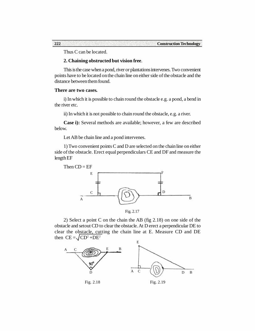
1) Two convenient points C and D are selected on the chain line on eitherside of the obstacle. Erect equal perpendiculars CE and DF and measure thelength EF
Then CD = EF
Fig. 2.17
2) Select a point C on the chain the AB (fig 2.18) on one side of theobstacle and setout CD to clear the obstacle. At D erect a perpendicular DE toclear the obstacle, cutting the chain line at E. Measure CD and DEthen CE = CD2 +DE2
Fig. 2.18 Fig. 2.19
A BC
D
E
A C D B
E
A BC D
E F

Paper - II Surveying Theory 223
3) Select two points C and D (fig 2.19) on either side of the obstacle. Setout perpendicular CE of length such that DE clears the obstacle. Measure CEand DE then.
CD = DE2 - CE2
Case ii): The typical example of this class of obstacle is a river. There areseveral methods, of which a few are given below.
Fig. 2.20
1) Select two points A and B (fig 2.20) on the chain line PR on oppositebanks of the river. Setout a perpendicular AD and bisect it at C. At D erect aperpendicular DE and mark the point E in line with C and B. Measure DE.Since the triangles ABC and CED are similar. AB = DE
2) As before select two points A and B. Fig (2.21). Set out a perpendicularAD at A. with cross staff erect a perpendicular to DB at D, cutting the chain lineat C. Measure AD and AC.
Since the triangles ABD and ACD are similar
AB AD
AD AC AC
Fig. 2.21
3. Chaining and vision both obstructed: In this case the problem consistsin prolonging the line beyond the obstacle and determining the distance across
= Hence , AD2AB =

Construction Technology224
it. A building is a typical example of this type of obstacle. Point C is chosen onthe chain line AB as near as possible to the building and rectangles EFGC,DHJK are setup on either side of the obstruction, JH is ranged in line with FG.Then EF= CG=DH=KJ, FGHJ is a straight line and GH = CD, the missingportion of the chain line AB.
Fig. 2.22
Example 2.9 : To continue a survey line A B to over come the obstacle aline BC 200 meters long was set out perpendicular to AB and from C anglesBCD and BCE were set out at 60o and 45o respectively. Determine the lengthswhich must be chained off along CD. Determine the obstructed length BE.
Solution :
Fig. 2.23
ABC = 90o
From BCD, CD = BC sec 60o = 200 x 2 = 400 m
From BCE, CE = BC sec 45o = 200 x 1.4142 = 282.84 m
BE = BC tan 45o = 200 x 1 = 200 m (Ans).
Example 2.10 : There is an obsticle in the form of a pond on the mainchain line AB. Two points C and D were taken on the opposite sides of thepond. On the left of CD, a line CE was laid out 100m in length and a second lineCF, 80 m long was laid out on the right of CD, such that E,D and F are in the
A BC DE
F G H
K
J

Paper - II Surveying Theory 225
same straight line. ED and DF were measured and found to be 60 m and 56 mrespectively. Find out the obstructed length CD.
Solution :
Fig. 2.24
In fig. ( 2.24 ) C D is the obstructed length of the pond on the chain lineAB. CE and CF are known to be 100 m and 80 m respectively.
And EF = 60 + 56 = 116 m
Let angle CFE = , then in triangle CFE,
Cos = 2.FC.FE
= 2 x 80 x 116
Also in triangle CFD,
Cos = = 2.FC.FD 2 x 80 x 56
Therefore = 2 x 80 x 116 2 x 80 x 56
or CD = 69.123 m (Ans).
802 + 1162 - 1002
FC2 + FE2 - CE2
FC2 + FE2 - CD2 802 + 562 - CD2
802 + 1162 - 1002 802 + 562 - CD2

Construction Technology226
Example 2.11: A survey line BAC crosses a river A and C being on thenear and distant banks respectively. Standing at D, a point 50 m measuredperpendicularly to AB from A, the angle BDC = 90o and AB being 25 metres.Find the width of the river.
Solution :
Fig. 2.25
In ABD, AB = 25 m, AD = 50m
tan BDA = 25/50 = 0.5 m or BDA = 26o 34’
ADC = 90o - 26o 34’ = 63o 26’
From ADC, CA = AD tan ADC
= 50 x tan 63o26’ = 100 m (Ans).
2.13. Calculation of AreasOne of the purposes of land surveying is to find the area of a piece of land.
Following are the methods of finding the area of a piece of land with irregularboundary..
i) Average ordinate rule.
ii) Simpson’s rule
iii) Trapezoidal rule.
i) Average ordinate rule: In this method, the base line is divided into anumber of equal divisions and ordinates are drawn at each point of division andmeasured. The average length of the ordinate multiplied by the base line lengthand divided by the number of ordinates gives the required area.

Paper - II Surveying Theory 227
Fig. 2.26
Area of the land =
n + 1
where Oo , O1 , O2 .... On = Ordinats taken at each division
L = Length of the base
n = no. of equal divisions of base line
(ii) Simpson’s rule: In this method the area is divided into strips of equalwidth d and the number of these strips must be even and this rule is suitable forareas consisting long thin pieces of land.
Fig. 2.27
Area of the land = d (sum of first and last ordinates) + 2( sum of the 3 other odd ordinates) + 4(sum of even ordinates)
where d = width of strip
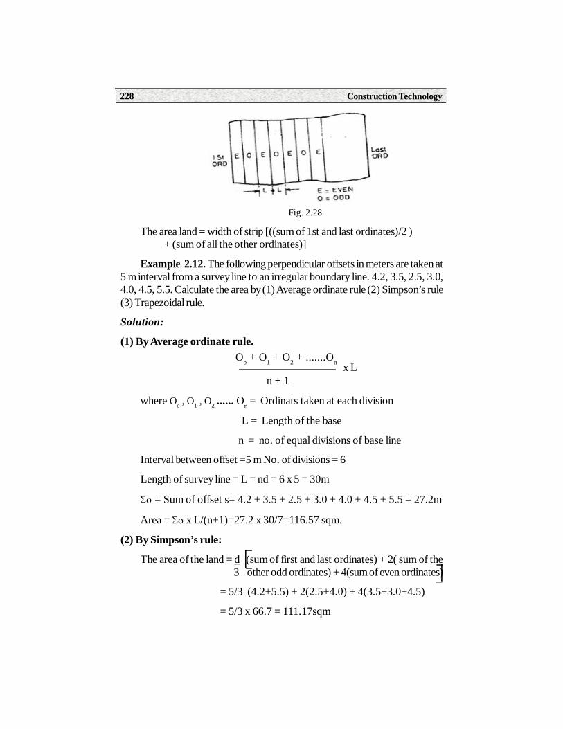
iii) Trapezoidal rule: In this method the area is divided into a number ofequal strips, but any number of strips may be used unlike the Simpson’s rulewhich requires an even number of strips.
Oo + O1 + O2 + .......On x L
Construction Technology228
Fig. 2.28
The area land = width of strip [((sum of 1st and last ordinates)/2 ) + (sum of all the other ordinates)]
Example 2.12. The following perpendicular offsets in meters are taken at5 m interval from a survey line to an irregular boundary line. 4.2, 3.5, 2.5, 3.0,4.0, 4.5, 5.5. Calculate the area by (1) Average ordinate rule (2) Simpson’s rule(3) Trapezoidal rule.
Solution:
(1) By Average ordinate rule.
n + 1
where Oo , O1 , O2 ...... On = Ordinats taken at each division
L = Length of the base
n = no. of equal divisions of base line
Interval between offset =5 m No. of divisions = 6
Length of survey line = L = nd = 6 x 5 = 30m
= Sum of offset s= 4.2 + 3.5 + 2.5 + 3.0 + 4.0 + 4.5 + 5.5 = 27.2m
Area = x L/(n+1)=27.2 x 30/7=116.57 sqm.
(2) By Simpson’s rule:
The area of the land = d (sum of first and last ordinates) + 2( sum of the 3 other odd ordinates) + 4(sum of even ordinates)
= 5/3 (4.2+5.5) + 2(2.5+4.0) + 4(3.5+3.0+4.5)
= 5/3 x 66.7 = 111.17sqm
Oo + O1 + O2 + .......On x L

Paper - II Surveying Theory 229
(3) By trapezoidal rule:
The area of land =
width of strip x [(sum of 1st and last ordinates)) + (sum of all other 2 ordinates)]
Area = 5 (4.2+5.5)/2 + (3.5 + 2.5 + 3.0 + 4.0 + 4.5) =111.75 Sqm.
SUMMARY
1. Accessories used in Chain survey
(i) Chain (ii) Tape (iii) Ranging Rods (iv) offset rod (v) Cross staff (vi) Arrows (vii) Plumb bob (viii) pegs
2. Ranging is the operation of establishing intermediate points on a straight line between two end stations.
3. Types of Ranging
(i) Direct Ranging (ii) Indirect Ranging
4. Base line is the longest line of all the survey lines and which runs across the area.
5. Check line is used to check the accuracy of the frame work as wellas plotting work.
6. Offset is a length measured from a point on a chain line to a detail.
7. Tie line is a line which joins two tie stations.
8. Types of Chains
(i) Metric chain (ii) Engineer’s chain
(iii) Gunter chain (iv) Revenue chain
9. Obstacles in chain surveying
(i) Chaining free but vision obstructed
(ii) Chaining obstructed but vision free
(iii) Both chaining and vision obstructed
10. Methods of calculating Land area
(i) Average ordinate rule (ii) Simpson’s rule (iii) Trapezoidal rule

Construction Technology230
Short Answer Type Questions1. Write the principle of chain surveying
2. Define Baseline
3. Define Ranging and write types of ranging
4. Write types of obstacles in chain surveying
5. What is a check line?
6. What is a tie line?
7. Write the types of survey stations
8. Draw the conventional signs for the following. a) Pond b) Building
9. What is a well conditioned triangle?
10. What is the use of cross staff?
11.A distance of 1200m is measured with 20m metric chain, after themeasurement, it is found that the chain is 10cm long. Correct themeasured distance.
12. Write the methods of calculating areas.
Long Answer Type Questions1. Name and explain the accessories used in chain surveying.
2. Write types of obstacles in chain surveying and explain various methodswhen a survey line is obstructed by a River.
3. Explain the procedure of indirect ranging.
4. Explain the procedure for chaining up a hill slope.
5. Explain the procedure of ranging by line Ranger.
5. The following perpendicular offsets in meters are taken at 5m internalsfrom a survey line to an irregularly boundary line: 4.25, 3.50, 2.95, 2.48, 2.90,3.68, 4.20, 3.85 and 4.15
Calculate the area in sq. meters enclosed between the survey line, the irregularboundary line and the first and last ordinates by i) Average ordinate rule ii)Simpson’s rule and iii) Trapezoidal rule .

Paper - II Surveying Theory 231
Activities• Study the making of metric chains and learn the procedure of unfolding
and folding of chain.
• Range the given two points on the ground.
• Set out a right angle at a given point on the survey line by 3.4.5 method.

Construction Technology232
Learning ObjectivesAfter studying this unit, the student will be able to
• Understand what is meridian and types of meridian
• Bearing and types of bearings
• Representation of bearing
• Conversion of whole circle bearing into quadrantal bearing.
• Calculating included angles of a closed traverse from observedbearings.
• Local attraction, correcting the bearings for local attraction.
3.0 IntroductionAccording to the method employed, surveying is classified into Triangulation
surveying and Traverse surveying. A series of connected survey lines of knownlengths and directions is called a traverse. When triangulation is not possible,traversing method is used. In traversing, when compass is used for making angularmeasurements, it is known as compass traversing or compass surveying.
3.1. PURPOSE AND PRINCIPLES OF COMPASS SURVEYING:
Compass surveying is suitable in the following situations:
1. When the survey work is to be completed quickly.
Compass Surveying
3UNIT
Paper - II Surveying Theory 233
2. When the area is hilly and chaining is difficult.
3. When the area to be surveyed is relatively large.
4. When the details are too many.
5. When the area is can not be divided into network of triangles.
6. When the area to be surveyed is long and narrow e.g. road, streametc.
7. When the survey is to be done through dense forest.
Principle of Compass SurveyingIn compass traversing the directions of survey lines are fixed by angular
measurements and not by forming a network of triangles. A compass surveyis one in which the traverse work consists of series of lines the lengths anddirections of which are measured with a chain or a tape, and with an angularinstrument respectively.
A traverse may be classified as:
a) Closed traverse
b) Open traverse
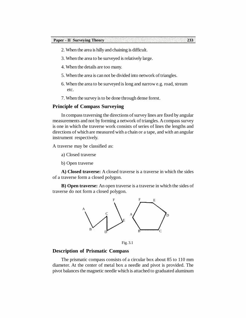
A) Closed traverse: A closed traverse is a traverse in which the sidesof a traverse form a closed polygon.
B) Open traverse: An open traverse is a traverse in which the sides oftraverse do not form a closed polygon.
Fig. 3.1
Description of Prismatic CompassThe prismatic compass consists of a circular box about 85 to 110 mm
diameter. At the center of metal box a needle and pivot is provided. Thepivot balances the magnetic needle which is attached to graduated aluminum
D
E
F
A
B
A
B
C
C
D
EF

Construction Technology234
ring. The graduations are in degrees to 30 minuets and from 00 to 3600 in theclock wise direction. The 00 is marked at south end of magnetic needle becausethe readings are read at the opposite end of the object. At west it is marked 900,north 1800 and east 2700 respectively. The graduations are marked invertedbecause they are viewed through a prism which is cut to 450 on one face and900 for other two faces. The readings get reflected through prism resulting inerected image. A sighting slit is provided in the box carrying the prism. This boxcan be moved up and down for focusing by means of stud. The prism box ishinged so that it can be folded to the rim of the compass box. Two sun glassesare provided to observe bright objects. An object vane is provided in line ofsighting slit. It is an open frame with a central vertical horse hair for sighting theobject. The object vane is hinged to compass. When it is not in use, it is foldedflat on the glass cover. The base of object vane presses the lifting pin bringingthe magnetic needle to rest with the help of lifting lever. A brake pin is providedto stop the oscillations of the graduated ring to facilitate the reading of thegraduated ring. A glass cover is fitted over the box to protect the needlefrom dust. The compass is fitted to a tripod stand. A tripod stand consistsof a ball and socket joint which helps in leveling the compass quickly.
Fig. 3.2

Paper - II Surveying Theory 235
Method of using Prismatic Compass: The compass may be held in thehand, but for better results, it is usually mounted on a tripod which carries avertical spindle in a ball and socket joint to which the box is screwed. By meansof this arrangement the instrument can be quickly leveled and also rotated in ahorizontal plane and clamped in any position.
Working of Prismatic Compass This can be used while holding it in hand, but for better accuracy, it is
usually mounted on a light tripod which carries a vertical spindle in theball and socket arrangement to which compass is screwed. By means ofthis arrangement the compass can be placed in position easily. Its workinginvolves the following steps.
(i) Centering (ii) Levelling, and (iii) observing the bearing
(i) Centering
The compass should be centered over the station where the bearing is tobe taken by dropping a small piece of stone so that it falls on the top of the pegmarking the station.
(ii) Levelling
The compass should then be leveled by eye, by means of a ball and socketjoint so that the ring may swing quite freely. It should be clamped when leveled.
(iii) Observing the bearing.
To observe the bearing of a line AB
1) Centre the compass over the station A and level it.
2) Having turned up vertical prism and the sighting vane, raise orlower the prism until the graduations are clearly visible.
3) Turn the compass box until the ranging rod at the station B is bisectedby the hair when looked through the slit above the prism.
4) When the needle comes to rest, look through the prism and note thereading at which the hair line produced appears to cut the image ofthe graduated ring which gives the required bearing of the line AB.Readings are usually estimated to the nearest 15’.

Construction Technology236
3.2. Concept of Meridian, True Median, Magnetic Meridian and Arbitary Meridian
Meridian: Meridian is a standard direction from which, the bearings ofsurvey lines are measured. There are three types of meridians.
1) True meridian
2) Magnetic meridian
3) Arbitrary meridian.
True meridian: It is a line of intersection of earth’s surface formed by aplane passing through north and south poles and the given place.
Magnetic meridian: It is the direction indicted by a freely suspendedmagnetic needle.
Arbitrary meridian: It is any convenient direction assumed asmeridian for measuring bearings of survey lines.
3.3. Bearing It is a horizontal angle made by the survey line with reference to the
meridian, based on the meridian the bearings are three types.
1) True bearing 2) Magnetic bearing 3) Arbitrary bearing
True bearing: The angle made by a survey line with reference to truemeridian is called true bearing. It is always remains constant.
Magnetic bearing: The angle made by a survey line with reference tomagnetic meridian is called magnetic bearing. It changes from place toplace and time.
Arbitrary bearing: The angle made by a survey line with referenceto arbitrary meridian is called arbitrary bearing.
3.3.1. Representation of BearingBearings are expressed in the following two systems.
1) Whole circle bearings system.
2) Quadrantal bearings system.

Paper - II Surveying Theory 237
1) Whole Circle Bearing
In this system, the bearing of a line is always measured clock wise from thedirection of the north of the meridian towards the line around the circle. Wholecircle bearings of lines have been shown in fig 3.3
Fig. 3.3
2) Quadrantal Bearings
In this system the bearings of a line is measured from either the north or thesouth, clock wise or counter clockwise which ever is nearer to the line towardsthe east or west. The angle at any station in a plane is divided into four quadrantsby two lines at right angles to each other. These are the north south and east-west lines. The bearing is reckoned from 00 to 900 in each quadrant. Quadrantalbearings of lines have been shown in fig 3.4 Quadrantel bearings are also calledas reduced bearings.
Fig. 3.4

Construction Technology238
3.32 Conversion of Whole Circle bearings into Quadrantal Bearings
The whole circle bearing of a line can be converted to quadrantal bearingby reducing it to an angle less than 900 which has the same numerical value ofthe trigonometric functions. Rule of conversion of whole circle bearings intoquadrantel bearing.
Example 3.1
1. Convert the following whole circle bearings of lines to quadrental bearings.
a) OA 320 b) OB 1090 c) OC 2110 d) OD 3030
Solution:
Refer to fig 3.5
Fig. 3.5
S.No. W.C.B QUADRANT RULE
1. Between 0o to 90o N.E Q.B = W.C.B
2. Between 90o to 180o S.E Q.B = 180o-W.C.B
3. Between 180o to 270o S.W Q.B = W.C.B-180o
4. Between 270o to 360o N.W Q.B = 180o-W.C.B
A
B
C
D
320
1090
2110
3030

Paper - II Surveying Theory 239
a) W.C.B of OA = 320
Quadrantal bearing = N 320 E
b) W.C.B of OB = 1090
Quadrantal bearing = 1080 – W.C.B = 1800 – 1090 = S 710 E
c) W.C.B of OC = 2110
Quadrantal bearing = W.C.B – 1800 = 2110 – 1800 = S 310 W
d) W.C.B of OD = 3030
Quadrantal bearing = 3600 – W.C.B = 3600 – 3030 = N 570 W
Example 3.2
Convert following reduced bearings to the whole circle bearings:
(i)N 52o30’E (ii)S 30o 15’E (iii)S 85o45’W (iv)N 15o10’W
Solution:
(i) R.B. = N 52o30’E & which is in the NE quadrant,
Therefore W.C.B =same as R.B = 52o30’ (Ans.)
(ii)S 30o 15’E which is in the SE quadrant,
Therefore W.C.B =180o-30o15’ = 149o45’ (Ans.)
(iii)S 85o45’W which is in the SW quadrant,
Therefore W.C.B =180o+85o45’ = 265o45’ (Ans.)
(iv)N 15o10’W which is in the NW quadrant,
Therefore W.C.B =360o - 15o10’ = 344o50’ (Ans.)
3.4 Compass Traversing in the FieldCompass survey requires the following instruments:
1) Prismatic compass
2) Chain and arrows
3) Tape
4) Ranging rods and

Construction Technology240
5) Pegs.
The compass traversing of an area involves the following steps:
1) Reconnaissance of area
2) Determining the direction of lines
3) Measuring the traverse legs and offsets.
1. Reconnaissance of area: The area is divided into triangles and ofpolygons. Suitable stations are selected on the rough sketch and designatedas A, B, C etc.
2. Determining the directions of survey lines: The compass is set ateach successive stations i.e., A, B, C, D, E of the closed traverse ABCDEAand the fore bearings and back bearings of lines are observed.
3. Measurement of traverse legs and offsets : A compass is centeredover a station A and after leveling the compass the fore bearing AB andback bearing EA are taken by sighting the ranging rods at A and E. The lineAB is chained and the offsets to the detailed points are noted and enteredin the field notes. The operation is repeated at other stations B, C, D, and E
Forward and Backward Bearings
In compass surveying, two bearings are observed for each line, one fromeach end of the line. The bearing of a line in the direction of the progress ofsurvey is called the forward bearing or fore bearing while the bearing measuredin the opposite direction is called as the backward bearing or back bearing.
Fig. 3.6
N1
N2
S
SA
B
B B
F B

Paper - II Surveying Theory 241
The difference between the fore bearing and back bearing of a line is 1800.
Back bearing =fore bearing ± 1800.
Example 3.2: The following are the observed fore bearings of lines of atraverse.
Find their back bearings:
a) AB 420 45’ b) BC 1280 15’
c) CD 2320 15’ d) DE 3010 30’
Solution:
a) FB of AB = 420 45’
BB of AB = 420 45’+1800 = 2220 45’
b) FB of BC = 1280 15’
BB of BC = 1280 15’+1800 = 3080 15’
c) FB of CD = 2320 15’
BB of CD = 2320 15’-1800 = 520 15’
d) FB of DE = 3010 30’
BB of DE = 3010 30’-1800 = 1210 30’
3.5 Local AttractionA compass needle is affected by the presence of masses of iron and steel
such as lamp posts electric cables, steel girders etc., they deflect the needle andthe effect of this disturbance is called local attraction. Due to local attraction, thedifference between the fore bearing and back bearing of a survey line will not beequal to 1800.The observed bearings of lines affected by local attraction arecorrected by starting from the unaffected line and the correct bearings of thesuccessive lines are calculated.
Example 3.3
The following are the bearings of the lines of the closed traverse ABCDAtaken with a compass in a place where local attraction was suspected.

Construction Technology242
Line F.B. B.B.
AB 35030’ 215030’
BC 115015’ 294015’
CD 180045 3045’
DA 283045’ 101045’
Correct the bearings of the lines for local attraction
Solution:
It is observed that the difference between the fore and back bearings of theline AB is exactly 1800, hence stations A and B are free from local attraction andthe bearings observed A and B are correct. The difference of FB and BB ofother lines is not 1800. Local attraction is present at those stations. The observedF.B. of BC is also correct since B is unaffected by local attraction.
Observed F.B. of BC = 115015’
Add = 18000’
Correct BB of BC = 295015’
Less Observed BB of BC = 294015’
Error due to local attraction at C = 1000’
Since the error is negative all bearing observed at C must be corrected byadding 1000’
Observed F.B. of CD = 180o45’
Add correction = 1o 00’
Correct FB of CD = 181045’
Deduct 1800 = 1800 00’
Correct BB of CD = 1045’.
Observed BB of CD = 3045’.
Error due to local attraction at D = 2000’.

Paper - II Surveying Theory 243
Hence all bearings observed at D must be corrected by -2000’ for localattraction.
Observed F.B. of DA = 283045’
Add correction at D = - 2000’
Correct FB of DA = 281045’
Less = 180000’
Correct BB of DA = 101045’
This is the same as the observed BB of DA which shows that there is nolocal attraction at A.
The corrected bearings of the lines will be as follows:
Line F.B. B.B.
AB 35030’ 215030’
BC 115015’ 295015’
CD 181045 1045’
DA 281045’ 101045’
3.6 Calculation of Included Angles of a Traverse in Compass Traverse
When two lines meet at a point two angles i.e., interior and exterior anglesare formed. The sum of these two angles is equal to 3600. The following rulesmay be applied to find the included angle between two lines whose bearings aregiven.
Finding of included angles is divided into two cases as follows:
1. When the W.C.B of two lines measured from their point of intersectionare given
2. When the W.C.B. of two lines not measured from their point ofintersection are given.
Case (1) When the W.C. bearings of two lines measured from their pointof intersection are given

Construction Technology244
Rule: Subtract the smaller bearing from the greater one. The differencewill give the included angle. If it is less than 1800 However if the differenceexceeds 1800 it will be the exterior angle.
The included angle is then 3600 – exterior angle
Example 3.4
Find the angle between the lines OA and OB given their bearings.
i) 25045’ and 140000’ ii) 35015’ and 315015’ iii) 115015’ and 250015’
Solution:
i) OA = 25045’and OB = 140000’
AOB = Bearing of OB – Bearing of OA
= 140000 - 25045’= 114015’
ii) OA = 35015’and OB 315015’
AOB = Bearing of OB - Bearing of OA
= 315015’ - 35015’= 280000’
Since the difference is greater than 1800, it is the exterior angle, Interiorangle
BOA = 360000’ – 280000’ = 80000’
iii) OA = 115015’ and OB = 250015’
AOB = Bearing of OB - Bearing of OA
= 250015’ – 115015’ = 135000’
Example 3.5
The bearing of a line AB is 133030’ and the angle ABC is 120032’what is the bearing of BC?
Solution:
Bearing of AB = 133030’
bearing of BA = 133030’ + 1800 = 313030’
bearing of BC = bearing of BA + Angle ABC
= 313030’ + 120032’ = 434002’
= 434002 - 3600 = 74002’

Paper - II Surveying Theory 245
Example 3.6
The bearings of the sides of a closed traverse ABCDE are as follows:
Side Fore Bearing Back Bearing
AB 105015’ 285015’
BC 2000’ 20000’
CD 229030’ 49030’
DE 187015’ 7015’
EA 122045’ 302045’
Compute the interior angles of the traverse.
A = Bearing of AE Bearing of AB
= B.B. of EA FB of AB
= 302045’ 105015’ 197030’ = exterior angle
Interior angle A = Angle EAB = 3600 – 197030’ = 162030’
B = Bearing of BA Fore Bearing of BC
= B.B. of AB FB of BC
= 285015’ 20000’ = 265015’ = exterior angle
Interior angle B = Angle ABC = 3600 – 265015’ = 94045’
C = Bearing of CB difference Bearing of FB of CD
= B.B. of BC FB of CD
= 20000’ 229030’ = 29030’ = interior angle
D = Bearing of DC FB of DE
= B.B. of CD FB of DE
= 49030’’ 187015’ = 137045’ = interior angle
E = Bearing of ED Fore bearing of EA
Construction Technology246
= B.B. of DE FB of EA
= 7015’’ 122045’ = 115030’
Check: The sum of the interior angles of a closed traverse must equal to(2n-4) right angles, where n is the number of the sides of the traverse. In thiscase the sum of the angles must be equal (10-4) x 900 = 5400.
A + B + C + D + E = 162030’ + 94045’ + 29030’ + 137045’ +115030’ = 5400 00’. Hence checked.
3.7 Errors in Compass SurveyingErrors in compass surveying are classified as follows:
a) Natural Errors b) Instrumental Errors
a) Natural Errors: Natural errors are of two types:
1. Errors of manipulation and sighting
2. Errors due to external influences
1. Errors of manipulation and sighting
i) Inaccurate centering of the compass
ii) Inaccurate leveling of the compass box
iii) Imperfect bisection of the ranging rods at stations
iv) Carelessness in reading the graduations
v) Carelessness in recording the observed readings
2. Errors due to external influences
i) Magnetic changes in atmosphere on a cloudy or stormy day
ii) Variations in declinations
iii) Local attraction due to proximity of steel structures
b) Instrumental Errors:
i) The needle not being perfectly straight
ii) The pivot being bent
iii) The needle being sluggish
iv)The needle not moving freely.

Paper - II Surveying Theory 247
v) The line of sight is not being vertical.
vi) The graduated circle not being horizontal.
vii) The line of sight not passing through the centre of the graduated ringand
viii) The vertical hair being loose.
Summary1. Closed traverse is a traverse in which the sides of a traverse form a
closed polygon.
2. Open traverse is a traverse in which the sides of a traverse do notform a closed polygon.
3. Meridian is a standard direction from which, the bearings of thelines are measured.
4. Types of Meridian.
(i) True meridian. (ii) Magnetic meridian. (iii) Arbitrary meridian.
5. Bearing is a horizontal angle made by the survey line with referenceto the meridian.
6. Bearings of survey lines are represented in
(i) Whole Circle Bearing System. (ii) Quadrantal Bearing System.
7. The difference between fore bearing and back bearing of a lineshould be 1800.
8. Local attraction: A compas needle is affected by the presence ofmasses of iron and steel such as lamp posts, electric cables, steelgirders etc. They deflect the needle and gives the wroing value ofbearing the effect of this disturbanceis called local attraction.
Short Answer Type Questions1. Define bearing
2. Define Meridian
3. Write the methods of representing bearing.
4. Convert the following WCB in to the reduced bearings.
a) 30045’ b) 215015’
Construction Technology248
5. Define local attraction.
6. Write the types of meridian.
7. Find the angles between the lines AB and AC if their respectivebearings are 145030’ and 56045’
8. Define fore bearing and back bearing of a line.
9. What is a closed traverse?
Long Answer Type Questions1. Explain the construction of prismatic compass with a neat sketch
2. Write the errors in compass survey, explain the instrumental errors
3. a) How do you detect local attraction in compass survey?
b) The following bearings were observed with the compass.
Line F.B. B.B.
AB 74015’ 254015’
BC 900 27000’
CD 16500’ 34200’
DE 17800’ 100’
EA 18700’ 800’
Correct the bearings for local attraction
Activities• Study and identify the parts of pismatic compass.
• Measuring magnetic bearing of a line using prismatic compass.

Learning Objectives• Understanding the concept and purpose of levelling.
• Terms like Level surface, datum reduced level, and bench make.
• Temporary adjustments of a dumpy level
• Recording the observations in the field book
• Reduction of levels by H.I. method and Rise and fall methods
• Errors , combined correction for curvative and refraction
4.0 Introduction
Levelling
4UNIT
Levelling is the process of finding the difference in elevation between pointsor relative heights and depths of the objects on the surface of the earth. It is thepart of surveying which deals with the measurements in vertical plane. Levellingis very important to an engineer for the purpose of planning, designing, estimatingand executing various engineering works such as roads, railways, canals, dams,irrigation , pipe lines, buildings and water supply and sanitary schemes .
4.1 Purpose of LevellingLevelling is done for the following purposes.
1. To measure a contour map for fixing sites for reservoirs, dams, etc. andto fix the alignment of roads, railways, irrigation canals and so on.

Construction Technology250
2. To determine the altitudes of different important points on a hill or toknow the reduced levels of different points on or below the surface of the earth.
3. To measure a longitudinal section and cross section of a project (roads,railways, irrigation canals etc) in order to determine the volume of earth work.
4. To prepare a layout map for water supply, sanitary or drainage schemes.
4.1.1 Defination of Terms
Level Surface: a level surface is any surface parallel to the mean spheroidalsurface of the earth, e.g., the surface of a still lake. Each point on the levelsurface is perpendicular to the direction of gravity.
Datum: This is an arbitrary assumed surface with respect to the mean sealevel above which the elevations of points are measured.
Level line: A line lying through out on a level surface is a level line. This isnormal to the plumb line at all points.
Horizontal plane: Horizontal plane through a point is a plane tangential tothe level surface at that point. It is, therefore, perpendicular to the plumb linethrough the point.
Horizontal Line: It is a straight line tangential to the level line at a point. Itis also perpendicular to the plumb line.
Vertical Line: It is a line normal to the level line at a point. It is commonlyconsidered to be the line defined by a plumb line.
Mean sea Level: Mean sea level is the average height of the sea for allstages of the tides. At any particular place it is derived by averaging the hourlytide heights over a long period of 19 years.
Fig. 4.1
Paper - II Surveying Theory 251
Change Point
An intermediate staff station at which both back sight and fore sight aretaken with the purpose of changing the position of the instrument is called achange point or turning point.
Reduced Level
Reduced level is the elevation of the point where the staff reading is takenwith respect to the assumed datum.
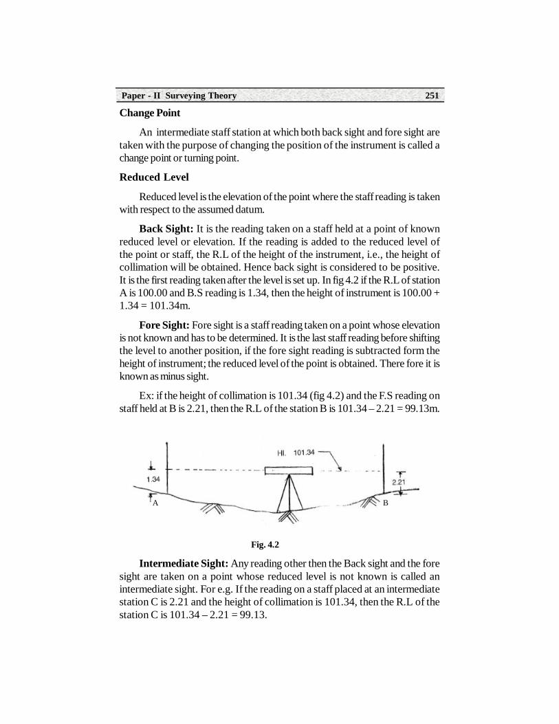
Back Sight: It is the reading taken on a staff held at a point of knownreduced level or elevation. If the reading is added to the reduced level ofthe point or staff, the R.L of the height of the instrument, i.e., the height ofcollimation will be obtained. Hence back sight is considered to be positive.It is the first reading taken after the level is set up. In fig 4.2 if the R.L of stationA is 100.00 and B.S reading is 1.34, then the height of instrument is 100.00 +1.34 = 101.34m.
Fore Sight: Fore sight is a staff reading taken on a point whose elevationis not known and has to be determined. It is the last staff reading before shiftingthe level to another position, if the fore sight reading is subtracted form theheight of instrument; the reduced level of the point is obtained. There fore it isknown as minus sight.
Ex: if the height of collimation is 101.34 (fig 4.2) and the F.S reading onstaff held at B is 2.21, then the R.L of the station B is 101.34 – 2.21 = 99.13m.
Fig. 4.2
Intermediate Sight: Any reading other then the Back sight and the foresight are taken on a point whose reduced level is not known is called anintermediate sight. For e.g. If the reading on a staff placed at an intermediatestation C is 2.21 and the height of collimation is 101.34, then the R.L of thestation C is 101.34 – 2.21 = 99.13.
A B

Construction Technology252
4.1.2. Bench MarkBench mark is a relatively permanent point of reference whose elevation
with respect to some assumed datum is known.
Types of Bench Marks
There are four kinds of bench marks viz.
1. G.T.S bench marks.
2. Permanent bench marks.
3. Arbitrary bench marks and
4. Temporary bench marks.
1. G.T.S Bench Marks
These bench marks are established in the course of the great trigonometricsurvey conducted by the survey of India department with sophisticated instrumentsand under highly accurate and precise conditions of work They are establishedall over the country. Their locations and reduced levels with reference to themean sea level at Karachi are published by the government of India in the formof a catalogue.
2. Permanent Bench Marks
These bench marks are established by state government departments suchas the Irrigation and power, Roads and Buildings, Panchayat raj Engineeringetc. on well defined points such as the parapet wall of a bridge or culvert, cornerof a building, plinth etc. these are connected to G.T.S bench marks and theirlevels are marked on the point.
3. Arbitrary Bench Marks
These are points of reference with any assumed level. These are used onlyfor limited purposes.
4. Temporary Bench Marks
In a continuous program of leveling work it is necessary to close a day’swork on a reference point taken on a permanent location and continue the workthe next day. Such points of reference for leveling are known as Temporarybench marks.
4.2 Types of Levelling InstrumentsThe instruments generally used in levelling are

Paper - II Surveying Theory 253
1. Level 2. Levelling staff.
Level: A level provides a horizontal line of sight from which the heights ofdifferent points are determined. A level consists of the following essential parts.
a) A telescope to provide the line of sight.
b) A level tube to make the line of sight horizontal.
c) A leveling head to bring the bubble to its center of run.
d) A tripod to support the instrument.
4.2.1. Types of Levels
There are chiefly four different types of levels.
a) Dumpy level
b) Wye level
c) Reversible level
d) Tilting level.
Dumpy Level
Fig 4.3 shows the component parts of a Dumpy level
Fig. 4.3

Construction Technology254
Component Parts of Dump Level
1. Tripod Stand: The tripod stand consists of three legs which may besolid or framed. The legs are made of light and hard wood. The lower ends ofthe legs are fitted with steel shoes.
2. Leveling Head: The leveling head consists of two parallel triangularplates having three grooves to support the foot screws.
3. Foot Screws: Three foot screws are provided between the trivetand tribach. By turning the foot screws the tribach can be raised or loweredto bring the bubble to the centre of its run.
4. Telescope: The telescope consists of two metal tubes, one movingwith in the other. It also consists of an object glass and an eye piece onopposite ends. A diaphragm is fixed with the telescope just in front of theeyepiece. The diaphragm carries cross hairs. The telescope is focused bymeans of the focusing screw and may have either external focusing orinternal focusing.
5. Bubble Tubes: Two bubble tubes, one called the longitudinal bubbletube and other the cross bubble tube, are placed at right angles to eachother. These tubes contain spirit bubble. The bubble is brought to the centerof its run with the help of foot screws. The bubble tubes are fixed on tow ofthe telescope.
6. Compass: A compass is provided just below the telescope for takingthe magnetic bearing of a line when required.
4.2.2. Relationship betwen the fundamental lines of a Dumpy levelThe following lines have been identified as the fundamental lines of leveling
instrument.
1. Line of collimation.
2. Axis of bubble tube.
3. Axis of telescope
4. Vertical axis.
Line of collimation: It is an imaginary straight line joining the intersectionof the cross hairs at diaphragm to the optical centre of the object glass and itscontinuation. It is also called the line of sight. When the bubble is in the center ofits run, the line of collimation will be horizontal.
Paper - II Surveying Theory 255
Axis of Bubble tube: It is an imaginary line tangential to the curved surfaceof the bubble tube at its middle point, it is also known as bubble line. When thebubble is in the centre of its run, the bubble line will be horizontal.
Axis of Telescope: It is the imaginary line joining the center of the eyepiece and the optical center of the object glass.
Vertical Axis: The axis about which the telescope can be turned in ahorizontal plane is known as the vertical axis of the instrument.
Relationship between the fundamental lines of dumpy level.
1. Axis of bubble tube should be perpendicular to vertical axis.
2. The line of collimation of telescope is parallel to the axis of bubbletube.
4.3 Types of Levelling StaffsA leveling stave or staff consists of a straight rectangular piece of well
seasoned wood on which graduations are painted. Reading on the staffwith a leveling instrument shows the height of the station above or belowthe line of sight of the level.
Levelling staffs are of two types.
1. Self reading staffs.
2. Target staffs.
In the self reading staff, the level man observes the staff reading wherethe horizontal wire appears to intersect the face of the rod through thelevel. The level man records the readings. The Target staff is provided witha vernier which is adjusted by the staff man under the direction of the levelman who observes through the level, until the horizontal cross hairs of thediaphragm coincides with the center of the vernier. The reading is recordedby the staff man. Target staffs are used where the sights are long. However, these are not commonly used in India.
Self reading staffs are available in 3 forms.
1. Sopwith telescopic staff.
2. Folding metric staff
3. Solid staff.

Construction Technology256
Sopwith Telescopic Staff
The Sopwith telescopic staff is available in 3 parts which telescope intoone another. (Fig 4.4). It is 4 meter long when fully extended. The top length1.25 meters is solid and slides into the bottom box 1.5m long. The extendedlengths are kept in position by means of brass spring catches. The smallestdivision in this staff is 5mm. The meter numbers are marked on the left side andare painted in red. The decimeter numbers are on the right and painted in black.The graduations are marked erect and hence are seen inverted through thetelescope. This is the most commonly used staff in India.
Folding Metric Staff
The folding type staff is lighter, more convenient to handle and gives moreaccurate readings. The folding staff (Fig 4.4) is made of well seasoned wood. Itis 75mm wide, 18mm thick and 4m long. It has two lengths of 2m each andconnected at the middle by means of a locking device. It can be detached intotwo pieces or folded into two or can be attached together to form a rigid andstraight staff. It is fitted with a circular bubble of 25 minutes sensitivity at theback and is provided with two handles. The minimum division on the staff is5mm; each meter length is divided into 200 divisions. The meter numbers arepainted on the right in red. The lines dividing the tenths of meter lengths are alsopainted in red. The tenths of meter numerals are marked on the left and paintedin black and the entire background is painted in white. The graduations areinverted and hence when viewed through the telescope they appear erect.
Solid Staff
It has only one length and is usually 3m long. It is graduated in divisions of5mm in the same way as the telescopic metric staff. It is used for precise levelingwork.
This is much used in America. It is graduated like a Sopwith staff, but isfitted with a sliding vane or target of circular shape. The quadrants are paintedblack and white alternately round a square central hole through which the staffgraduations are visible. The sighting vane is moved up and down until the centerof the target coincides with the horizontal cross hair in the telescope of the level.The rod it self consists of two sliding lengths.
The target staff has the following advantages.
a) It can be used for long sights.
b) It is ideally suits to reciprocal leveling.

Paper - II Surveying Theory 257
c) The surveyor travels with the staff instead of the level. This enables thesurveyor to place the staff at all points on the ground where the slope changes.
Fig. 4.4
4.4 Temporary Adjustments of the LevelTemporary adjustments are those which have to be performed at every
instrument setting and are done before the observations are taken with theinstrument. Permanent adjustments are made when the fixed relationshipbetween the fundamental lines of an instrument is disturbed. Once theseadjustments are made, they last for a long time.
Temporary adjustments of dumpy Level
The temporary adjustments consist of the following two operations.
1. Setting up,
TELESCOPE STAFF

Construction Technology258
2. Leveling up, and
3. Elimination of parallax
1. Setting up
First the instrument is fixed on the tripod, whose legs are then adjusted forapproximate leveling. The instrument is held in one hand and screwed onto thetripod firmly. Next the legs are adjusted to bring the telescope to eye level, andthen further adjusted till the instrument is approximately level, judged by the eyeand the circular spirit- bubble or cross-level tube. In adjusting the tripod, twolegs are kept firmly in a convenient position, and the third is moved sideways in,or out. As required.
2. Leveling up
The telescope is placed parallel to a pair of the foot screws and the longbubble is brought to the center of its run by turning both these foot screws in orout. The telescope is now turned through 90o, kept nearly over the third footscrew, and the bubble brought to the centre again. The process is repeated untilthe bubble remains central for all positions for permanent adjustment.
3. Elimination of parallax: Elimination of parallax involves two steps i)Focusing of the eye piece for distinct vision of the cross hairs at diaphragm andii) focusing theobject glass for bringing the image of the object into the diaphragm.
i). Focusing the eye piece: The telescope is turned towards the sky or apiece of white paper is held in front of the telescope the eye piece is adjustedmoving it in or out till a sharp and distinct image of the cross hairs is seen.
ii). Focusing the object glass: The telescope is directed towards thestaff and the focusing screw is turned until a clear and sharp image of thestaff graduations is obtained. The eye is moved up and down if the readingis not changed, then parallax is completely eliminated, the object glass isfocused every time a staff reading is taken.
4.5 Field Work and Principles of Levelling4.5.1 Simple levelling
The steps involved in the process of simple leveling are:
a) Finding the height of the instrument i.e. R.L of line of sight by taking asight on a known B.M.
b) Finding how much the next point is below or above the line of sight.Suppose it is required to find the elevation of a point B (fig 4.5). Let A be a point

Paper - II Surveying Theory 259
whose elevation is known say 120.12m. The level is setup by approximatelymid way between the points A and B. A staff is held on the point A and the backsight reading is taken say 1.52m. Next turn the telescope to the point B and takethe fore sight on B say 2.66m. Height of instrument = elevation of A + backsight.
= 120.12 + 1.52 = 121.64m.
R.L of B = Height of instrument – foresight. = 121.64 – 2.66 = 118.98m.
Fig. 4.5
4.5.2 Differential LevellingWhen the difference in elevations of points far apart is required, then this
cannot be found in one setting of the instrument. This is determined by differentialleveling. Differential leveling is done by dividing the distance into stages by changepoints on which the staff is held and the difference of levels between successivepair of change points is found. Let A and B be two points very far apart whosedifference in elevation is required (fig 4.6). The distance between the points hasbeen divided into 4 parts by choosing three change points.
Fig. 4.6
120.12
1.52121.64
2.66
118.98
Line of Collimation
101.015102.465 102.130
CP1 CP2 CP3A
B
10.015
0.70
0
2.15
0
2.32
51.
990
1.10
5

Construction Technology260
Let R.L of the point A be 100.00m
The height of the first setting of the instrument is = 100 + 1.015 = 101.015m.
If the fore sight on first change point is 0.700.
The R.L of the C.P.1 = 101.015 – 0.700 = 100.315m.
Similarly R.L of C.P 2 is = 100.315 + 2.150 – 2.325 = 100.140m.
R.L of C.P.3 = 100.140 + 1.990 – 1.105 = 101.025m.
4.5.3 Level BookThe leveling field notes are entered in a note book called the level book.
The pages are ruled with tabulated form to facilitate the booking of readings andreducing levels.
Booking Staff Readings
The following points should be noted while booking readings in a levelbook.
1. The first entry in the level book is a back sight and the last is a foresight.
2. All the readings should be entered in the level book in the respectivecolumns as soon as they are taken.
3. At change points, the fore sight and back sight are recorded in thesame line.
4. The height of instrument should be noted on the same line as backsight.
5. Brief descriptions with sketches of B.M’s, change points, and otherimportant points should be given in the remarks column.
4.5.4 Methods of Booking and Reducing LevelsThere are two methods of booking and reducing the elevations of points
from the observed staff readings.
1. Height of instrument or collimation method.
2. Rise and fall method.
1. Height of Instrument or Collimation Method: In this method, theheight of the instrument and the reduced levels of points are found with referenceto the plane of collimation. The instrument is set up at a convenient point and

Paper - II Surveying Theory 261
back sight is taken on the starting point whose R.L. is known. The height of theinstrument is calculated by adding the back sight to the R.L of the starting point.The R.L of the intermediate points and the first change point are then obtainedby subtracting the respective readings on staff held at these points from theheight of instrument. The instrument is then shifted and set up at the next changepoint. The new height of instrument is found by adding the back sight readingtaken on the change point. The Reduced levels of the successive points and thesuccessive change points are found by subtracting the staff reading from thenew height of instrument. The process is repeated until the R.L of all the pointsis found.
The arithmetical chick as given below is then applied. The difference betweenthe sum of back sights and sum of fore sights should be equal to the differencebetween the last R.L and first R.L.
Thus B.S – F.S = last R.L – First R.L.
The method affords a check for the H.I and R.L of change points but notfor the intermediate points.
The method of booking levels is shown below for the example given below.
Station B.S I.S F.S H.I R.L Remarks
A 1.700 101.700 100.000 B.M
1 2.600 1.800 102.500 99.900 CP1
2 1.135 101.365
3 1.165 101.335
4 2.050 2.165 102.385 100.335 CP2
B 1.810 100.575
TOTAL 6.350 5.775
Fig. 4.7A
B1
2 3
4
1.70
0
1.800
2.60
0 1.13
5
1.16
5
2.16
52.
050
1.81
0

Construction Technology262
Arithmetical check
B.S – F.S = 6.350 – 5.775 = 0.575m
Last R.L – First R.L = 100.575 – 100.000 = 0.575m
Rise and Fall Method
In this method, the R.L’s of points are determined by the difference of levelbetween consecutive points by comparing each point with the point precedingit. The difference between their staff readings indicates a fall or rise according asthe reading is greater on smaller than that of the preceding point. The R.L is thendetermined by adding the rise or subtracting the fall from the preceding point.
Arithmetical Check: There are three checks on the accuracy of thecalculations. The difference between the sum of the back sights and thesum of the fore sights is equal to the difference between the sum of therises and the sum of the falls which is also equal to the difference betweenlast R.L and the first R.L.
B.S – F.S = rise – fall = last R.L – First R.L.
The previous example will now be worked out by the rise and fall method.
Station B.S I.S F.S Rise Fall R.L Remarks
A 1.700 100.000 B.M
1 2.600 1.800 0.100 99.900 C.P.1
2 1.135 1.465 101.365
3 1.165 0.030 101.335
4 2.050 2.165 1.000 100.335 C .P2
B 1.810 0.240 100.575
Total 6.350 5.775 1.705 1.130
Arithmetical check
B.S – F.S = 6.350 – 5.775 = 0.575
Rise – fall = 1.705 – 1.130 = 0.575

Paper - II Surveying Theory 263
Last R.L – First R.L = 100.575 - 100.000 = 0.575
Example 4.1: The following staff readings were taken with a level, theinstrument having been shifted after the 4th, 7th and 10th readings .R.L of thestarting B.M is 100.00 enter the readings in the form of a level book page andreduce the levels by the rise and fall method .Apply usual checks. The readingsare, 2.500, 3.700, 3.850, 3.250, 3.650, 0.370, 0.950, 1.650, 2.850, 3.480,3.680 and 3.270m.
Solution: since the instrument was shifted after the 4th, 7th and 10th
readings, 3.250, 0.950,and 3.480 are the fore sights and the readingsimmediately following them viz. 3.650,1.650 and 3.680are the respectiveback sights. The readings are tabulated and levels are reduced as shownbelow.
B.S = 11.480
F.S = 10.950
RISE = 4.290
FALL = 3.760
LAST R.L = 150.530
FIRST R.L = 150.00
Arithmetical Check
B.S – F.S = 11.480 – 10.950 = 0.530
RISE – FALL = 4.290 – 3.760 = 0.530
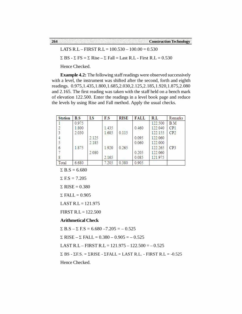
Construction Technology264
LATS R.L – FIRST R.L = 100.530 – 100.00 = 0.530
BS - FS = Rise – Fall = Last R.L - First R.L = 0.530
Hence Checked.
Example 4.2: The following staff readings were observed successivelywith a level, the instrument was shifted after the second, forth and eighthreadings. 0.975,1.435,1.800,1.685,2.030,2.125,2.185,1.920,1.875,2.080and 2.165. The first reading was taken with the staff held on a bench markof elevation 122.500. Enter the readings in a level book page and reducethe levels by using Rise and Fall method. Apply the usual checks.
B.S = 6.680
F.S = 7.205
RISE = 0.380
FALL = 0.905
LAST R.L = 121.975
FIRST R.L = 122.500
Arithmetical Check
B.S – F.S = 6.680 –7.205 = – 0.525
RISE – FALL = 0.380 – 0.905 = – 0.525
LAST R.L – FIRST R.L = 121.975 – 122.500 = – 0.525
BS - F.S. = RISE - FALL = LAST R.L. - FIRST R.L = -0.525
Hence Checked.
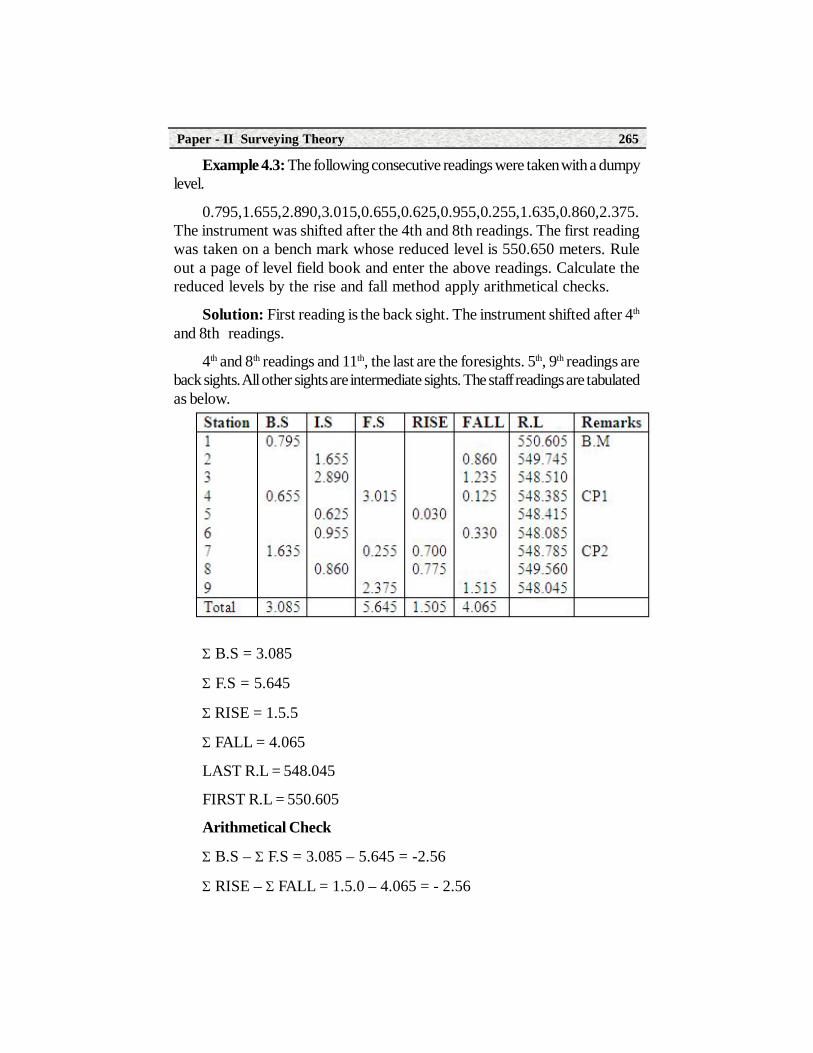
Paper - II Surveying Theory 265
Example 4.3: The following consecutive readings were taken with a dumpylevel.
0.795,1.655,2.890,3.015,0.655,0.625,0.955,0.255,1.635,0.860,2.375.The instrument was shifted after the 4th and 8th readings. The first readingwas taken on a bench mark whose reduced level is 550.650 meters. Ruleout a page of level field book and enter the above readings. Calculate thereduced levels by the rise and fall method apply arithmetical checks.
Solution: First reading is the back sight. The instrument shifted after 4th
and 8th readings.
4th and 8th readings and 11th, the last are the foresights. 5th, 9th readings areback sights. All other sights are intermediate sights. The staff readings are tabulatedas below.
B.S = 3.085
F.S = 5.645
RISE = 1.5.5
FALL = 4.065
LAST R.L = 548.045
FIRST R.L = 550.605
Arithmetical Check
B.S – F.S = 3.085 – 5.645 = -2.56
RISE – FALL = 1.5.0 – 4.065 = - 2.56

Construction Technology266
LAST R.L – FIRST R.L = 548.045 – 550.625 = - 2.56
BS - FS = Rise – Fall = Last R.L - First R.L = -2.56
Hence Checked.
Example 4.4:
The following consecutive readings were taken with a level and 5 meterleveling staff on continuously sloping ground at a common interval of 20 meters,0.890m, 1.535, 2.430, 3.330, 4.235, 5.190, 0.625, 2.005, 3.110, and 4.485.The reduced level of the first point was 108.120. Rule out a page of a level fieldbook and enter above readings .calculate the reduced levels of the points byH.I. method.
Solution
Since the readings were taken on a continuously sloping ground, themaximum staff reading can be F.S and therefore sixth reading will be afore sight taken on a turning point and the seventh reading will be a backsight. Also, the first reading will be a back sight and the last reading will bea fore sight. The levels can be entered as shown in the tabular form.
Station B.S I.S F.S H.I R.L Remarks
1 0.890 108.120 B.M
2 1.535 107.475
3 2.430 106.580
4 3.330 105.680
5 4.235 104.775 C .P1
6 0.625 5.190 104.445 103.820
7 2.005 102.440
8 3.110 101.335
9 4.485 99.960
Total 1.515 9.675
B.S = 1.515
F.S = 9.675
LAST R.L = 99.960

Paper - II Surveying Theory 267
FIRST R.L = 108.120
Arithmetical Check
B.S – F.S = 1.515 – 9.675 = - 8.160
LAST R.L – FIRST R.L = 99.960 – 108.120 = - 8.160
BS - FS = Last R.L - First R.L = -8.160Hence Checked
Example 4.5
The following consecutive readings were taken with a level and 4meter leveling staff on a continuously sloping ground at 30 m intervals0.680, 1.455, 1.855, 2.330, 2.885, 3.380, 1.058, 1.860, 2.245, 3.450, 0.835,0.645, 1.530, 2.250. The R.L of the starting point was 80.750.
a) Rule out a page of level book and enter the above readings.
b) Carry out reductions of heights by Height of Collimation method
c) Apply the arithmetic check.
Check :
B.S = 2.520
F.S = 9.170

Construction Technology268
Horizontal line
Level line
Staff
A
A’B
C
P
First R.L =80.750
Last R.L = 74.100.
B.S- F.S =2.520 -9.170 = -6.650
Last R.L – First R.L =74.100 -80.750 = - 6.650
BS - FS = = Last R.L - First R.L = - 6.650
Hence checked.
4.6 Curvature and RefractionThe surface of the earth is curved. Hence staffs readings will be get affected dueto the curvature of the earth. As the line of sight passes through air of differentdensities, error will be introduced in staff readings due to refraction of light rays.Due to curvature, we get larger staff readings than true readings and hence thepoints sighted appear to be lower than their true positions. Due to the refraction,we get smaller staff readings than true readings. Hence the points sighted appearto be higher than their true positions. Errors due to Curvature and Refractioncorrection should be considered in preciseleveling works involving sights longerthan about 100m.
Error due to Curvature and Correction
In fig. 4.8 given below, let the level be set up at A and let P be the staffstation which is at a horizontal distance of d km. from the instrument. Theline of sight through A which is horizontal cuts the staff held vertically atthe point B and hence the observed staff reading will be PB .But the levelline through A cuts the staff at C and hence PC should be the true staffreading if error is not there due to curvature of the earth.
Fig. 4.8

Paper - II Surveying Theory 269
The error due to curvature in the staff readings is thus the difference of thetwo is CB.
Reffering to the fig given below, let O be the centre of the earth .AC thehorizontal line at the instrument station A, CD the error due to curvature atdistance d km from A. Let R be the radius of the earth. Extend CD to cut thegreat circle through AD at E ,CDE being the vertical at D assuming the sectionof the earth to be circular.
Fig. 4.9
AC2=CD.CE=CD (CD+DE)
AC2=CD.DE neglecting CD2 which is small.
Assuming radius of the earth as 6370 km
CD=Error due to curvature=AC2 / DE=d2/12740
= 0.0000785 d2 km= 0.0785 d2 meters.
Correction for curvature for a distance of d km. = - 0.0785 d2 meters.
Error Due to Refraction and Correction.
The density of air is different at different levels of the earth surface .Hencea ray of light from the staff reaching the instrument under goes refraction. Theerror due to refraction is generally taken as about 1/7 of the error due to thecurvature.
The correction for refraction to the staff reading is positive.
Correction for refraction= +0.0785d2/7 = 0.0112 d2 meters.
Where d is distance of the staff in km.

Construction Technology270
Combined correction due to curvature and refraction
= -0.0785 d2 + 0.0112 d2 = -0.0673 d2.
Summary1. Levelling : Levelling is the process by which the relative heights of
points on the earth’s surface are determined. Levelling deals withmeasurements in a vertical plane.
2. Datum : This is an arbitrary assumed surface with respect to themean sea level above which the elevations of points are measured.
3. Types Of Bench Marks
1. G.T.S bench marks.
2. Permanent bench marks.
3. Arbitrary bench marks and
4. Temporary bench marks.
4. Back Sight : It is the reading taken on a staff held at a point ofknown reduced level or elevation. It is the first staff reading after settingthe level.
5. Fore Sight: Fore sight is a staff reading taken on a point whoseelevation is not known and has to be determined. It is the last staff readingbefore shifting the level to another position.
6. Intermediate Sight: Any staff reading other than the Back sight andthe fore sight are taken on a point where reduced level is not known is called anintermediate sight.
7. Change point : An intermediate staff station at which both back sightand fore sights are taken with the purpose of changing the position of the instrumentis called a change point or turning point.
8. Reduced level: Reduced level is the elevation of the point where thestaff reading is taken with respect to the assumed datum.
9. Line of collimation: It is an imaginary straight line joining the intersectionof the cross hairs at diaphragm to the optical centre of the object glass and itscontinuation. It is also called the line of sight. When the bubble is in the center ofits run, the line of collimation will be horizontal.

Paper - II Surveying Theory 271
10. Curvature : Due to curvature, we get larger staff readings than truereadings and hence the points sighted appear to be lower than their true positions.
11. Rrefraction : Due to the refraction, we get smaller staff readings thantrue readings. Hence the points sighted appear to be higher than their truepositions. Errors due to Curvature and Refraction correction should beconsidered in precise leveling works involving sights longer than about 100m
Short Answer Type Questions1. What is levelling?
2. What is bench mark?
3. What is back sight?
4. Write the methods of reduction of levels?
5. Define curvature?
6. What is profile levelling?
7. What is check levelling?
8. What is change point?
9. What is intermediate sight?
10. Name the types of levels
Long Answer Type Questions1. Draw the neat sketch of dumpy level and name the parts
2. Explain the temporary adjustments of dumpy level
3. Explain differential levelling
4. Write the types of levelling staffs and explain them.
5. Explain the procedure of reducing the levels by H.I method
6. Explain the procedure of reducing the levels by rise and fall method.
7. The following consecutive readings were taken with a level and a4m leveling staff on continuously sloping ground 0.470m BM, 1.500, 2.965,3.980, 0.825, 1.925, 2.950, 3.675, 0.865, 1.950 and 2.990. The R.L of BMwas 150.00 enter the readings in a page of field book. Determine the R.L’s of allthe stations by rise and fall method.

Construction Technology272
8. The following staff readings were taken with a level the instrument hasbeen shifted after the 4th, 7th, and 10th readings, R.L. of the starting BM is100.00. Enter the readings in the form of a level book page and reduce thelevels by H.I., method. Apply usual checks 2.80, 3.60, 3.580, 3.250, 2.370,1,950, 0.650, 1.850, 2.480, 3.860 and 3.720.
Activities• Study the dumpy level and identify the parts.
• Study the levelling staff.
• Make temporary adjustments to the dumpy level and take staffreading at a point.

Learning ObjectivesAfter studying this unit, the student will be able to
• Identify the component parts of Theodolite
• Temporary adjustments of Theodolite
• Measuring horizontal angle between two lines by repetition andreitration methods.
• Measuring vertical angle by Theodolite and determination of height
• Determination of distances of remote objects.
5.0 Introduction
Theodolite Surveying
5UNIT
The theodolite is one of the most versatile and accurate surveying instrumentused for the measurement of horizontal and vertical angles.
Theodolites are primarly classified as (i) Transit (ii) Non – transit
A theodolite is called a transit theodilote, when its telescope can be revolvedthrough a complete revolution about its horizontal axis in a vertical plane, whereas in non – transit type, the telescope can not be transited.
Theodolites are also calssified as (i) Vernier theodolites and(ii) Micrometer theodolites, according as verniers or micrometers are fitted toread the graduated circles. Theodolites are made of various sizes varying from8cm to 25cm the diameter of the graducated circle on the lower plate defining
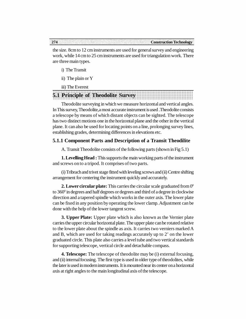
Construction Technology274
the size. 8cm to 12 cm instruments are used for general survey and engineeringwork, while 14 cm to 25 cm instruments are used for triangulation work. Thereare three main types.
i) The Transit
ii) The plain or Y
iii) The Everest
5.1 Principle of Theodolite SurveyTheodolite surveying in which we measure horizontal and vertical angles.
In This survey, Theodolite,a most accurate instrument is used .Theodolite consistsa telescope by means of which distant objects can be sighted. The telescopehas two distinct motions one in the horizontal plane and the other in the verticalplane. It can also be used for locating points on a line, prolonging survey lines,establishing grades, determining differences in elevations etc.
5.1.1 Component Parts and Description of a Transit TheodiliteA. Transit Theodolite consists of the following parts (shown in Fig 5.1)
1. Levelling Head : This supports the main working parts of the instrumentand screws on to a tripod. It comprises of two parts.
(i) Tribrach and trivet stage fitted with leveling screws and (ii) Centre shiftingarrangement for centering the instrument quickly and accurately.
2. Lower circular plate: This carries the circular scale graduated from 00
to 3600 in degrees and half degrees or degrees and third of a degree in clockwisedirection and a tapered spindle which works in the outer axis. The lower platecan be fixed in any position by operating the lower clamp. Adjustment can bedone with the help of the lower tangent screw.
3. Upper Plate: Upper plate which is also known as the Vernier platecarries the upper circular horizontal plate. The upper plate can be rotated relativeto the lower plate about the spindle as axis. It carries two verniers marked Aand B, which are used for taking readings accurately up to 2’ on the lowergraduated circle. This plate also carries a level tube and two vertical standardsfor supporting telescope, vertical circle and detachable compass.
4. Telescope: The telescope of theodolite may be (i) external focusing,and (ii) internal focusing. The first type is used in older type of theodolites, whilethe later is used in modern instruments. It is mounted near its center on a horizontalaxis at right angles to the main longitudinal axis of the telescope.

Paper - II Surveying Theory 275
Fig. 5.1
5. Vertical Circle: The vertical circle is rigidly fixed to the horizontal axisof the telescope and moves with it. It is usually divided into four quadrants. Thegraduations in each quadrant are numbered from 00 to 900 in opposite directionsfrom the two zeros placed at the ends of the horizontal diameter of the verticalcircle so that the line joining the zeros is parallel to the line of collimation of thetelescope when it is horizontal. The sub- divisions on the vertical circle are similarto those of horizontal circle. A clamp and fine motion tangent screws are providedto the vertical circle.

Construction Technology276
6. T-frame or Index Bar: It is T - Shaped and is centered on the horizontalaxis of the telescope in front of the vertical circle. The two verniers C and D areprovided on it at the ends of the horizontal arms called the index arm. A verticalleg, known as clipping arm is provided with a fork and two clipping screws at itslower extremity. The index and clipping arms together are known as T - frame.At the top of this frame a bubble tube is attached which is called the altitudebubble tube.
7. Plumb - Bob: A plumb - bob is suspended from the hook fitted to thebottom of the vertical axis for centering the instrument exactly over a stationpoint.
8. Tripod Stand: The theodolite is supported on a tripod when in use.
5.1.3 Technical Terms1. Centering: It means setting the thedolite exactly over an instrument
station so that its vertical axis immediately above the station mark. It can bedone by means of plumb - bob suspended from a small hook attached to thevertical axis of the theodolite.
2. Transiting : It is also known as plunging or reversing. It is the process ofturning the telescope about its horizontal axis through 1800 in the vertical planethus bringing it upside down and making it point exactly in opposite direction.
3. Swinging the Telescope : It means turning the telescope about itsvertical axis in the horizontal plane. A swing is called right or left according as thetelescope is rotated clockwise or counter clockwise.
4. Face Left : If the vertical circle of the instrument is on the left of theobserver while taking a reading, the position is called the face left and theobservation taken on the horizontal or the vertical circle in this position is knownas the face left observation.
5. Face Right: If the vertical circle of the instrument is on the right of theobserver while taking a reading, the position is called the face right and theobservation taken on the vertical circle in this position is known as the face rightobservation.
6. Changing Face : It is the operation of bringing the vertical circle to theright of the observer, if originally it is to the left, and vice versa. It is done in twosteps. Firstly revolve the telescope through 1800 in a vertical plane and thenrotate it through 1800 in the horizontal plane.
Paper - II Surveying Theory 277
7. Line of Collimation : It is also known as the line of sight. It is theimaginary line joining the intersection of the cross hairs of the diaphragm to theoptical center of the object-glass and its continuation.
8. Axis of the Telescope : The axis of the telescope is the line joining theoptical center of the object glass to the center of the eyepiece.
9. Axis of the level Tube : Axis of the level or bubble tube is the straightline tangential to the longitudinal curve of the level tube at the center of the tube.It is also called the bubble line.
10. Vertical axis : It is the axis about which the telescope can be rotatedin a horizontal plane.
11. Horizontal axis : The horizontal axis is the axis about which thetelescope can be rotated in a vertical plane. It is also called the trunnion axis ortransverse axis.
5.1.4 Temporary Adjustments of TheodoliteThere are three temporary adjustments of a theodolite.
1. Setting up the theodilite over a station
2. Levelling up
3. Focussing for elimination of parallex
Setting Up : It includes two operations, viz (a) Centering the theodoliteover a station and (b) approximately leveling it by tripod legs only. Centering ofa theodolite over a station can be done by means of a plumb bob suspendedfrom the hook beneath the center of the instrument.To do this
(i) Place the instrument over the station by spreading the legs of the tripodwell apart, keeping the telescope at a convenient height, the plumb bobapproximately over the station mark. (ii) Lift the instrument bodily withoutdisturbing the relative positions of the legs and move it until the plumb bob hangsabout 2 cm above and within about 1 cm or less horizontally of the stationmark.(iii) Move each leg radially as well as circumferentially so as to bring theplumb bob exactly over the station mark. Press the legs firmly into the ground.
Levelling up : Having centered and approximately levelled, the instrumentshould be levelled accurately with reference to the plate levels by means of foot- screws so that the vertical axis is made truly vertical. To level the instrument.(a)Loosen all clamps and turn the instrument about either of its axis until the longerplate level is parallel to any pair of foot - screws, the other plate level will then

Construction Technology278
be parallel to the line joining the third foot - screw and the mid - point of the linejoining the first pair. (b) Bring the long bubble to the center of its run byturning both screws equally, either inward or both outwards.
(c ) Repeat this until both the bubbles are exactly centered. Now rotate theinstrument about the vertical axis through a complete revolution. Each bubblewill now remain central provided the plate levels are in correct adjustment. Thevertical axis is thus made truly vertical.If the vertical angles are to be measured,the instrument should be leveled with reference to the altitude level fixed on theindex arm. To do this (a) First level the instrument by plate levels. Then turn thetelescope so that the altitude level is parallel to the line joining a pair of foot -screws and bring the bubble to the center of its run by means of these screws.(b) Turn the telescope through 900 in the horizontal plane and make the bubblecentral by the third foot screw. (c) Repeat this until the bubble remains central inthese two positions. (d) Bring the altitude level over the third foot – screw andswing the telescope through 1800. If now the bubble does not remain central,correct half its deviation by clip screw and the other half by the third foot -screw swing the telescope through 900 so that it is again parallel to the two footscrews and then make the bubble central by means of these screws.
Focusing: Focusing is done in two steps
(a) Focusing of the eye - piece for distant vision of the cross - hairs atdiaphragm, and
(b) Focusing the object glass for bringing the image of the object into theplane of the diaphragm.
(a) Focusing the Eye - Piece: Point the telescope to the sky or hold apiece of white paper in front of the telescope. Move the eye - piece in and outuntil a distant and sharp black image of the cross - hairs is seen.
(b) Focusing the Object -Glass: Direct the telescope towards the objectand turn the focusing screw until a clear and sharp image of the object is obtained.It may be noted that parallax is completely eliminated if there is no movement ofthe image of the object when the eye is moved up and down.
Reading the Circular Vernier Scales
Circular vernier scales are used in thedolites to measure horizontal andvertical angles. Fig. 5.2(a) and 5.2 (b) shows two typical arrangements of doubledirect ciruclar verniers. In Fig. 5.1(a) the main scale is gruaduated to 30’ (s=30’)and the number of divisions n=30 on the vernier.
Hence the least count is s/n=30’/30 = 1’ .

Paper - II Surveying Theory 279
In Fig. 5.1(b), the main scale is graduated to 20’ (s=20’) and the number ofvernier divisions n=40.
Hence least count= s/n = 20’ / 40 = 0.5’ = 30”
Fig. 5.2
Thus in fig. 5.2 (a) the clock wise angle reading (inner row) is342o 30’ + 05’ = 342o 35’, and the counter clock wise angle reading (outerrow) is 17o 0’ + 26’ = 17o 26’. Similarly in fig. 5.2(b) clockwise angle reading(inner row) is 49o 40’ + 10’ 30’’ = 49o 50’ 30’’ and the counter clock wise angle(outer row) is 130o 0’ + 9’ 30’’ = 130o 9’ 30’’.
In both the cases, the verneir is always read in the same direction as thescale.
Now a days theodolites are available with least count of 20’’.
5.2 Measurement of Horizontal AnglesThere are three methods of measuring horizontal angles.
1. Ordinary method
2. Repitation method
3. Reiteration method

Construction Technology280
1. Ordinary Method : to measure horizontal angle AOB show in fig. 5.3
(i) Setup the instrument over ‘0’ and level it accurately.
(ii) Set the vernier ‘A’ to the zero or 360o of the horizontal circle. To do thisloosen the upper clamp and turn the upper plate until the zero of verner A nearlycoincides with the zero of the horizontal circle. Tighten the upper clamp and turnits tangent screw to bring the two zeros into exact coincidence.
(iii) Loosen the lower clamp, turn the instrument and direct the telescopeapproximately to the left hand object (A) by sighting over the top of the telescope.Tighten the lower clamp and bisect, exactly by turning the lower tangent screw.Bring the point A into exact coindence with the point of intersection of crosshairs at diapharm by using the verticle circle clamp and tangent screws.Alternatively bring the vertical cross hairs exactly on the lowest visible portionof the arrow or the ranging rod representing the point A in order to minimise theerror due to non verticality of the object.
(iv) Having sighted the object A, see whether the vernier A still reads zero.Read the vernier B and record both vernier readings.
(v) Loosen the upper clamp and turn the telescope clockwise until the lineof the sight is set nearly on the right hand object (B). Then tighten the upperclamp and by turning its tangent screw, bisect B exactly.
(vi) Read both Verniers : The readings of the vernier A which was initiallyset at zero gives the values of angle AOB directly and that of the other vernier Bby deducting 180o. The mean of two vernier readings gives the value of therequired angle AOB.
Fig.5.3
A B
O

Paper - II Surveying Theory 281
(vii) Change the face of the instrumnet and repeat the whole process. Themean of the two vernier readings gives the second value of the angle.
(viii) The mean of the two values of the angle AOB, one with the face leftand the other with the face right, gives the required angle free from all instrumentalerrors.
2. Measurement of Horizontal angle by Repetition Method: In thismethod, the angle is added several times mechanically, and the value of theangle obtained by dividing the accumulated reading by the number of repetitions.
To measure the angle PQR
(i) Set the instrument at Q and level it. With the help of upper clamp andtangent screw, set 0o reading on vernier A. Note the reading of vernier B.
(2) Loose the lower clamp and direct the telescope towards the point P.clamp the lower clamp and bisect point P accurately by lower tangent screw.
(3) Unclamp the upper clamp and turn the instrument clockwise about theinner axis towards R. Clamp the upper clamp and bisect R accurately with theupper tangent screw. Note the reading of verniers A and B to get the approximatevalue of the angle PQR.
(4) Unclamp the lower clamp and turn the telescope clockwise to sight Pagain. Bisect P accurately by using the lower tangent screw. It should be notedthat the vernier readings will not be changed in this operation since the upperplate is clamped to the lower.
(5) Unclamp the upper clamp, turn the telescope clockwise and sight R.Bisect R accurately by upper tangent screw.
(6) Repeat the process until the angle is repeated the required number oftimes (usually 3). The average angle with face left will be equal to final redingdivided by three.
(7) Change face and make three more repetitions as described above.Find the average angle with face right, by dividing the final reading by three.
(8) The average horizontal angle is then obtained by taking the average ofthe two angles obtained with face left and face right.
Any number of repetitions may be made. How ever, three repetitions withthe telescope normal and three with the telescope inverted are quite sufficientfor any thing except very precise work. Table 5.4 gives the method of recordingobservations by method of repetition.
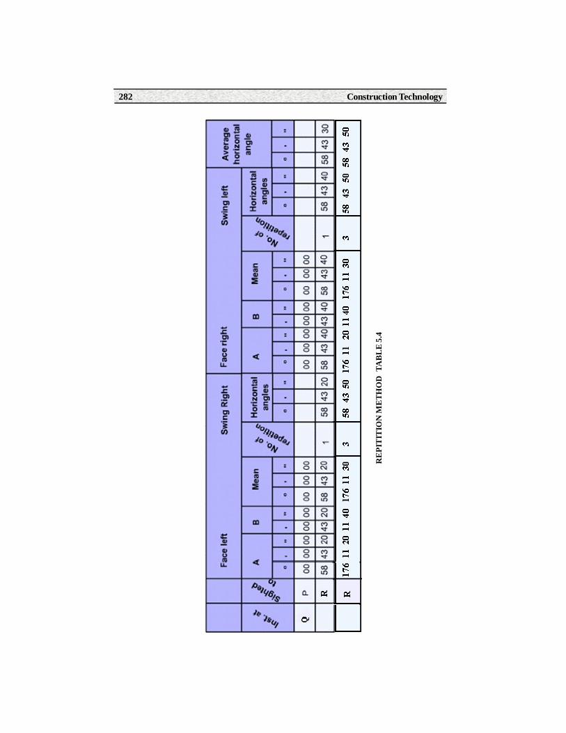
Construction Technology282
RE
PIT
ITIO
N M
ETH
OD
TA
BL
E 5
.4

Paper - II Surveying Theory 283
By this procedure the following errors are eliminated or minimized.
(i) The errors due to the eccentricity of the centers and of the verniers areeliminated by reading both verniers and averaging the readings.
(ii) The errors due to imperfect adjustment of the line of collimation and thehorizontal axis of the telescope are eliminated by face left and face rightobservations.
(iii) The errors of graduations are minimized.
2. Measurement of Horizontal Angle by Reiteration Method
Reiteration is another method of measuring horizontal angles with highprecision. It is less tedious. It is generally preferred when several angles aremeasured at a particular station. In this method several angles are measuredsuccessively, and finally the horizon is closed. The final reading of the leadingverneir (Vernier A) should be the same as its initial reading. If not, the discrepancyis equally distributed among all the measured angles.
Fig. 5.4
Suppose it is required to measure the angles POQ, QOR and ROS
(i) Set up the instrument over O and level it correctly.
(ii) Setup the Verneir A to Zero
(iii) Direct the telescope to some well – defined object P or the stationpoint A, which is known as the Referring object and bisect it accurately by usingthe lower clamp and lower tangent screw. Note the Vernier readings.
(iv)Loosen the Upper plate and turn the telescope clockwise until the pointQ is exactly bisected by turning the upper tangent screw. Read both Verniers.The mean of two vernier readings will give the value of the angle POQ.
P
Q
RS
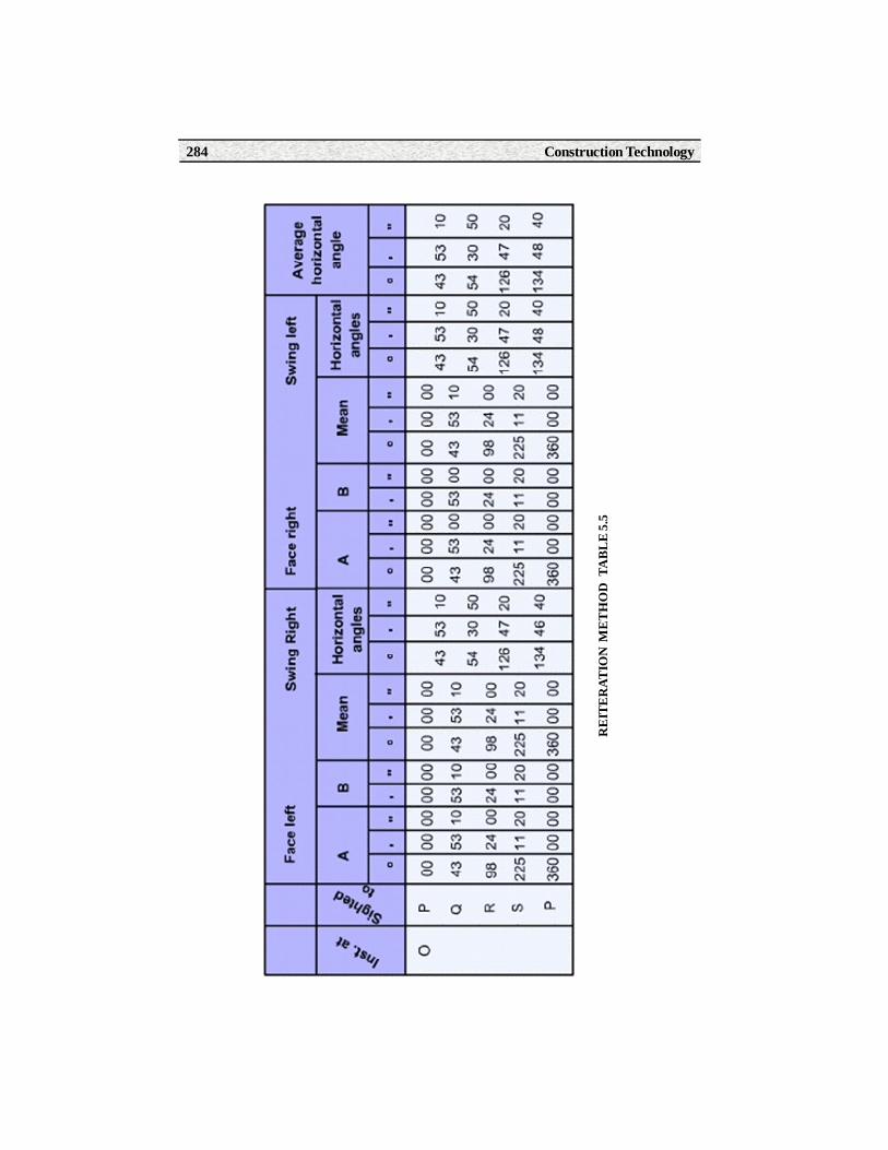
Construction Technology284
RE
ITE
RAT
ION
ME
TH
OD
TA
BL
E 5.
5

Paper - II Surveying Theory 285
(v) Similarly, bisect R and S successively, reading both verniers at eachbisection
(vi) Finally close the horizon by sighting the referring object (p) or the stationpoint P.
(vii) The Vernier A should now read 3600. If not, note the reading and findthe error.
(viii) If the error is small, it is equally distributed among the several observedangles. If large, the readings should be discarded and a new set taken.
5.2.1. Measuring a Vertical AngleA Vertical angle is an angle between the inclined line of sight and the
horizontal. It may be an angle of elevation or depression according as the objectis above or below the horizontal plane.
To measure the vertical angle of an object A at a station O
(i) Set up the theodolite at a station O and level it accurately with referenceto the altitude bubble.
(ii) Set the zero of vertical verneir exactly to the zero of the vertical circleby using the vertical circle clamp and tangent screw.
(iii) Bring the bubble of the altitude level in the central position by using theclip screw. The line of sight is made horizontal, while the vernier reads zero.
(iv) Loosen the vertical circle clamp screw and direct the telescope towardsthe object A and sight it exactly by using vertical circle tangent screw.
(v) Read both verniers on the vertical scale. The mean of the two vernierreadings gives the value of the required angle.
(vi) Change the face of the instrument and repeat the process. The mean ofthe two vernier readings gives the second value of the required angle.
(vii) The average of the two values of the angle thus obtained is the requiredvalue of the angle free from instrumental errors.
To measure the vertical angle between two points A and B
(i) Sight A as before, and take the mean of the two vernier readings at thevertical circle let it be .
(ii) Similarly sight B and take the mean of the two Vernier readings at thevertical circle. Let it be .

Construction Technology286
VER
TIC
AL
AN
GLE
S T
ABL
E 5.
6

Paper - II Surveying Theory 287
(iii) The sum or difference of these readings will give the value of the verticalangle between A and B according as one of the points is above and the otherbelow the horizontal plane (Fig a) or both points are on the same side of thehorizontal plane (Fig b and c)
The observations of vertical angles are shown in table 5.5
Fig. 5.5
5.3 Determination of Heights and DistancesWhen the base of the object being accessible:
To find the height of the object above a Bench Mark (or above the instrumentstation)
Fig. 5.6
horizontal line
A
B
O
A
B
B
O
B
O
Fig. aFig. b
h
hs
BM
D

Construction Technology288
Let H = the height of the object above the B.M
hs = height of the instruments axis above the B.M
h = height of the object above the instrument axis
= the vertical angle observed at the instrument station
D = the horizontal distance in meters measured from the instrument stationto the base of the object.
Then h = D Tan
H = h + hs
H = D Tan + hs
When the distance D is large, the correction for curvature and
refraction {0.0673 (D/1000)2 } shall have to be applied.
Example : A Theodolite was setup at a distance of 175 m from a chimney,and the angle of elevation to its top was 10030’. The staff reading on a B.M ofR.L 70.50 with the telescope horizontal was 0.982. Find the height of the chimneyabove the B.M.
D = 175 m, = 10030’
hs = 0.982
The height of the top of the chimney above the instrument
axis h = D Tan
= 175 x Tan 100301.
= 175 X 0.1853
= 32.43 m
The error due to curvature & refraction
= 0.0673 (175/ 1000)2 = 0.002 m
The height of the top of the chimney above the B.M=
H= h + hs + correction due to curvature and refraction
H = 32.43 + 0.982 + 0.002
= 33.414 m. Ans.

Paper - II Surveying Theory 289
Summary1. Types of levels
i) The Transit ii) The plain or Y iii) The Everest
2. Face Left : If the vertical circle of the instrument is on the left of theobserver while taking a reading, the position is called the face left and theobservation taken on the horizontal or the vertical circle in this position is knownsas the face left observation.
3. Face Right : If the vertical circle of the instrument is on the right of theobserver while taking a reading, the position is called the face right and theobservation taken on the vertical circle in this position is known as the face rightobservation.
4. Temporary Adjustments of Theodolite
1. Setting up the theodilite over a station 2. Levelling up 3. Focussing
5. Repetition: In this method, the angle is added several times mechanically,and the value of the angle obtained by dividing the accumulated reading by thenumber of repetitions.
Short Answer Type Questions1. State any four uses of a theodolite
2. What is meant by Centering ?
3. What is meant by Transiting ?
4. What is meant by swinging the telescope?
5. What is meant by face left?
6. What is meant by face right?
7. What is meant by changing the face?
8. Define the line of collimation
9. Write methods of measuring horizontal angle
10. Write the temporary adjustments of Theodolite.
11. Define vertical axis
12. What are the Fundamental lines of a Transit Theodolite?

Construction Technology290
Long Answer Type Questions13. Describe the parts of a Theodilite with transiting facility for use in
measurement in a horizontal plane.
14. Draw a neat sketch of transit Theodolite and mention itscomponents.
15. Explain clearly and sequentially the operations involved in thetemporary adjustments of a Theodolite.
16. Explain how you would measure with a Thodolite.
(a) Horizontal angle by repetition
(b) Horizontal angle by reiteration
Activities• Study the Theodolite and identifying the parts.
• Making temporary adjustments to the Theodolite
• Reading the Verniers and recording the observation in the field book.
Learning ObjectivesAfter studying this unit, the student will be able to
• Understand the parts of Total station
• Temporary adjustments of total station
• Measurement of horizontal angle, horizontal distance by total station
• Measurement of diffference in elevation between two points
• Setting out plan of a building on the ground
• Measuring area of a closed traverse
• Working of Distomat
6.1 Introduction
Total Station & Distomat
6UNIT
A Total station is a combination of an electronic theodolite and anelectronic distance meter (EDM).This combination makes it possible todetermine the coordinates of a reflector by aligning the instruments cross-hairs on the reflector and simultaneously measuring the horizontal andvertical angles and slope distances. A Total station records, reads andperforms necessary computations with the help of micro-processor in theinstrument. Total stations also generate maps by transferring data to acomputer.

Construction Technology292
Parts of a Total station. Following are the parts of a total station.
1. Latch button. 2. On board battery 3. Telescope tangent screw4. Telescopic Clamp screw 5. Plate Vial. 5. Power Supply Switch 6. Clampscrew 7. Tangent screw 8. Tribrach locking lever 9. Levelling screw10. Bottom plate 11. Focusing knob 12. Eyepiece lens 13. Plate vial14. Display panel 15. Keyboard 16. Date out connector 17. External bateryconnector 18. Circular vial.
Fig.6.1

Paper - II Surveying Theory 293
Functions of Total Stations
Total station performs the following functions.
1. Averaging multiple angles and distance measurements.
2. Correcting electronically measured distances for prism constants,atmospheric pressure and temperature.
3. Making curvature and refraction corrections to elevations determinedby trigonometric leveling,
4. Reducing slope distances to their horizontal and vertical components.
5. Calculating elevations of points from the vertical distancecomponents.
Adjustments of Total station for taking observations.
For most surveys, prior to observing distances and angles the instrumentmust first be carefully set up over a specific point.
The set up process is mostly accomplished with the following steps:
1) Adjust the position of the tripod legs by lifting and moving thetripod as a whole until the point is roughly centered beneath the tripodhead (by dropping a stone or using a plumb bob).
2) Firmly place the legs of the tripod in the ground.
3) Roughly center the tribrach leveling screws on their posts.
4) Mount the tribrach approximately in the middle of the tripod headto permit maximum translations in step (9) in any directions.
5) Properly focus the optical plummet on the point,
6) Manipulate the leveling screws to aim the intersection of cross hairsof the optical plummet telescope at the point below,
7) Center the bull’s eye bubble by adjusting the lengths of the tripodextension legs,
8) Level the instrument using the plate bubble and leveling screws
9) If necessary, loosen the tribrach screw and translate the instrument(do not rotate it) to carefully center the plummet cross hair on the point.
10) Repeat step (8) and (9) until precise leveling and centering areaccomplished.

Construction Technology294
To level a total station instrument, the telescope is rotated to place the axisof the level vial parallel to the line through any two leveling screws, as the linethrough A and B in Figure(a).
The bubble is centered by turning these two screws, then rotated 90°, asshown Figure(b), and centered again using the third screw (C) only.
The process is repeated and carefully checked to ensure that the bubbleremains centered .
Fig.6.2
6.2 Measurement of Horizontal Distance, Slope distance and difference in height between two points
Total station measures only three parameters: These are Horizontal angle,vertical angle, and Slope distance. It does basic calculations and displays otherparameters such as horizontal distance, coordinates of a point, area of a closedtraverse etc.
Fig. 6.3
A B
C
A B
C
Direction of screwrotation left thumb
Bubble direction
Bub
ble
dire
ctio
n
Direction ofrotation
(a) (b)
Tota
l Sta
tion
Line of sight
Ref
lect
or
HR
BV=S Cos Z
H = S Sin Z
S
HI
A
Z
Paper - II Surveying Theory 295
S=slope distance, V = vertical distance between telescope and reflectorH = Horizontal distance Z = Zenith angle HI= Instrument height, HR = Reflectorheight
Slope distance: Total station to reflector distance is measured using anElectronic Distance Meter (EDM).EDM emits an infrared light beam. The emittedbeam reflected by the reflector and received and amplified by the total station.The received signal is then compared with a reference signal generated by theinstrument and the phase-shift is determined. This phase-shift is a measure ofthe travel time and thus the distance between the total station and reflector.
Horizontal distance: From fig.6.3 the Horizontal distance from theinstrument to the reflector (H) is given by
H = S cos (90o - Z) = S Sin Z where S is the slope distance
And Z is Zenith angle.
Difference in heights between two points: From the fig.6.3
HI = height of the instrument
HR = height of the reflector.
V = vertical distance between telescope and reflector.
difference in heights between two points A and B on the ground
d = V+ (HI – HR)
V= S Sin (90o-Z) = Scos Z substituting V value in above equation.
d = S cos Z + (HI – HR)
6.3 Elevation of a PointFrom fig.6.3 the elevation of point B is given by
Elevation of point B = elevation of point A + HI +V – HR where
HI = height of the instrument.
HR = height of the reflector.
V = vertical distance between telescope and reflector.
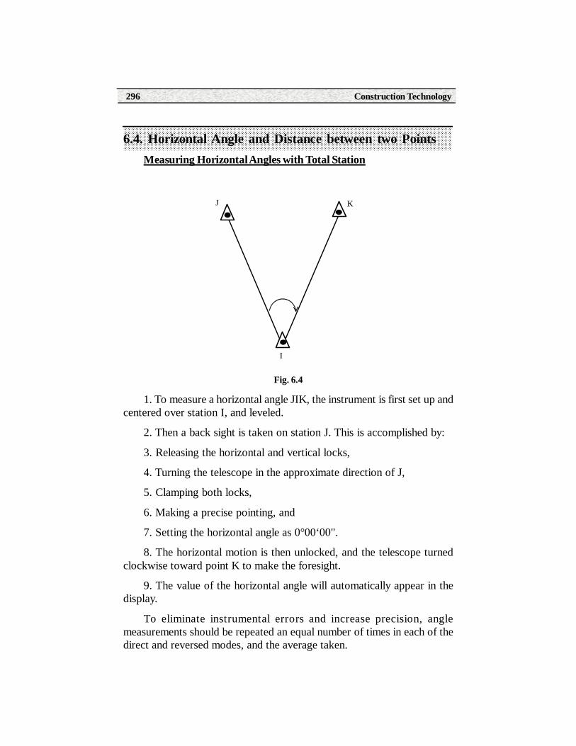
Construction Technology296
6.4. Horizontal Angle and Distance between two PointsMeasuring Horizontal Angles with Total Station
Fig. 6.4
1. To measure a horizontal angle JIK, the instrument is first set up andcentered over station I, and leveled.
2. Then a back sight is taken on station J. This is accomplished by:
3. Releasing the horizontal and vertical locks,
4. Turning the telescope in the approximate direction of J,
5. Clamping both locks,
6. Making a precise pointing, and
7. Setting the horizontal angle as 0°00‘00".
8. The horizontal motion is then unlocked, and the telescope turnedclockwise toward point K to make the foresight.
9. The value of the horizontal angle will automatically appear in thedisplay.
To eliminate instrumental errors and increase precision, anglemeasurements should be repeated an equal number of times in each of thedirect and reversed modes, and the average taken.
I
J K

Paper - II Surveying Theory 297
Distance between two points.
The distance between two points can be horizontal, slope, or vertical. Atape measure or an EDM device (such as a total station) can measure horizontaland slope distances. A distance measured on a slope can be trigonometricallyconverted to its horizontal equivalent by using the slope angle or vertical differenceof elevation and the procedure is explained in article 6.2.
6.5 Setting Out Right angles at different points on a base line
The most accurate way to set out a right-angle is to use a theodolite or atotal station. Position the instrument on the point along the survey line fromwhich the right-angle is to be set out, target the end point of the survey line, setthe horizontal circle to zero and turn the total station until the horizontal circlereading is 90o
.
6.6 Setting out Plan of a Building on the Ground
Fig 6.5
During building alignment, it is useful to extrapolate the sides of the buildingto beyond the limits of the excavation and there to erect profile boards on whichthe extensions are marked exactly by hammering in nails. These can be connectedto strings or wires at any time during the construction sequence, indicating therequired positions of the walls. In the following example, profile boards are tobe erected parallel to the proposed walls of a large building and at distances ofa and b respectively from the boundaries (fig. 6.5).

Construction Technology298
1. Establish a baseline AB parallel to the left-hand boundary and at a freelyselectable distance c.
2. Mark the point A at the defined distance d from the upper boundary; itwill be the first location for the total station.
3. Using a boning rod, mark the point B at the end of the baseline.
4. Set up the total station on point A, target point B, and set out the pointsA1, A2 and A3 in this alignment in accordance with the planned length of theside of the building.
5. With point B sighted, set the horizontal circle to zero, turn the total stationby 90° and set out the second line AC with the points A4, A5 and A6.
6. The points on the profile boards are then set out in a similar manner,starting from the points A1 to A6 respectively.
If the foundations have not yet been excavated, you can set out thesides H1H2 and H1H3 of the building directly and use them as the startingline for marking the points on the profile boards.
For smaller buildings it is easier to set out the profile boards using anoptical square (right-angle prism) and a measuring tape. A building-alignment software program incorporated into many total stations enablesprofile boards to be set out directly, starting with any instrument station.
6.7 Prolonging a Straight LineBy using a Total station, a straight line can be prolonged by double centre
method.
The procedure is as follows.
1. Set up the instrument on the line to be prolonged.
2. Select a point A on the line.
3. Take Back sight on point A with telescope direct. Plunge and set a point C’.
4. Take Back sight on point A with telescope reverse. Plunge and set a point C”.
5. Mark C at the mid point between C’ and C”.

Paper - II Surveying Theory 299
6.8 Area of a Closed Traverse
Fig 6.6
1. Set up the Total station in the terrain so that it is within view of the entirearea to be surveyed. It is not necessary to position the horizontal circle.
2. Determine the boundary points of the area sequentially in the clockwisedirection. You must always measure a distance.
3. Afterwards, the area is calculated automatically at the touch of a buttonand is displayed.
6.9 Earth Work CalculationTo calculate the required earth work, information is needed about both the
current graded surface and proposed graded surface. These can be calculatedby using contour data in the form of maps or coordinate data of points fromTotal station data. Soft wares like Auto CAD civil 3D, E Survey CAD are usedfor calculation of earth work.
6.10 DistomatsDistomats are latest in the series of EDM instruments. These instruments
measure distances by using amplitude modulated infrared waves. Two identicalinstruments are used, one at each end of line to be measured. The master unitsends the signals to the remote unit, which receives and reflects back the signals.The instrument can automatically send each of the signals and calculates thephase-shift in each case. The distance is then automatically displayed.
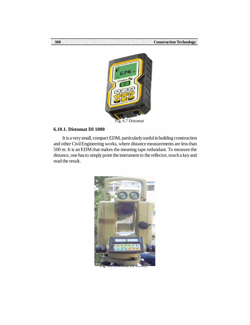
Construction Technology300
Fig. 6.7 Distomat
6.10.1. Distomat DI 1000
It is a very small, compact EDM, particularly useful in building constructionand other Civil Engineering works, where distance measurements are less than500 m. It is an EDM that makes the meaning tape redundant. To measure thedistance, one has to simply point the instrument to the reflector, touch a key andread the result.
Fig. 6.8 Distomat DI 1OOO.

Paper - II Surveying Theory 301
Summary1. A Total station is a combination of an electronic theodolite and an electronic
distance meter (EDM).
2. Fundamental measurements of a total station are Horizontal angle,Vertical angle and slope distance.
3. Objectives of Total station are
i). Meauring horizontal and vertical angles.
ii). Measuring Horizontal distance.
iii) Measuring difference in elevation between two points.
iv). Determining elevation of a point.
v).Setting out right angles.
vi). Prolonging a straight line.
vii). Measuring area of a closed traverse.
4. Distomats are latest in the series of EDM instruments. Theseinstruments measure distances by using amplitude modulated infraredwaves.
Short Answer Type Questions1. What is Total station?
2. Write functions of Total station.
3. Write the adjustments required for total station for takingobservations.
4. What are the fundamental measurements of total station?
5. Write the objectives of total station.
6. What is a Distomat?
Long Answer Type Questions1. Explain measurement of distance by total station.
2. Explain measurement of horizontal angle by total station.

Construction Technology302
3. Explain the procedure of setting out a building on the ground usinga Total station.
4. Explain the procedure of measuring area of a closed Traverse usingTotal station.
5. Explain adjustments of Total station before taking observations.
Activities• Identify the parts of Total station.
• Make temporory adjustments to the Total station

Paper - II Surveying Theory 303
MODEL PAPER
SUB : SURVEYING
I YEAR (C.T., W.S & S.E)
Time: 3 hrs Max marks : 50
SECTION – A
Note: 1) Attempt all questions
2) Each question carries 2 marks
1. Define Surveying.
2. What is Ranging?
3. Write types of obstacles in chain surveying.
4. Define Bearing.
5. What is Base line?
6. Define Bench mark.
7.What is curvature correction?
8. What is Back sight?
9. What is a Total station?
10. Write any two objectives of Total station.
SECTION – B
Note: 1) Attempt any five of the following
2) Each question carries 6 marks
11. Explain the accessories used in chain surveying with neat sketches.
12. Explain the method of indirect ranging.
13. Explain the procedure of chaining along sloped ground.
14. The following are the observed bearings of the lines of a traverse A BC D taken with a compass in a place where local attraction was suspected.Correct the bearings for local attraction and calculate the included angles of thetraverse.
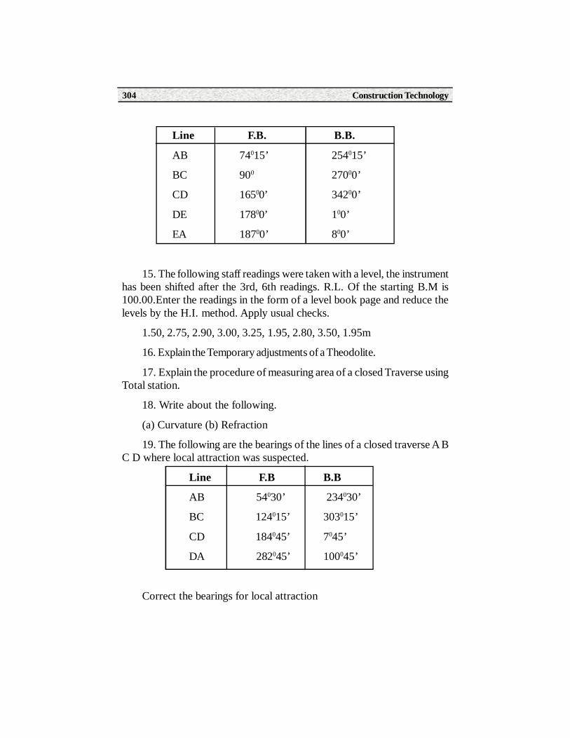
Construction Technology304
Line F.B. B.B.
AB 74015’ 254015’
BC 900 27000’
CD 16500’ 34200’
DE 17800’ 100’
EA 18700’ 800’
15. The following staff readings were taken with a level, the instrumenthas been shifted after the 3rd, 6th readings. R.L. Of the starting B.M is100.00.Enter the readings in the form of a level book page and reduce thelevels by the H.I. method. Apply usual checks.
1.50, 2.75, 2.90, 3.00, 3.25, 1.95, 2.80, 3.50, 1.95m
16. Explain the Temporary adjustments of a Theodolite.
17. Explain the procedure of measuring area of a closed Traverse usingTotal station.
18. Write about the following.
(a) Curvature (b) Refraction
19. The following are the bearings of the lines of a closed traverse A BC D where local attraction was suspected.
Line F.B B.B
AB 54030’ 234030’
BC 124015’ 303015’
CD 184045’ 7045’
DA 282045’ 100045’
Correct the bearings for local attraction

Paper - II Surveying Theory 305
REFERENCE BOOKS
1. Surveying by Punmiya.
2. Surveying and leveling by T.P. Kanetkar and S.V.Kulakarni.
3. Surveying by CH. Nageshwar Rao and G.Venkateshwar Rao.
4. Surveying by Kamala.
5. Surveying by C.L. Kochher.

Construction Technology306
INDEX
A
Angles
Area
Arrows
Average Ordinate rule
B
Back-bearing
Back sight
Base line
Bearing
Bench mark
C
Centering
Chain
Chaining a line
Change point
Changing face
Check line
Close traverse
Collimation
Compass
Conventional signs
Correction for absolute Length
Curvature
Cross staff

Paper - II Surveying Theory 307
D
Datum
Declination
Distomat
Dumpy level
E
Elevation
Engineering surveys
Errors in chain survey
F
Face left and right
Field book
Focusing
Follower
Fore bearing
Fire sight
French cross staff
G
Geodetic surveying
Gunter’s chain
H
Height of Instrument
Horizontal angle
Hypotenusal allowance
I
Included angle

Construction Technology308
Indirect ranging
Intermediate sight
L
Leader
Level book
Levelling
Line of collimation
Line of sight
Local attraction
M
Magnetic declination
Meridian
N
Natural sources of error
O
Object glass
Observing bearings
Obstacles in chaining
Offset
P
Parallax
Principles pf leveling
Prismatic compass
Q
Quadrantal bearing
R
Random line
Paper - II Surveying Theory 309
Ranging
Reciprocal Ranging
Reconnaissance
Reduced bearing
Reduction of levels
Refraction
Reiteration
Repetition
Rise and fall method
S
Self reading staff
Simpson’s rule
Slope distance.
Sopwith staff
Station
Stepping
Surveying
T
Tapes
Telescope
Temporary adjustments
Theodolite
Topographical survey
Total station.
Trapezoidal rule
True meridian
Construction Technology310
Traverse
Tribrach
Tripod
Turning point
V
Vertical angle
W
Well-conditioned triangle
Whole circle bearing