introduction · web viewplease make changes in the word ... propulsion equipment data ... piping...
TRANSCRIPT

ESRDC Notional Ship Data
For further information, please contactJulie Chalfant, [email protected]
For access to S3D and the models in this report, please contactBlake Langland, [email protected]
May 2017

Revision History
Date Version Description AuthorMay 5, 2017 0.1 DRAFT Initial Notional Ship Data J. Chalfant
Document Use and Modification
This document will be updated as additional information becomes available, and the revision history will be tabulated above. Please make changes in the Word version of this document using track changes. When sufficient recommendations for change are made, they will be incorporated and a new revision will be released.
This document will be stored on the ESRDC website in .pdf format, along with a Word format and an Excel spreadsheet containing the data.
Note that this is version 0.1; there are a few items that still need to be added to the document. These items are highlighted in yellow.

Table of ContentsIntroduction..............................................................................................................................................................5
Notes........................................................................................................................................................................5
Nomenclature.......................................................................................................................................................5
Origin...................................................................................................................................................................6
Margining............................................................................................................................................................6
Energy Storage.....................................................................................................................................................6
Hullform Data..........................................................................................................................................................7
Hullform View.....................................................................................................................................................7
Hullform Dimensions..........................................................................................................................................7
Bulkhead Locations and Deck Heights................................................................................................................7
Propulsion Data.......................................................................................................................................................8
Speed Data...........................................................................................................................................................8
Speed-Power Curve.............................................................................................................................................8
Propulsion Equipment.........................................................................................................................................9
Propulsion Equipment Data (Dimensions, Location)..........................................................................................9
Propulsion Equipment Data (Power, Efficiency)................................................................................................9
Propulsion Motor Efficiency Curve.................................................................................................................9
Mission Equipment Data.......................................................................................................................................10
Weapons Data (Dimensions, Location).........................................................................................................10
Weapons Data (Electrical Power, Efficiency)...............................................................................................11
Sensor Data (Dimensions, Location).............................................................................................................11
Sensor Data (Electrical Power, Efficiency)...................................................................................................12
Aggregated Vital and Non-Vital Loads.............................................................................................................13
Aggregated Vital and Non-Vital Load Data..................................................................................................13
Power Generation Module (PGM).........................................................................................................................14
Power Generation Module Data (Dimensions, Location).............................................................................14
Power Generation Module Data (Electrical Power, Efficiency)...................................................................15
Specific Fuel Consumption............................................................................................................................16
Power Distribution Data........................................................................................................................................17
Electrical View..................................................................................................................................................18
Power Conversion and Distribution Equipment................................................................................................19

Nominal Power Converter Sizing Chart........................................................................................................19
Power Conversion and Distribution Equipment Data (Dimensions, Location)............................................20
Power Conversion and Distribution Equipment Data (Electrical Power).....................................................21
Cable Data.........................................................................................................................................................22
Cable Data (Location, Dimensions)..............................................................................................................22
Cable Data (Electrical Power, Weight).........................................................................................................24
Thermal System Data............................................................................................................................................27
Thermal view.....................................................................................................................................................27
Cooling Equipment Data (Dimensions, Location)............................................................................................27
Cooling Equipment Data (Electrical Power, Efficiency)..................................................................................27
Mission Definition.................................................................................................................................................28
Static Mission Conditions..................................................................................................................................28
Dynamic Mission Scenario................................................................................................................................28
Fault Scenarios...................................................................................................................................................29
References..............................................................................................................................................................29

IntroductionThe Electric Ship Research and Development Consortium (ESRDC) has created a notional ship for use as a test case in developing research to advance the state of the art in electric ship concepts. The notional ship is a nominal 100MW, 10,000 ton displacement surface combatant, using data compiled from open source documentation. This document provides data relative to the ship, for use by ESRDC researchers.
A model of the ship was created in the Smart Ship Systems Design (S3D) design environment, to include electrical, piping and mechanical schematics along with three-dimensional placement of equipment on a ship hull in a naval architecture view.
Please note that this ship was designed by ESRDC researchers and is not intended to meet or represent any current or future Navy designed vessel. It is merely a somewhat realistic representative example for testing electrical and thermal system concepts.
The systems delineated in this document are a single, baseline reference ship. It is intended that alternative designs can be tested against this design; these alternatives may make adjustments such as replacing single pieces or classes of equipment, rearranging equipment using different topology and connectivity, or replacing entire support systems with systems using a different paradigm entirely.
Notes
NomenclatureDecks are numbered sequentially downwards with the main deck numbered 1 and the next deck numbered 2, etc. Decks above main deck are referred to as levels, with the deck above main deck called the “01 level”, increasing upwards.
Bulkheads are numbered from the bow of the ship, increasing aft.
Zones are numbered beginning at the bow of the ship, increasing aft. In this notional ship, zones are divided by watertight bulkheads and extend from baseline to the top of the ship. While this is an accepted practice, it is not the only method for dividing ships into zones; in some cases, zonal divisions may not be vertical planes, and there may be horizontal divisions as well. For example, the superstructure could be a separate zone.
The Ships Work Breakdown Structure (SWBS) is a Navy categorization system for organizing equipment. SWBS numbers are included for reference.
Figure 1. Nomenclature (old hullform – need to update; decks and bhds are in the proper (new) locations
Zone 1Zone 2Zone 3Zone 4
Main Deck
01 Level
02 Level
03 Level
2nd Deck3rd Deck4th Deck
12345678910111213Bulkheads:
x
y
z

Origin The origin is located at the intersection of the forward perpendicular, the baseline, and the centerline. The forward perpendicular is located where the design waterline crosses the bow. The x-axis is positive pointing aft in the longitudinal direction; the y-axis is positive pointing to the starboard side of the ship, and the z-axis is positive pointing up.
MarginingMission systems, aggregated loads and propulsion loads do not include a margin as modeled in this ship design in S3D. Service system items such as cables, switchboards, disconnects, and converters are sized to carry 20% greater load than is connected. Generators and chillers were selected for 20% greater capacity than the connected load demands.
Energy StorageThe only energy storage explicitly modeled in this baseline ship design is the energy storage modules (ESMs) associated with the railgun. In this instantiation, the railgun ESMs are available only to the railgun and not for any other purpose. Although the Integrated Power Node Centers (IPNCs) and Power Conversion Module 1As (PCM1As) are designed to contain energy storage, the current model does not include energy storage in these locations.

Hullform DataThe notional ship is a destroyer-sized monohull with a 10,000 ton displacement.
Hullform View
Figure 2. S3D view of hull. This is the old 10kt ship; need image of new hull (similar, but not exactly the same).
Hullform DimensionsLength Overall 163 mBeam Overall 20.9 mDepth Overall (baseline to top of superstructure) 23.6 mLength Between Perpendiculars 152.3 mBeam at Waterline 18.9 mDraft 6.6 mDepth at Midship 12.8 m
Bulkhead Locations and Deck HeightsTransverse watertight bulkheads in the hull are located at the indicated distance in meters measured aft of the forward perpendicular. Deck heights are given in meters above baseline

Propulsion Data
Speed DataThe maximum speed is the highest speed attainable by the ship in calm water. The sustained speed is the maximum speed the ship can sustain for long periods of time in calm water. Battle speed is the maximum speed the ship can attain with all shipboard electrical systems operating at maximum power. Endurance speed is the design speed for long transits. The range is the distance a ship can travel, without refueling, at the endurance speed with a given nominal electrical load.
Max Speed 32.0 ktSustained Speed 30.5 ktBattle Speed 27.3 ktEndurance Speed 18.0 ktRange 2478 nm
Speed-Power CurveThe tables below display power in kW required to drive the ship at the given speed in knots. The power is the shaft power required at the output of the propulsion motor; thus, it already accounts for any changes in efficiency due to the propeller design and location and any losses in the transmission through the shaft and bearings.
Speed (knots) Power (kW) Speed (knots) Power (kW)5 138 19 8,1576 241 20 9,6987 372 21 11,3598 534 22 12,8949 794 23 14,151
10 1,121 24 15,48211 1,502 25 17,00412 1,918 26 20,75513 2,359 27 24,78014 2,851 28 29,07415 3,432 29 35,36216 4,434 30 42,840
Bulkhead Number Location (m) Deck Number Height (m)1 8 03 Level 23.62 19 02 Level 20.63 30 01 Level 16.74 38 Main Deck 12.75 52 Second Deck 10.16 60 Third Deck 77 76 Fourth Deck 4.38 85 Inner Bottom 1.29 101 Top of Hangar 14.010 10911 11612 12913 140

17 5,543 31 50,81118 6,760

Propulsion EquipmentThe two propulsion motors are Converteam 15-phase Advanced Induction Motors. For information on the motor drives, see the section on Power Generation and Distribution.
Propulsion Equipment Data (Dimensions, Location)Identification Dimensions Location
Name SWBSLength
(m)Width
(m)Height
(m)Weight
(kg) ZoneX
(m) Y
(m)Z
(m)Propulsion Motor 235 5.1 5.4 5.3 127,000 2 80.29 3.75 3.49Propulsion Motor 235 5.1 5.4 5.3 127,000 3 104.8 -3.75 3.52Motor Drive 235 4.8 3.5 2.36 9,210 2 79.9 -1.06 2.74Motor Drive 235 4.8 3.5 2.36 9,210 3 105.02 0.58 2.11
Propulsion Equipment Data (Power, Efficiency)
Name
Rated Mechanical Power (kW)
Rated Electrical
Power (MW)
Efficiency (%)
Primary Rated
Voltage (kV)
Primary Current
Type
Secondary Rated
Voltage (kV)
Secondary Current
TypePropulsion Motor 36.5 37.5 var 6.9 ACPropulsion Motor 36.5 37.5 var 6.9 ACMotor Drive 37.5 98 12 DC 6.9 ACMotor Drive 37.5 98 12 DC 6.9 AC
Propulsion Motor Efficiency CurvePercent Full
LoadEfficiency
(%)
0 1020 8035 9260 96
100 95

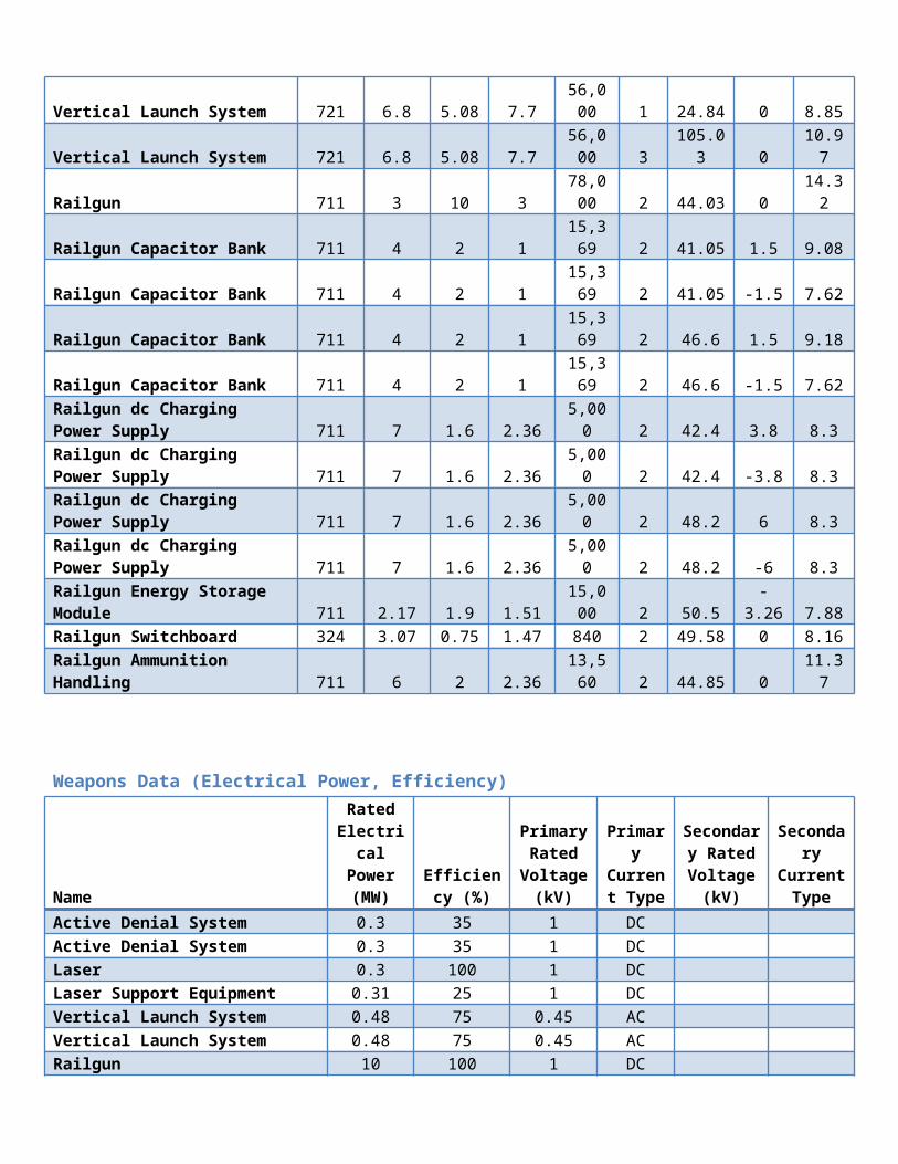
Mission Equipment DataTo place the design in the realm of future capabilities, we performed a survey of new weapon and sensor technologies in the world’s navies and selected several leading-edge technologies that would tax the power and cooling systems onboard the ship. Using publicly available information, a list of sensors, communications and weapons equipment along with the associated power and cooling system loads, efficiencies, weights and dimensions was compiled. Information on the sources of data and decisions made in sizing the equipment can be found in Appendix B of [Smart et al., 2017].
Some mission packages include the weapon or sensor and “support equipment.” Although the support equipment is represented as a single component, this component may in actuality be realized as several cabinets and functions. For the purposes of this notional vessel, we assume the mission packages to be “black boxes” that require power and cooling. Note that the weapon and support equipment may have separate efficiencies in order for the cooling system to remove heat produced in different locations.
The railgun system is comprised of the railgun, four energy storage components, four charging power supplies, and an electrical storage mechanism (ESM). The ESM stores incoming power from the bus during the railgun discharge cycle to maintain a constant load on the ship’s electrical distribution system of approximately 17 MW instead of inducing a reverse pulse during the discharge. There is also a relatively small ammunition handling equipment load. The S3D model of the rail gun mount is assigned an efficiency of 100% because this model does not address the cooling system for the railgun mount itself.
Weapons Data (Dimensions, Location)Identification Dimensions Location
Name SWBS Length (m)
Width (m)
Height (m)
Weight (kg)
Zone X (m) Y (m) Z (m)
Active Denial System 711 0.6 2 2 1,000 2 80.5 -5.6 19.83Active Denial System 711 0.6 2 2 1,000 2 80.5 5.6 19.83Laser 711 4 4 3 4,000 4 113.37 0 15.47Laser Support Equipment 711 6 4 3 4,000 3 112.64 0 11.69Vertical Launch System 721 6.8 5.08 7.7 56,000 1 24.84 0 8.85Vertical Launch System 721 6.8 5.08 7.7 56,000 3 105.03 0 10.97Railgun 711 3 10 3 78,000 2 44.03 0 14.32Railgun Capacitor Bank 711 4 2 1 15,369 2 41.05 1.5 9.08Railgun Capacitor Bank 711 4 2 1 15,369 2 41.05 -1.5 7.62Railgun Capacitor Bank 711 4 2 1 15,369 2 46.6 1.5 9.18Railgun Capacitor Bank 711 4 2 1 15,369 2 46.6 -1.5 7.62Railgun dc Charging Power Supply 711 7 1.6 2.36 5,000 2 42.4 3.8 8.3Railgun dc Charging Power Supply 711 7 1.6 2.36 5,000 2 42.4 -3.8 8.3Railgun dc Charging Power Supply 711 7 1.6 2.36 5,000 2 48.2 6 8.3Railgun dc Charging Power Supply 711 7 1.6 2.36 5,000 2 48.2 -6 8.3Railgun Energy Storage Module 711 2.17 1.9 1.51 15,000 2 50.5 -3.26 7.88Railgun Switchboard 324 3.07 0.75 1.47 840 2 49.58 0 8.16Railgun Ammunition Handling 711 6 2 2.36 13,560 2 44.85 0 11.37

Weapons Data (Electrical Power, Efficiency)
Name
Rated Electrical
Power (MW)
Efficiency (%)
Primary Rated
Voltage (kV)
Primary Current
Type
Secondary Rated
Voltage (kV)
Secondary Current
TypeActive Denial System 0.3 35 1 DCActive Denial System 0.3 35 1 DCLaser 0.3 100 1 DCLaser Support Equipment 0.31 25 1 DCVertical Launch System 0.48 75 0.45 ACVertical Launch System 0.48 75 0.45 ACRailgun 10 100 1 DCRailgun Capacitor Bank 3.58 98 1 DC 1 DCRailgun Capacitor Bank 3.58 98 1 DC 1 DCRailgun Capacitor Bank 3.58 98 1 DC 1 DCRailgun Capacitor Bank 3.58 98 1 DC 1 DCRailgun dc Charging Power Supply 4.16 98 12 DC 1 DCRailgun dc Charging Power Supply 4.16 98 12 DC 1 DCRailgun dc Charging Power Supply 4.16 98 12 DC 1 DCRailgun dc Charging Power Supply 4.16 98 12 DC 1 DCRailgun Energy Storage Module 17 98 12 DC 12 DCRailgun Switchboard 100 12 DCRailgun Ammunition Handling 0.4 100 1 DC
Sensor Data (Dimensions, Location)Identification Dimensions Location
Name SWBS Length (m)
Width (m)
Height (m)
Weight (kg)
Zone X (m) Y (m) Z (m)
Integrated Topside Array 410 2 1 1 2,000 2 72 -7.6 24.23Integrated Topside Array 410 2 1 1 2,000 2 72 7.6 24.23Integrated Topside Support Equipment 410 2.5 2.5 2.5 2,000 2 72 -5.82 22Integrated Topside Support Equipment 410 2.5 2.5 2.5 2,000 2 72 5.82 22Hull-mounted Sonar 461 5 5 1.5 30,000 1 4 0 0Sonar Support Equipment 461 10 2 5.3 15,000 1 14.19 0 3.85Towed-Array Sonar 461 3 6 2 14,000 4 148.61 3.5 8.12S-band Radar Array 456 4 1 4 10,000 2 55 -5 18.75S-band Radar Array 456 4 1 4 10,000 2 55 5 18.75S-band Radar Array 456 4 1 4 10,000 3 100 0 18.75X-band Radar Array 456 2.5 1 2.5 2,500 2 55.5 -3.85 23X-band Radar Array 456 2.5 1 2.5 2,500 2 55.5 3.85 23X-band Radar Array 456 2.5 1 2.5 2,500 3 99.5 0 23Radar Support Equipment 456 5 10 4 32,000 2 57.55 0 14.85Radar Support Equipment 456 5 5 4 16,000 3 95.33 0 14.85
Sensor Data (Electrical Power, Efficiency)
Name
Rated Electrical
Power (MW)
High Energy Power (MW)
Medium Energy Power (MW)
Low Energy Power (MW)
Efficiency (%)
Primary Rated
Voltage (kV)
Primary Current
TypeIntegrated Topside Array 1.5 1.5 0.38 0 33.33 1 DCIntegrated Topside Array 1.5 1.5 0.38 0 33.33 1 DCIntegrated Topside Support Equipment 1.5 75 1 DCIntegrated Topside Support Equipment 1.5 75 1 DCHull-mounted Sonar 0.3 100 1 DCHull-mounted Sonar Support Equipment 0.3 75 1 DCTowed-Array Sonar 0.15 75 1 DCS-band Radar Array 0.75 0.75 0.38 0.02 50 1 DCS-band Radar Array 0.75 0.75 0.38 0.02 50 1 DCS-band Radar Array 0.75 0.75 0.38 0.02 50 1 DCX-band Radar Array 0.24 0.24 0.12 0.01 50 1 DCX-band Radar Array 0.24 0.24 0.12 0.01 50 1 DCX-band Radar Array 0.24 0.24 0.12 0.01 50 1 DCRadar Support Equipment 2 60 1 DCRadar Support Equipment 1 60 1 DC

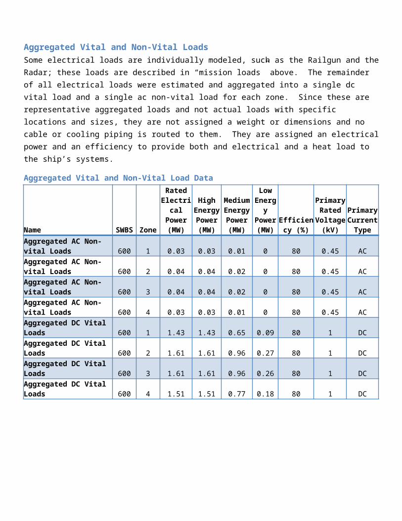
Aggregated Vital and Non-Vital LoadsSome electrical loads are individually modeled, such as the Railgun and the Radar; these loads are described in “mission loads” above. The remainder of all electrical loads were estimated and aggregated into a single dc vital load and a single ac non-vital load for each zone. Since these are representative aggregated loads and not actual loads with specific locations and sizes, they are not assigned a weight or dimensions and no cable or cooling piping is routed to them. They are assigned an electrical power and an efficiency to provide both and electrical and a heat load to the ship’s systems.
Aggregated Vital and Non-Vital Load Data
Name SWBS Zone
Rated Electrical
Power (MW)
High Energy Power (MW)
Medium Energy Power (MW)
Low Energy Power (MW)
Efficiency (%)
Primary Rated
Voltage (kV)
Primary Current
TypeAggregated AC Non-vital Loads 600 1 0.03 0.03 0.01 0 80 0.45 ACAggregated AC Non-vital Loads 600 2 0.04 0.04 0.02 0 80 0.45 ACAggregated AC Non-vital Loads 600 3 0.04 0.04 0.02 0 80 0.45 ACAggregated AC Non-vital Loads 600 4 0.03 0.03 0.01 0 80 0.45 ACAggregated DC Vital Loads 600 1 1.43 1.43 0.65 0.09 80 1 DCAggregated DC Vital Loads 600 2 1.61 1.61 0.96 0.27 80 1 DCAggregated DC Vital Loads 600 3 1.61 1.61 0.96 0.26 80 1 DCAggregated DC Vital Loads 600 4 1.51 1.51 0.77 0.18 80 1 DC

Power Generation Module (PGM) A power generation module (PGM) in this design is composed of an engine, a generator, a breaker and a rectifier.
The engines and generators were selected in order to meet the power requirements of the ship and to have generation capability in each zone. Thus, there is a Caterpillar C18 emergency diesel generator in zone 1, two LM2500+G4 gas turbine generators in zone 2, one LM2500+G4 and one LM500 gas turbine generator in zone 3, and one LM500 gas turbine generator in zone 4, for a total of 95MW of installed power.
The generators are dual-wound generators with a separate rectifier for each set of windings and thus can provide power to each bus separately.
The generation power of the generators is rated for 100oF; it is expected that the generator may produce significantly greater than 100% power for short periods of time, especially if the ambient temperature is low. Therefore, the rectifiers are rated for higher power than the generators with which they are associated.
An ac breaker is placed between the generator and rectifier.
Power Generation Module Data (Dimensions, Location)
Name SWBSHeight
(m)Width
(m)Length
(m)Weight
(kg) Zone X (m) Y (m) Z (m)Emergency Diesel Generator (EDG) 311 1.57 1.1 3.21 6,600 1 34.93 2.75 3.8LM2500+G4 Gas Turbine Generator 311 4 3.81 14.3 97,045 2 67.7 -2.5 3.19LM2500+G4 Gas Turbine Generator 311 4 3.81 14.3 97,045 2 67.7 2.5 3.19LM2500+G4 Gas Turbine Generator 311 4 3.81 14.3 97,045 3 93.13 -3 3.19LM500 Gas Turbine Generator 311 2.39 2.36 7.14 27,273 3 89.02 3 3.19LM500 Gas Turbine Generator 311 2.39 2.36 7.14 27,273 4 133.8 6.51 8.15EDG Breaker 311 0.4 0.4 0.4 25 1 31.99 2.63 5.16LM2500 Breaker 311 0.8 0.8 0.8 250 2 75.4 -4.5 5.02LM2500 Breaker 311 0.8 0.8 0.8 250 3 75.4 -4.5 3.8LM2500 Breaker 311 0.8 0.8 0.8 250 2 75.4 4.5 5.02LM2500 Breaker 311 0.8 0.8 0.8 250 3 75.4 4.5 3.8LM2500 Breaker 311 0.8 0.8 0.8 250 2 100.8 -4.5 5.02LM2500 Breaker 311 0.8 0.8 0.8 250 2 100.8 -4.5 3.8LM500 Breaker 311 0.6 0.6 0.6 50 3 93 3.55 5.02LM500 Breaker 311 0.6 0.6 0.6 50 4 93 3.55 3.8LM500 Breaker 311 0.6 0.6 0.6 50 3 138 8 10.02LM500 Breaker 311 0.6 0.6 0.6 50 4 138 8 8.8EDG Rectifier 311 2.36 3.4 1.6 2,550 1 31.9 2.59 2.88LM2500 Rectifier 311 2.36 1.6 5.5 5,730 2 64 -6 2.85LM2500 Rectifier 311 2.36 1.6 5.5 5,730 2 70.9 -6 2.85
LM2500 Rectifier 311 2.36 1.6 5.5 5,730 2 64 6 2.85LM2500 Rectifier 311 2.36 1.6 5.5 5,730 2 70.9 6 2.85LM2500 Rectifier 311 2.36 1.6 5.5 5,730 3 96.31 -6.5 2.85LM2500 Rectifier 311 2.36 1.6 5.5 5,730 3 89.88 -6.5 2.85LM500 Rectifier 311 2.36 1.6 3.4 2,910 3 91.7 5.38 2.85LM500 Rectifier 311 2.36 1.6 3.4 2,910 3 87.3 5.38 2.85LM500 Rectifier 311 2.36 1.6 3.4 2,910 4 132 3.54 8.5LM500 Rectifier 311 2.36 1.6 3.4 2,910 4 136.3 3.54 8.5
Power Generation Module Data (Electrical Power, Efficiency)
Name
Rated Electrical
Power (MW)
Rated Continuous
Current (kA)
Efficiency (%)
Primary Rated
Voltage (kV)
Primary Current
Type
Secondary Rated
Voltage (kV)
Secondary Current
TypeEmergency Diesel Generator (EDG) 0.55 var 6.9 ACLM2500+G4 Gas Turbine Generator 29 var 6.9 ACLM2500+G4 Gas Turbine Generator 29 var 6.9 ACLM2500+G4 Gas Turbine Generator 29 var 6.9 ACLM500 Gas Turbine Generator 3.7 var 6.9 ACLM500 Gas Turbine Generator 3.7 var 6.9 ACEDG Breaker 0.1 6.9 ACLM2500 Breaker 2.5 6.9 ACLM2500 Breaker 2.5 6.9 ACLM2500 Breaker 2.5 6.9 ACLM2500 Breaker 2.5 6.9 ACLM2500 Breaker 2.5 6.9 ACLM2500 Breaker 2.5 6.9 ACLM500 Breaker 0.5 6.9 ACLM500 Breaker 0.5 6.9 ACLM500 Breaker 0.5 6.9 ACLM500 Breaker 0.5 6.9 ACEDG Rectifier 0.66 98 6.9 AC 12 DCLM2500 Rectifier 17.4 98 6.9 AC 12 DCLM2500 Rectifier 17.4 98 6.9 AC 12 DCLM2500 Rectifier 17.4 98 6.9 AC 12 DCLM2500 Rectifier 17.4 98 6.9 AC 12 DCLM2500 Rectifier 17.4 98 6.9 AC 12 DCLM2500 Rectifier 17.4 98 6.9 AC 12 DCLM500 Rectifier 2.24 98 6.9 AC 12 DCLM500 Rectifier 2.24 98 6.9 AC 12 DCLM500 Rectifier 2.24 98 6.9 AC 12 DC

LM500 Rectifier 2.24 98 6.9 AC 12 DC
Specific Fuel ConsumptionLM2500+G4 Specific Fuel Consumption LM500 Specific Fuel Consumption Diesel Specific Fuel ConsumptionPower (MW) SFC (kg/Mj) Power (MW) SFC (kg/Mj) Power (MW) SFC (kg/Mj)
2 0.268 0.3 0.186 0.159 0.0668 0.155 0.9 0.124 0.184 0.064
20 0.072 1.5 0.093 0.272 0.06329 0.062 2.25 0.082 0.31 0.061
3.7 0.077 0.55 0.061

Power Distribution DataThe electrical distribution system is modeled after the proposed MVDC architecture circulated by the U.S. Navy [Doerry 2016] as depicted in Figure 3. Main bus distribution voltage is 12 kV (+-6kV). The notional ship described herein uses four electrical zones instead of six and is modified to accommodate the equipment selected for this ship design, but uses the same paradigm for distribution, e.g. cross-zone connections between ac load centers in adjacent zones, dedicated converters for electrical loads greater than 1 MW, and a combination of bus nodes, power conversion modules (PCM 1As), integrated power node centers (IPNCs) and ac Load Centers (ACLCs) to provide the required power supply. The resultant power distribution system is depicted in Figure 4. Note that all loads are individually switched; although some ports on the Bus Nodes, ACLCs and IPNCs appear to have multiple loads connected to a single port, this is a rendering problem and does not indicate that the loads are switched as a group. Similarly, cables that appear coincident are actually separate.
Figure 3. Proposed Navy distribution system [Doerry 2016]

Electrical View
Figure 4. Notional Ship Electrical Distribution System, from S3D Model (model simplified to make connections more clear).

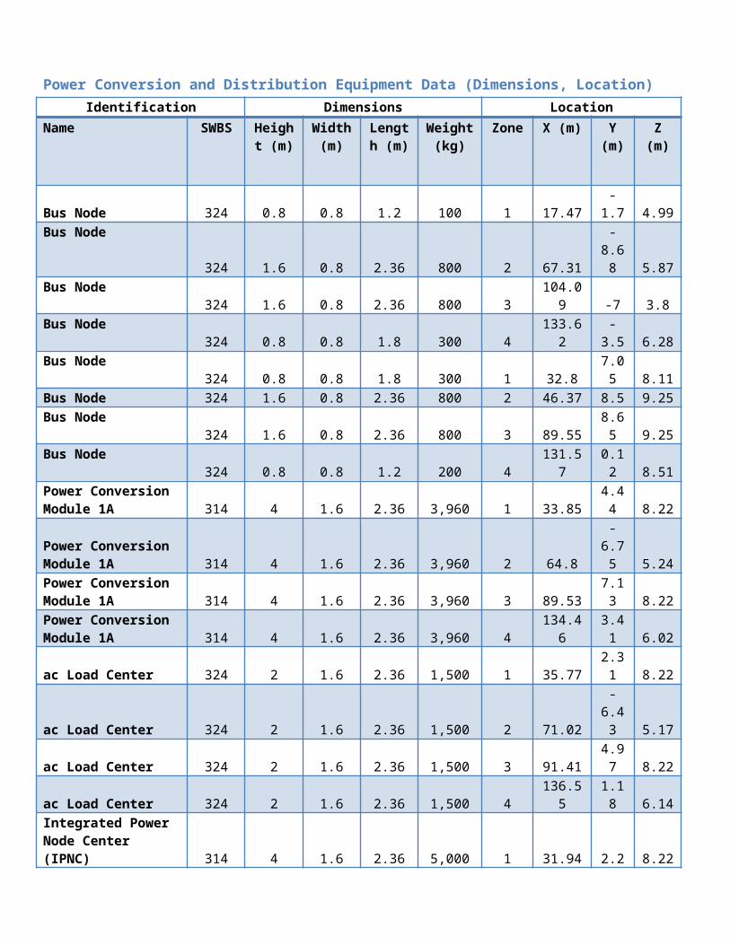
Power Conversion and Distribution EquipmentBus nodes provide dc disconnect capability for each line. They are sized for the number of connections that are made.
The PCM1A (power conversion module 1A) converts power from bus voltage to an internal 1kVdc bus, then provides power at1kVdc to the IPNC via a disconnect, and power at 450Vac to the ACLC via a circuit breaker.
The ACLC (ac Load Center) is a traditional 450 Vac switchboard, with a connection to the next zone load center for casualty power operations.
The IPNC (integrated power node center) supplies power to loads with special power needs, such as dc, 400Hz ac, or variable speed motors, and supplies power to un-interruptible loads; thus, it contains energy storage for about one second.
In normal operations, the ACLC and IPNC are fed from the PCM1A in the same zone. If a casualty exists that prevents this, power is provided from the ACLC in the adjacent zone to the in-zone ACLC and then to the IPNC.
We assume that the flow of power throughout the distribution system is controlled by the power electronics. No-load dc disconnects are included to provide galvanic isolation where needed.
Sizing of all power conversion equipment in this model is adapted from [Soltau et al., 2014]. A summary table for sizing is shown below.
Nominal Power Converter Sizing Chartdc/ac or ac/dc
Power Rating (MW) Weight (kg)
Length (m)
Depth (m)
Height (m)
1 2550 3.4 1.6 2.362 2730 3.4 1.6 2.363 2910 3.4 1.6 2.364 3090 3.4 1.6 2.366 3720 4 1.6 2.368 3780 4 1.6 2.3610 3900 4 1.6 2.3612 3960 4 1.6 2.3614 5610 5.5 1.6 2.3618 5730 5.5 1.6 2.3622 6438 6.4 1.6 2.3624 6618 6.4 1.6 2.36

Power Conversion and Distribution Equipment Data (Dimensions, Location)Identification Dimensions Location
Name SWBS Height (m)
Width (m)
Length (m)
Weight (kg)
Zone X (m) Y (m)
Z (m)
Bus Node 324 0.8 0.8 1.2 100 1 17.47 -1.7 4.99Bus Node 324 1.6 0.8 2.36 800 2 67.31 -8.68 5.87Bus Node 324 1.6 0.8 2.36 800 3 104.09 -7 3.8Bus Node 324 0.8 0.8 1.8 300 4 133.62 -3.5 6.28Bus Node 324 0.8 0.8 1.8 300 1 32.8 7.05 8.11Bus Node 324 1.6 0.8 2.36 800 2 46.37 8.5 9.25Bus Node 324 1.6 0.8 2.36 800 3 89.55 8.65 9.25Bus Node 324 0.8 0.8 1.2 200 4 131.57 0.12 8.51Power Conversion Module 1A 314 4 1.6 2.36 3,960 1 33.85 4.44 8.22Power Conversion Module 1A 314 4 1.6 2.36 3,960 2 64.8 -6.75 5.24Power Conversion Module 1A 314 4 1.6 2.36 3,960 3 89.53 7.13 8.22Power Conversion Module 1A 314 4 1.6 2.36 3,960 4 134.46 3.41 6.02ac Load Center 324 2 1.6 2.36 1,500 1 35.77 2.31 8.22ac Load Center 324 2 1.6 2.36 1,500 2 71.02 -6.43 5.17ac Load Center 324 2 1.6 2.36 1,500 3 91.41 4.97 8.22ac Load Center 324 2 1.6 2.36 1,500 4 136.55 1.18 6.14Integrated Power Node Center (IPNC) 314 4 1.6 2.36 5,000 1 31.94 2.2 8.22Integrated Power Node Center (IPNC) 314 4 1.6 2.36 5,000 2 62.88 -5.25 1.9Integrated Power Node Center (IPNC) 314 4 1.6 2.36 5,000 3 87.57 4.92 8.22Integrated Power Node Center (IPNC) 314 4 1.6 2.36 5,000 4 132.42 1.13 6.01Radar dc/dc Converter 314 4 1.6 2.36 5,000 3 95.33 0 11.52Radar dc/dc Converter 314 1.6 7 2.36 5,000 2 61.53 0 14Integrated Topside dc/dc Converter 314 4 1.6 2.36 5,000 2 72 -5.82 18.5Integrated Topside dc/dc Converter 314 4 1.6 2.36 5,000 2 72 5.82 18.5

Although the S3D models for converters allow efficiency to vary with load, the notional baseline converters were modeled with a constant 98% efficiency. Switches and switchboards are ideal (no losses).
Power Conversion and Distribution Equipment Data (Electrical Power)
Name
Rated Electrical
Power (MW)
Rated Continuous
Current (kA)
Efficiency (%)
Primary Rated
Voltage (kV)
Primary Current
Type
Secondary Rated
Voltage (kV)
Secondary Current
TypeBus Node 0.1 100 12 DCBus Node 5 100 12 DCBus Node 5 100 12 DCBus Node 1 100 12 DCBus Node 1 100 12 DCBus Node 5 100 12 DCBus Node 5 100 12 DCBus Node 0.5 100 12 DCPower Conversion Module 1A 10.64 98 12 DC var varPower Conversion Module 1A 10.64 98 12 DC var varPower Conversion Module 1A 9.17 98 12 DC var varPower Conversion Module 1A 9.17 98 12 DC var varac Load Center 7.82 100 0.45 AC 0.45 ACac Load Center 7.45 100 0.45 AC 0.45 ACac Load Center 5.14 100 0.45 AC 0.45 ACac Load Center 7.14 100 0.45 AC 0.45 ACIntegrated Power Node Center (IPNC) 2.77 98 var var var varIntegrated Power Node Center (IPNC) 3.13 98 var var var varIntegrated Power Node Center (IPNC) 3.95 98 var var var varIntegrated Power Node Center (IPNC) 1.99 98 var var var varRadar dc/dc Converter 1.65 98 12 DC 1 DCRadar dc/dc Converter 3.3 98 12 DC 1 DCIntegrated Topside dc/dc Converter 2 98 12 DC 1 DCIntegrated Topside dc/dc Converter 2 98 12 DC 1 DC

Cable Data The cables in this model are based on Caledonian Medium Voltage Cables for Marine Applications [Caledonian 2016].
Cable Data (Location, Dimensions)Name SWBS Zone Length
(m)Connecting Equipment
z1_CAB_ACLC_to_IPNC 321 1 3.94 z1_ACLC z1_IPNCz1_CAB_Chiller 321 1 9.14 z1_ACLC z1_CHILLERz1_CAB_Chiller_CHWPump 321 1 12.4 z1_ACLC z1_CHILLER_P_CHW_PUMPz1_CAB_Chiller_SWPump 321 1 9.39 z1_ACLC z1_CHILLER_P_SW_PUMPz1_CAB_DC_InZone_S 321 1 3.77 z1_BUS_S z1_PCM1A_Sz1_CAB_EDG_AC 321 1 4.42 z1_EDG z1_BRK_EDGz1_CAB_EDG_DC_P 321 1 19.72 z1_EDG_RECT z1_BUS_Pz1_CAB_EDG_DC_S 321 1 9.46 z1_EDG_RECT z1_BUS_Sz1_CAB_PCM1A_to_ACLC 321 1 2.6 z1_PCM1A_S z1_ACLCz1_CAB_PCM1A_to_IPNC 321 1 3.1 z1_PCM1A_S z1_IPNCz1_CAB_SONAR 321 1 22.97 z1_IPNC z1_SONAR_SUPPORT_EQz1_CAB_VLS 321 1 9.19 z1_IPNC z1_VLSz1_z2_CAB_ACLC_DaisyChain 321 1 / 2 44.15 z1_ACLC z2_ACLCz1_z2_CAB_P 321 1 / 2 57.13 z1_BUS_P z2_BUS_Pz1_z2_CAB_S 321 1 / 2 15.11 z1_BUS_S z2_BUS_Sz2_CAB_ACLC_to_IPNC 321 2 12.6 z2_ACLC z2_IPNCz2_CAB_ADS_P 321 2 35.89 z2_IPNC z2_ADS_Pz2_CAB_ADS_S 321 2 45.12 z2_ACLC z2_ADS_Sz2_CAB_Chiller_P 321 2 17.93 z2_ACLC z2_CHILLER_Pz2_CAB_Chiller_S 321 2 26.08 z2_ACLC z2_CHILLER_Sz2_CAB_ChillerPCHWPump 321 2 22.96 z2_ACLC z2_CHILLER_P_CHW_PUMPz2_CAB_ChillerPSWPump 321 2 20.08 z2_ACLC z2_CHILLER_P_SW_PUMPz2_CAB_ChillerSCHWPump 321 2 24.79 z2_ACLC z2_CHILLER_S_CHW_PUMPz2_CAB_ChillerSSWPump 321 2 22.01 z2_ACLC z2_CHILLER_S_SW_PUMPz2_CAB_DC_InZone_P 321 2 4.02 z2_BUS_P z2_PCM1A_Pz2_CAB_InTopP_P 321 2 19.43 z2_BUS_P z2_InTop_Eqpt_Pz2_CAB_InTopP_S 321 2 36.37 z2_BUS_S z2_InTop_Eqpt_Pz2_CAB_InTopS_P 321 2 31.07 z2_BUS_P z2_InTop_Eqpt_Sz2_CAB_InTopS_S 321 2 48.01 z2_BUS_S z2_InTop_Eqpt_Sz2_CAB_LM2500P_AC_P1 321 2 9.44 z2_LM2500_P z2_BRK_LM2500_P1z2_CAB_LM2500P_AC_P2 321 9.26 z2_LM2500_P z2_BRK_LM2500_P2z2_CAB_LM2500P_DC_P 321 2 3.72 z2_LM2500_RECT_P z2_BUS_Pz2_CAB_LM2500P_DC_S 321 2 42.68 z2_LM2500_RECT_P z2_BUS_Sz2_CAB_LM2500S_AC_S1 321 2 9.44 z2_LM2500_S z2_BRK_LM2500_S1z2_CAB_LM2500S_AC_S2 321 9.26 z2_LM2500_S z2_BRK_LM2500_S2z2_CAB_LM2500S_DC_P 321 2 17.65 z2_LM2500_RECT_S z2_BUS_Pz2_CAB_LM2500S_DC_S 321 2 27.21 z2_LM2500_RECT_S z2_BUS_Sz2_CAB_PCM1A_to_ACLC 321 2 6.6 z2_PCM1A_P z2_ACLCz2_CAB_PCM1A_to_IPNC 321 2 4.66 z2_PCM1A_P z2_ACLCz2_CAB_PMM_P 321 2 20.38 z2_BUS_P z2_PMM_Drive_S

z2_CAB_PMM_S 321 2 47.08 z2_BUS_S z2_PMM_Drive_Sz2_CAB_Radar_P 321 2 21.75 z2_BUS_P z2_DCDC_Radarz2_CAB_Radar_S 321 2 27.14 z2_BUS_S z2_DCDC_Radarz2_CAB_railgun_ammo_handling 321 2 31.4 z2_IPNC z2_Railgun_Ammo_Handlingz2_CAB_Railgun_P 321 2 27.04 z2_BUS_P z2_SWT_Railgunz2_CAB_Railgun_S 321 2 11.75 z2_BUS_S z2_SWT_Railgunz2_z3_CAB_P 321 2 / 3 38 z2_BUS_P z3_BUS_Pz2_z3_CAB_S 321 2 / 3 43.33 z2_BUS_S z3_BUS_Sz3_CAB_ACLC_to_IPNC 321 3 3.89 z3_ACLC z3_IPNCz3_CAB_Chiller 321 3 17.82 z3_ACLC z3_CHILLER_Sz3_CAB_Chiller_CHWPump 321 3 20.2 z3_ACLC z3_CHILLER_S_CHW_PUMPz3_CAB_Chiller_SWPump 321 3 17.46 z3_ACLC z3_CHILLER_S_SW_PUMPz3_CAB_DC_InZone_S 321 3 2.57 z3_BUS_S z3_PCM1A_Sz3_CAB_LM2500_AC_S1 321 3 8.91 z3_LM2500_P z3_BRK_LM2500_P1z3_CAB_LM2500_AC_S2 321 8.73 z3_LM2500_P z3_BRK_LM2500_P2z3_CAB_LM2500_DC_P 321 3 13.3 z3_LM2500_RECT_P z3_BUS_Pz3_CAB_LM2500_DC_S 321 3 24.95 z3_LM2500_RECT_P z3_BUS_Sz3_CAB_LM500P_AC_P1 321 3 5.78 z3_LM500_S z3_BRK_LM500_S1z3_CAB_LM500P_AC_P2 321 5.32 z3_LM500_S z3_BRK_LM500_S2z3_CAB_LM500P_DC_P 321 3 29.63 z3_LM500_RECT_S z3_BUS_Pz3_CAB_LM500P_DC_S 321 3 7.54 z3_LM500_RECT_S z3_BUS_Sz3_CAB_PCM1A_to_ACLC 321 3 2.78 z3_PCM1A_S z3_ACLCz3_CAB_PCM1A_to_IPNC 321 3 2.91 z3_PCM1A_S z3_IPNCz3_CAB_PMM_P 321 3 9.28 z3_PMM_Drive_P z3_BUS_Pz3_CAB_PMM_S 321 3 28.86 z3_PMM_Drive_P z3_BUS_S
z3_CAB_Radar_P 321 3 22.32z3_RADAR_Support_Eq z3_BUS_P
z3_CAB_Radar_S 321 3 15.54z3_RADAR_Support_Eq z3_BUS_S
z3_CAB_VLS 321 3 23.65 z3_IPNC z3_VLSz3_z4_CAB_ACLC_DaisyChain 321 3 / 4 48.48 z3_ACLC z4_ACLCz3_z4_CAB_P 321 3 / 4 34.16 z3_BUS_P z4_BUS_Pz3_z4_CAB_S 321 3 / 4 50.65 z3_BUS_S z4_BUS_Sz4_CAB_ACLC_to_IPNC 321 4 4.31 z4_ACLC z4_IPNCz4_CAB_Chiller 321 4 7.06 z4_ACLC z4_CHILLER_Pz4_CAB_Chiller_CHWPump 321 4 3.93 z4_ACLC z4_CHILLER_S_CHW_PUMPz4_CAB_Chiller_SWPump 321 4 3.03 z4_ACLC z4_CHILLER_S_SW_PUMPz4_CAB_DC_InZone_P 321 4 8.01 z4_BUS_P z4_PCM1A_Pz4_CAB_Laser_P 321 3 26.59 z3_IPNC z3_laser_support_eqz4_CAB_LM500_AC_S1 321 4 6.03 z4_LM500_S z4_BRK_LM500_S1z4_CAB_LM500_AC_S2 321 5.58 z4_LM500_S z4_BRK_LM500_S2z4_CAB_LM500S_DC_P 321 4 4.89 z4_LM500_RECT_S z4_BUS_Pz4_CAB_LM500S_DC_S 321 4 2.38 z4_LM500_RECT_S z4_BUS_Sz4_CAB_MFTA_P 321 4 19.5 z4_MFTA_and_Eq z4_IPNCz4_CAB_PCM1A_to_ACLC 321 4 3.01 z4_PCM1A_P z4_ACLCz4_CAB_PCM1A_to_IPNC 321 4 3.27 z4_PCM1A_P z4_IPNC

Cable Data (Electrical Power, Weight)Name Rated
Voltage (kV)
Current Type
Number of
Cables in
Bundle
Rated Continuous Current per
Cable (A)
Total Rated Continuous Current (A)
Weight Per Unit
Length (kg/m)
Weight (kg)
z1_CAB_ACLC_to_IPNC 0.45 AC 5 780 3900 33.05 390.45z1_CAB_Chiller 0.45 AC 2 890 1780 16.34 448.21z1_CAB_Chiller_CHWPump 0.45 AC 1 127 127 1.02 37.94z1_CAB_Chiller_SWPump 0.45 AC 1 127 127 1.02 28.74z1_CAB_DC_InZone_S 12 DC 2 522 1044 7.45 56.11z1_CAB_EDG_AC 6.9 AC 1 127 127 1.02 13.53z1_CAB_EDG_DC_P 12 DC 1 127 127 1.02 40.22z1_CAB_EDG_DC_S 12 DC 1 127 127 1.02 19.29z1_CAB_PCM1A_to_ACLC 0.45 AC 12 890 10680 98.04 766.03z1_CAB_PCM1A_to_IPNC 1 DC 4 780 3120 26.44 164.04z1_CAB_SONAR 1 DC 1 522 522 3.72 171.14z1_CAB_VLS 0.45 AC 1 780 780 6.61 182.25z1_z2_CAB_ACLC_DaisyChain 0.45 AC 10 890 8900 81.7 10822z1_z2_CAB_P 12 DC 1 127 127 1.02 116.55z1_z2_CAB_S 12 DC 2 522 1044 7.45 225.16
z2_CAB_ACLC_to_IPNC 0.45 AC 5 890 4450 40.851544.5
8z2_CAB_ADS_P 1 DC 1 389 389 2.55 183.04z2_CAB_ADS_S 1 DC 1 389 389 2.55 230.13z2_CAB_Chiller_P 0.45 AC 2 890 1780 16.34 879.09z2_CAB_Chiller_S 0.45 AC 2 890 1780 16.34 1278.6z2_CAB_ChillerPCHWPump 0.45 AC 1 127 127 1.02 70.26z2_CAB_ChillerPSWPump 0.45 AC 1 127 127 1.02 61.44z2_CAB_ChillerSCHWPump 0.45 AC 1 127 127 1.02 75.86z2_CAB_ChillerSSWPump 0.45 AC 1 127 127 1.02 67.35z2_CAB_DC_InZone_P 12 DC 2 522 1044 7.45 59.93z2_CAB_InTopP_P 12 DC 1 242 242 1.6 61.98z2_CAB_InTopP_S 12 DC 1 242 242 1.6 116.02z2_CAB_InTopS_P 12 DC 1 242 242 1.6 99.11z2_CAB_InTopS_S 12 DC 1 242 242 1.6 153.15z2_CAB_LM2500P_AC_P1 6.9 AC 2 780 1560 13.22 374.21z2_CAB_LM2500P_AC_P2 6.9 AC 2 780 1560 13.22 367.32z2_CAB_LM2500P_DC_P 12 DC 4 780 3120 26.44 196.75
z2_CAB_LM2500P_DC_S 12 DC 4 780 3120 26.442257.0
5z2_CAB_LM2500S_AC_S1 6.9 AC 2 780 1560 13.22 374.21z2_CAB_LM2500S_AC_S2 6.9 AC 2 780 1560 13.22 367.37z2_CAB_LM2500S_DC_P 12 DC 4 780 3120 26.44 933.34
z2_CAB_LM2500S_DC_S 12 DC 4 780 3120 26.441438.6
8
z2_CAB_PCM1A_to_ACLC 0.45 AC 11 890 9790 89.871780.7
2
z2_CAB_PCM1A_to_IPNC 1 DC 4 890 3560 32.68 304.76
z2_CAB_PMM_P 12 DC 5 780 3900 33.051346.8
3z2_CAB_PMM_S 12 DC 5 780 3900 33.05 3111.7z2_CAB_Radar_P 12 DC 1 339 339 2.24 97.23z2_CAB_Radar_S 12 DC 1 339 339 2.24 121.3z2_CAB_railgun_ammo_handling 1 DC 1 522 522 3.72 233.93z2_CAB_Railgun_P 12 DC 2 890 1780 16.34 883.78z2_CAB_Railgun_S 12 DC 2 890 1780 16.34 384.04
z2_z3_CAB_P 12 DC 6 890 5340 49.023725.4
9
z2_z3_CAB_S 12 DC 6 890 5340 49.024248.2
7z3_CAB_ACLC_to_IPNC 0.45 AC 6 890 5340 49.02 572.06z3_CAB_Chiller 0.45 AC 2 890 1780 16.34 873.43z3_CAB_Chiller_CHWPump 0.45 AC 1 127 127 1.02 61.81z3_CAB_Chiller_SWPump 0.45 AC 1 127 127 1.02 53.43z3_CAB_DC_InZone_S 12 DC 1 780 780 6.61 33.98z3_CAB_LM2500_AC_S1 6.9 AC 2 780 1560 13.22 353.19z3_CAB_LM2500_AC_S2 6.9 AC 2 780 1560 13.22 346.3z3_CAB_LM2500_DC_P 12 DC 4 780 3120 26.44 703.34
z3_CAB_LM2500_DC_S 12 DC 4 780 3120 26.441319.2
7z3_CAB_LM500P_AC_P1 6.9 AC 1 196 196 1.32 22.89z3_CAB_LM500P_AC_P2 6.9 AC 1 196 196 1.32 21.08z3_CAB_LM500P_DC_P 12 DC 1 389 389 2.55 151.13z3_CAB_LM500P_DC_S 12 DC 1 389 389 2.55 38.45z3_CAB_PCM1A_to_ACLC 0.45 AC 8 890 7120 65.36 544.19z3_CAB_PCM1A_to_IPNC 1 DC 5 890 4450 40.85 237.37z3_CAB_PMM_P 12 DC 5 780 3900 33.05 613.68
z3_CAB_PMM_S 12 DC 5 780 3900 33.051907.5
1z3_CAB_Radar_P 12 DC 1 196 196 1.32 58.92z3_CAB_Radar_S 12 DC 1 196 196 1.32 41.02z3_CAB_VLS 0.45 AC 1 780 780 6.61 469.04
z3_z4_CAB_ACLC_DaisyChain 0.45 AC 7 890 6230 57.198317.8
2z3_z4_CAB_P 12 DC 1 780 780 6.61 451.55z3_z4_CAB_S 12 DC 1 389 389 2.55 258.31z4_CAB_ACLC_to_IPNC 0.45 AC 3 890 2670 24.51 316.77z4_CAB_Chiller 0.45 AC 2 890 1780 16.34 346.03z4_CAB_Chiller_CHWPump 0.45 AC 1 127 127 1.02 12.04z4_CAB_Chiller_SWPump 0.45 AC 1 127 127 1.02 9.27z4_CAB_DC_InZone_P 12 DC 1 780 780 6.61 105.94z4_CAB_Laser_P 1 DC 2 780 1560 13.22 703.11z4_CAB_LM500_AC_S1 6.9 AC 1 196 196 1.32 23.88z4_CAB_LM500_AC_S2 6.9 AC 1 196 196 1.32 22.08z4_CAB_LM500S_DC_P 12 DC 1 389 389 2.55 24.93

z4_CAB_LM500S_DC_S 12 DC 1 389 389 2.55 12.13z4_CAB_MFTA_P 1 DC 1 196 196 1.32 51.47z4_CAB_PCM1A_to_ACLC 0.45 AC 11 890 9790 89.87 811.07z4_CAB_PCM1A_to_IPNC 1 DC 3 690 2070 16.26 106.38

Thermal System Data
Thermal viewDiagram to be added
Cooling Equipment Data (Dimensions, Location)Identification Dimensions Location
Name SWBSLength
(m)Width
(m)Height
(m)Weight
(kg) Zone X (m) Y (m) Z (m)Chiller 514 2.9 2.3 5.7 38500 1 34.18 -2.78 3.66Chiller 514 2.9 2.3 5.7 38500 2 56.16 -3.97 2.46Chiller 514 2.9 2.3 5.7 38500 2 133.81 -4.11 6.22Chiller 514 2.9 2.3 5.7 38500 3 56.17 4.19 2.46Chiller 514 2.9 2.3 5.7 38500 4 105.19 3.73 5.42Seawater Pump 514 1 1 2 1000 1 36.91 -0.68 1.81Seawater Pump 514 1 1 2 1000 2 58.37 -1.22 1.81Seawater Pump 514 1 1 2 1000 2 58.49 0.83 1.81Seawater Pump 514 1 1 2 1000 3 104.16 6 3.4Seawater Pump 514 1 1 2 1000 4 136.5 -1.13 4.9Chilled Water Pump 514 1 1 2 1000 1 31.61 -0.66 1.81Chilled Water Pump 514 1 1 2 1000 2 55.76 -0.95 1.81Chilled Water Pump 514 1 1 2 1000 2 55.85 0.97 1.81Chilled Water Pump 514 1 1 2 1000 3 106.9 6 3.4Chilled Water Pump 514 1 1 2 1000 4 134.99 -1.09 4.9
Cooling Equipment Data (Electrical Power, Efficiency)
Name
Rated Electrical
Power (MW)
Efficiency (%)
Rated Voltage
(kV)Current
Type
Coefficient of
PerformanceChiller 3.87 1.1 0.45 ACChiller 3.87 1.1 0.45 ACChiller 3.87 1.1 0.45 ACChiller 3.87 1.1 0.45 ACChiller 3.87 1.1 0.45 ACSeawater Pump 0.08 80 0.45 ACSeawater Pump 0.08 80 0.45 ACSeawater Pump 0.08 80 0.45 ACSeawater Pump 0.08 80 0.45 ACSeawater Pump 0.08 80 0.45 ACChilled Water Pump 0.08 80 0.45 ACChilled Water Pump 0.08 80 0.45 ACChilled Water Pump 0.08 80 0.45 ACChilled Water Pump 0.08 80 0.45 ACChilled Water Pump 0.08 80 0.45 AC

Mission Definition
Static Mission ConditionsFour static mission conditions are defined as follows. These missions are intended for quasi-static system analysis for such evaluations as annual fuel usage.
Equipment Peacetime Cruise
Sprint to
Station
Battle Anchor
Active Denial System off off high lowLaser off medium high offRailgun off off high offVertical Launch System off off high offIntegrated Topside medium medium high mediumRadar medium high high lowSonar off off on offTowed-Array Sonar off off off offAggregated AC Non-vital Loads high medium medium highAggregated DC Vital Loads medium high high mediumShip Speed 15 kts 31 kts 8 kts 0 kts
Dynamic Mission ScenarioAn example dynamic mission scenario. This scenario is intended for dynamic system evaluations.
Equipment Initial state
Active Denial System standbyLaser standbyRailgun standbyVertical Launch System standbyIntegrated Topside highRadar highSonar onTowed-Array Sonar offAggregated AC Non-vital Loads mediumAggregated DC Vital Loads highShip Speed 8 kts
Beginning in the initial state indicated above, flow through the following sequence:
Charge railgun (5 seconds) Fire railgun (1 second) Charge railgun (5 seconds) Fire railgun (1 second) Increase speed to 25 kts Fire laser (15 seconds)
Fault Scenarios (expand description)

These fault scenarios are intended for dynamic system testing. Since S3D is currently a quasi-static analysis tool, fault testing is not applicable in that environment beyond manually opening the appropriate breakers or disconnects and determining whether power is available from a different source.
Example fault scenario 1: Beginning in the Sprint to Station condition described above, a fault develops in the cable leading from the zone 2 port bus node to the zone 2 dc/dc converter for the radar. This fault requires isolation of the cable from the bus node and the converter, and requires re-alignment of power to the radar from the starboard bus.
Example fault scenario 2: Beginning in the Sprint to Station condition described above, a fault develops in the zone 3 starboard bus node, requiring isolation of all connections to the bus node. This will require re-routing of power into zone three from the port bus; since the PCM1A in Zone 3 is connected to the starboard bus, power must be fed to in-zone loads via the ACLC in Zone 4. Additionally, the generators must deliver power to the starboard bus only and the radars and propulsion motor in zone 3 must receive power from the starboard bus.
ReferencesCaledonian, “NEK Offshore & Marine Cable”, 2016 http://www.caledonian-cables.com/product/Marine_Cables/marine_cable.html
N. Doerry, “MVDC System Stability”, Controls Workshop, The University of New Mexico, July 28, 2016.
R. Smart, J. Chalfant, J. Herbst, B. Langland, A. Card, R. Leonard, A. Gattozzi, “Task 1.4.3 Using S3D to Analyze Ship System Alternatives for a 100 MW 10,000 ton Surface Combatant”, ESRDC Report, April 2017.
Soltau, N.; Lenke, R. U.; de Doncker, R. W., “High-Power DC-DC Converter”, E.ON Energy Research Center Series Volume 5, Issue 5, 2014.

Figure 5. Example Fault Scenario 1
x

Figure 6. Example Fault Scenario 2
x