introduction to x-ray diffractionmeter › geology › wp-content › uploads › sites ›...
TRANSCRIPT

Introduction to XIntroduction to X--ray ray DiffractionmeterDiffractionmeterby Miguel Santiago, Scientific Instrumentation Specialist
University of Puerto Rico University of Puerto Rico –– MayagMayagüüezez CampusCampusDepartment of GeologyDepartment of GeologyXX--ray / Microanalysis Laboratory ray / Microanalysis Laboratory F F -- 304304

1. Introduction1. Introduction

1.1 History1.1 History
Wilhelm Conrad Wilhelm Conrad RRööntgenntgen discovered 1895 the Xdiscovered 1895 the X--rays. rays. 1901 he was honored by the Noble prize for physics. 1901 he was honored by the Noble prize for physics. In 1995 the German Post edited a stamp, dedicated In 1995 the German Post edited a stamp, dedicated to him.to him.

X-RAYS1895- Roentgen discovers X-raysX-rays are high-frequency electromagnetic radiation with energy intermediate between far-UV and gamma ray regions. This leads to development in numerous fields, particularly medical.
1911- Barkla recognized characteristic radiationThis scientist recognizes that x-rays emitted from different elements produce x-rays of different energy and wavelength.
1.2 History1.2 History

1.2 Characteristics of X1.2 Characteristics of X--raysrays
X-ray was the name given to the highly penetrating rays which emanated when high energy electrons struck a metal target. Within a short time of their discovery, they were being used in medical facilities to image broken bones. We now know that they are high frequency electromagnetic rays which are produced when the electrons are suddenly decelerated - these rays are called bremsstrahlungradiation, or "braking radiation".

1.2 Characteristics of X1.2 Characteristics of X--raysrays
"Bremsstrahlung" means "braking radiation" and is retained from the original German to describe the radiation which is emitted when electrons are decelerated or "braked" when they are fired at a metal target.Accelerated charges give off electromagnetic radiation, and when the energy of the bombarding electrons is high enough, that radiation is in the x-ray region of the electromagnetic spectrum.It is characterized by a continuous distribution of radiation which becomes more intense and shifts toward higher frequencies when the energy of the bombarding electrons is increased.
The curves in the are from the 1918 data of Ulrey, who bombarded tungsten targets with electrons of four different energies.

1.2 Characteristics of X1.2 Characteristics of X--raysrays
X-rays are also produced when electrons make transitions between lower atomic energy levels in heavy elements. X-rays produced in this way have have definite energies just like other line spectra from atomic electrons. They are called characteristic x-rays since they have energies determined by the atomic energy levels.In interactions with matter, x-rays are ionizing radiation and produce physiological effects which are not observed with any exposure of non-ionizing radiation, such as the risk of mutations or cancer in tissue.

1.2 Characteristics of X1.2 Characteristics of X--raysrays
XX--rays (like all radiation) can be rays (like all radiation) can be viewed as waves or particles.viewed as waves or particles.Transverse electromagnetic wave Transverse electromagnetic wave –– electr ic f ie ldelectr ic f ie ld is important is important (interacts with electrons), but the (interacts with electrons), but the magnetic fieldmagnetic field is not important.is not important.
• The wavelength λ is very short (from ~ 0.1 nm to ~ 1.0 nm).

1.2 Characteristics of X1.2 Characteristics of X--raysrays
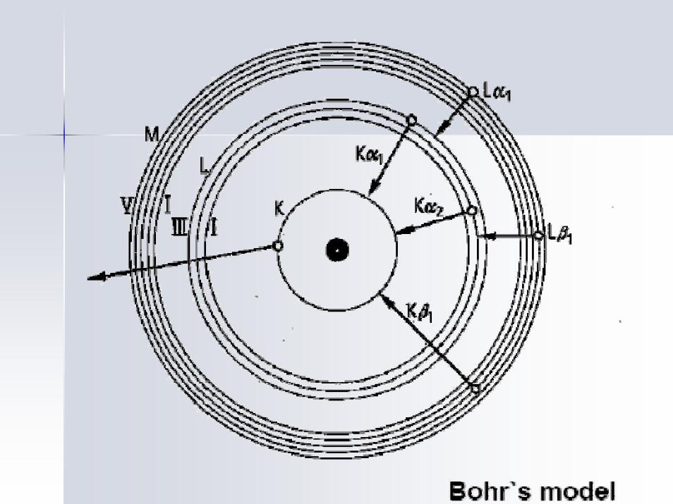
Characteristic x-rays are emitted from heavy elements when their electrons make transitions between the lower atomic energy levels. The characteristic x-rays emission which shown as two sharp peaks in the illustration at left occur when vacancies are produced in the n=1 or K-shell of the atom and electrons drop down from above to fill the gap. The x-rays produced by transitions from the n=2 to n=1 levels are called K-alpha x-rays, and those for the n=3->1 transiton are called K-beta x-rays. Transitions to the n=2 or L-shell are designated as L x-rays (n=3->2 is L-alpha, n=4->2 is L-beta, etc. ). The continuous distribution of x-rays which forms the base for the two sharp peaks at left is called "bremsstrahlung" radiation.

1.2 Characteristics of X1.2 Characteristics of X--raysrays
X-ray production typically involves bombarding a metal target in an x-ray tube with high speed electrons which have been accelerated by tens to hundreds of kilovolts of potential. The bombarding electrons can eject electrons from the inner shells of the atoms of the metal target. Those vacancies will be quickly filled by electrons dropping down from higher levels, emitting x-rays with sharply defined frequencies associated with the difference between the atomic energy levels of the target atoms. The frequencies of the characteristic x-rays can be predicted from the Bohr model . Moseley measured the frequencies of the characteristic x-rays from a large fraction of the elements of the periodic table and produces a plot of them which is now called a"Moseley plot". Characteristic x-rays are used for the investigation of crystal structure by x-ray diffraction. Crystal lattice dimensions may be determined with the use of Bragg's law in a Bragg spectrometer.

1.2 Characteristics of X1.2 Characteristics of X--raysraysWhen the square root of the frequencies of the characteristic x-raysfrom the elements is plotted against the atomic number, a straight line is obtained. In his early 20's, Moseley measured and plotted the x-ray frequencies for about 40 of the elements of the periodic table. He showed that the K-alpha x-rays followed a straight line when the atomic number Z versus the square root of frequency was plotted. With the insights gained from the Bohr model, we can write his empirical relationship as follows:

1.3 Intro. to XRD1.3 Intro. to XRD
XRD techniques give information about the structure of solids XRD techniques give information about the structure of solids the arrangement of the atoms that compose the solid.the arrangement of the atoms that compose the solid.
XRD XRD Permits nondestructive structure analyses, although is Permits nondestructive structure analyses, although is relatively low in sensitivity.relatively low in sensitivity.
Type of information:Type of information:–– The kinds of materials that compose a solid (Qualitative The kinds of materials that compose a solid (Qualitative
Analysis)Analysis)–– The quantity of materials that compose the solid (Quantitative The quantity of materials that compose the solid (Quantitative
analysis)analysis)

–– The quantity of materials that are crystallized The quantity of materials that are crystallized ((CrystallinityCrystallinity))
–– The amount of stress present in the solid (residual The amount of stress present in the solid (residual stress)stress)
–– The size of crystallites that compose the solid The size of crystallites that compose the solid (crystallite size)(crystallite size)
–– Average orientation of crystallites that compose Average orientation of crystallites that compose the solid (texture)the solid (texture)
1.3 Intro. to XRD (cont1.3 Intro. to XRD (cont’’))

According to the According to the type of sampletype of sample::–– The The polycrystalpolycrystal method (powder method)method (powder method)–– The single crystal methodThe single crystal method–– The amorphous methodThe amorphous method
According to the According to the way of detectingway of detecting::–– The photographic method using a filmThe photographic method using a film–– The counter method using a photon counter (XThe counter method using a photon counter (X--ray ray
diffractometersdiffractometers))
1.3 Intro. to XRD (cont1.3 Intro. to XRD (cont’’))

In microIn micro--area XRDarea XRD, a PSPC (position sensitive , a PSPC (position sensitive proportional counter) is used to simultaneously detect proportional counter) is used to simultaneously detect diffracted rays in the shortest time.diffracted rays in the shortest time.
XX--ray information is efficiently obtained from micro ray information is efficiently obtained from micro areas down to 0.01 mm in diameter.areas down to 0.01 mm in diameter.
In thin films XRD techniques, XIn thin films XRD techniques, X--ray incidence is ray incidence is made at minimum angle to the sample surface to get made at minimum angle to the sample surface to get as much information as possible on the surface. A as much information as possible on the surface. A monochromatormonochromator is used to improve the peakis used to improve the peak--toto--background ratio.background ratio.
1.3 Intro. to XRD (cont1.3 Intro. to XRD (cont’’))

2. Generation of X2. Generation of X--raysrays
Need: • A source of a highly energetic electron
beam• A metallic target• A system that contains and directs the
X-rays onto the specimen

2.1 Principles of a X2.1 Principles of a X--Ray TubeRay Tube
Toxic!!!

The X-Ray tube
2.1 Principles of a X2.1 Principles of a X--Ray TubeRay Tube

XX--ray Tuberay Tube
X-rays for medical diagnostic procedures or for research purposes are produced in a standard way: by accelerating electrons with a high voltage and allowing them to collide with a metal target. X-rays are produced when the electrons are suddenly decelerated upon collision with the metal target; these x-rays are commonly called brehmsstrahlung or "braking radiation".If the bombarding electrons have sufficient
energy, they can knock an electron out of an inner shell of the target metal atoms.Then electrons from higher states drop down to fill the vacancy, emitting x-ray photons with precise energies determined by the electron energy levels. These x-rays are called characteristic x-rays.

Anode and filter materials and associated constantAnode and filter materials and associated constant
Liang Michael,”Introducción a la Cobertura, Potencial y Aplicaciones del Análisis Por Rayos-X”International Union of Crystallography, pp7,1981

Source: Chang-Beom Eom, PhD; Jon Giencke, Graduate StudentUniversity of Wisconsin, 2006

2.2 The X2.2 The X--Ray DiffractometerRay Diffractometer
Electron beam
XX--RayRay
Diffracted Diffracted XX--RaysRays
X-Ray detector
Goniometer
Function: Detects X-rays and records the angle at which they were detected

2.2 X2.2 X--Ray Ray DiffractometerDiffractometer (cont.)(cont.)
The total diffraction angle is 2θ!!

2.3 Aspects of X2.3 Aspects of X--ray tube design ray tube design and operationand operation
A new tube is about $3,000 and A new tube is about $3,000 and should last several thousand hours.should last several thousand hours.An important rule of thumb:An important rule of thumb:–– When turning a tube up, increase the kV When turning a tube up, increase the kV
first, and then increase the mA.first, and then increase the mA.–– When turning a tube down, decrease the When turning a tube down, decrease the
mA first, and then decrease the kV.mA first, and then decrease the kV.

Ener
gy
N
M
L
K
n =4
n =3
n =2
n =1Kα
Kβ
LαLβ
2.4 X2.4 X--Ray Generation (cont.)Ray Generation (cont.)
How X-Rays are generated or how to knock off electrons from a target
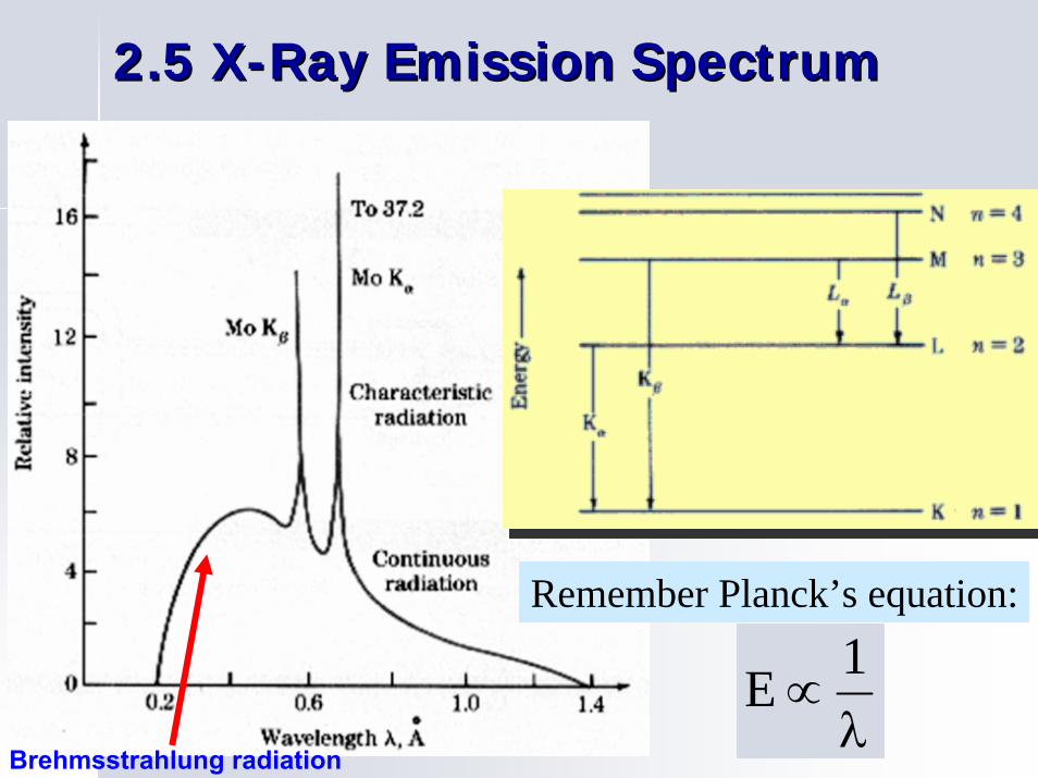
2.5 X2.5 X--Ray Emission SpectrumRay Emission Spectrum
λ∝
1E
Remember Planck’s equation:
Brehmsstrahlung radiation

2.6 The Principle of Generation 2.6 The Principle of Generation BremsstrahlungBremsstrahlung
Bremsstrahlung: a German word meaning "braking radiation" (referring to the deceleration of electrons as the cause of the rad ia t ion) . A lso ca l led genera l or white radiat ion .

2.7 The Principle of Generation the Characteristic2.7 The Principle of Generation the CharacteristicRadiationRadiation

TheThe energyenergy ofof thethe characteristiccharacteristic XX--rayraycan be can be usedused forfor specifyingspecifying a a constituentconstituentelementelement sincesince thethe energyenergy atat thethe XX--rayraypeakpeak positionposition isis specificspecific toto eacheachelementelement..
For instance, if the innermost shell (the K shell) electron of an iron atom isreplaced by an L shell electron, a 6400 eV K-α X-ray is emitted from the sample.

Atoms and ions are in the order of 0.1 nm in size.
As seen in the figure, the portion of the electromagnetic spectrum with a wavelength in this range is x-radiation (compared with 100-nm range for the wavelength of the visible light) X-ray diffraction is capable of characterizing crystalline structure.

d=nλ/2sinθc
x-ray intensity (from detector)
θ
θc
• Incoming X-rays diffract from crystal planes.
• Measurement of:Critical angles, θc,for X-rays provideatomic spacing, d.
2.8 X2.8 X--RAYS TO CONFIRM CRYSTAL STRUCTURERAYS TO CONFIRM CRYSTAL STRUCTURE
reflections must be in phase to detect signal
spacing between planes
d
incoming
X-rays
outgoin
g X-ra
ys
detector
θλ
θextra distance travelled by wave “2”
“1”
“2”
“1”
“2”
θ θ

2.9 Derivation of2.9 Derivation of BraggBragg’’s Laws Law
2 sinnd λ
θ⋅
=⋅
AB = BCABC = 2 BCBC = d sin θ
this path length difference is an
integral number of wavelengths
ABC = n λ = 2 BC = 2 d sin θ
n λ = 2 d sin θ

2.10 X2.10 X--Ray Beam Interaction with the Ray Beam Interaction with the SpecimenSpecimen
ABC is the only difference between both X-ray trajectories
Incidence angle = take-off angle

2.11 Bragg2.11 Bragg’’s Laws Law
In order to get constructive interaction:
θ
θ⋅=λ= sind2nABC
dA
BC
where n is an integer
and d is the interplanar distance: 222 lkh
ad++
=


2.12 Other Conditions for 2.12 Other Conditions for DiffractionDiffraction
BraggBragg’’s law is a s law is a necessary but not sufficientnecessary but not sufficient condition for condition for diffraction.diffraction.
It defines the diffraction condition for primitive unit cells, It defines the diffraction condition for primitive unit cells, that is, that is, those those BravaisBravais lattices with lattice points only at unit cell corners, lattices with lattice points only at unit cell corners, such as SC and simple tetragonal.such as SC and simple tetragonal.
Crystal structures with non primitive unit cells have atoms at Crystal structures with non primitive unit cells have atoms at additional lattice sites located along a unit cell edge, within additional lattice sites located along a unit cell edge, within a unit a unit cell face or in the interior of the unit cell.cell face or in the interior of the unit cell.
The extra scattering centers can cause outThe extra scattering centers can cause out--ofof--phase scattering to phase scattering to occur at certain Bragg angles occur at certain Bragg angles some of the diffraction lines some of the diffraction lines predicted by Braggpredicted by Bragg’’s law does not occur.s law does not occur.

3. 3. FactorsFactors thatthat AffectAffect thethe DiffractedDiffractedIntensityIntensity
StructureStructure FactorFactorPolarizationPolarization FactorFactorLorentzLorentz FactorFactorMultiplicityMultiplicity FactorFactorTemperatureTemperature Factor Factor AbsorptionAbsorption FactorFactor

3.1 Structure Factor3.1 Structure Factor
The structure factor for a particular The structure factor for a particular hklhklreflection is given byreflection is given by::
TheThe intensityintensity ofof a a BraggBragg reflectionreflection isisproportionalproportional toto thethe squaresquare ofof thethestructurestructure factor:factor:
)(2 jjj lwkvhuij
j
lhkl efF ++Σ= π
2hklhklhkl FFFI =∝ ∗

3.13.1--1 1 PrimitivePrimitive CubicCubic CellCell
22
2
)000(2
jhkl
hkl
jhkl
lkhijhkl
fFI
FI
fF
efF
==
=
=
= ⋅+⋅+⋅π
1 atom:
(0,0,0)
= 1

Diffractogram of a Primitive Cubic Cell

3.13.1--2 2 BodyBody CenteredCentered CubicCubic CellCell
[ ]
0
0number odd
4
2numbereven
11
1
2
22
2
)(
)21
21
21(2)00(2
==
==++
==
==++
−=
=
+=
⎥⎦
⎤⎢⎣
⎡+=
++
⋅+⋅+⋅⋅+⋅+⋅
hkl
hkl
jhkl
jhkl
i
i
lkhijhkl
lkhilkohijhkl
FI
Flkh
fFI
fFlkh
ee
efF
eefF
π
π
π
ππ
2 atoms:
(0,0,0)
(1/2,1/2,1/2)

Diffractogram of a Body Centered Cubic
Cell
even:1+1+0=22+0+0=22+1+1=42+2+0=43+1+0=4

3.13.1--3 3 FaceFace CenteredCentered CubicCubic CellCell
4 1 1 1 1 0 1 1- 1- 1
)1( )()()(
)21
210(2)
210
21(2)0
21
21(2)000(2
==
+++=
⎥⎦
⎤⎢⎣
⎡+++=
+++
⋅+⋅+⋅⋅+⋅+⋅⋅+⋅+⋅⋅+⋅+⋅
unmixedmixed
eeefF
eeeefF
lkilhikhijhkl
lkhilkhilkhilkhijhkl
πππ
ππππ

3.13.1--4 4 FaceFace CenteredCentered CubicCubic CellCell
00
,,
16
4odd all even all
,,
2
==
=
=
=
=
IF
mixedlkh
fI
fF
unmixedlkh
hkl
j
jhkl
4 atoms:
(0,0,0)
(1/2,1/2,0)
(1/2,0,1/2)
(0,1/2,1/2)

Diffractogram of a Face Centered Cubic Cell
unmixed:
(1,1,1) - odd
(2,0,0) - even
(2,2,0) - even
(3,1,1) - odd

ExampleExample: : CsClCsCl
Cs+ Cl-
BCC
[ ]
( )
( )2
2
)(
)21
21
21(2)000(2
odd
even
−+
−+
−+
−+
−+
−+
−=
−==++
+=
+==++
+=
⎥⎦
⎤⎢⎣
⎡+=
++
⋅+⋅+⋅⋅+⋅+⋅
ClCs
ClCshkl
ClCs
ClCshkl
lkhiClCshkl
lkhi
Cllkhi
Cshkl
ffI
ffFlkh
ffI
ffFlkh
effF
efefF
π
ππ

CsClCsCl DiffractogramDiffractogram


4. The X4. The X--Ray Diffraction SpectrumRay Diffraction Spectrum
X-Ray diffraction pattern generated by a pure Al sample, under Cu-Kα radiation

4.1 Qualitative Analysis in XRD4.1 Qualitative Analysis in XRD
The diffraction pattern of an unknown The diffraction pattern of an unknown sample is measured and is compared with sample is measured and is compared with already known standards (JCPDS cards) to already known standards (JCPDS cards) to identify it.identify it.

4.2 Power Diffraction File (PDF) Database

4.3 Special Features in PDF Cards

February 6th, 2003 422nd Int’l. Conf. On X-ray Analysis – Durham, 2001
PDF Card
Historical“Card”Format
New PDF-4 Card offeringtabular visualizationand on-the-flycalculations
PDF PDF CardCard –– historicalhistorical cardcard formatformat

Power Diffraction File (PDF) Database

4.4 The 4.4 The HanawaltHanawalt MethodMethod

4.4 The 4.4 The HanawaltHanawalt Method (contMethod (cont’’))

4.4 The 4.4 The HanawaltHanawalt Method (contMethod (cont’’))

4.4 The 4.4 The HanawaltHanawalt Method (contMethod (cont’’))

4.4 The 4.4 The HanawaltHanawaltMethod (contMethod (cont’’))

4.5 Computer Search of the PDF

4.6 XRD: Crystallite Size4.6 XRD: Crystallite Size
The peak width in in XRD pattern is The peak width in in XRD pattern is related to the size of crystallites that related to the size of crystallites that compose the materialcompose the material

4.6 Crystallite Size4.6 Crystallite Size

4.6 Crystallite Size4.6 Crystallite Size

4.6 Crystallite Size4.6 Crystallite Size

4.7 Derivation of 4.7 Derivation of ScherrerScherrer’’ss EquationEquation
Bragg's law is given by, Bragg's law is given by,
n n λλ =2 d sin =2 d sin θθ ……………………. (1). (1)
Multiply both sides by an integer m such that Multiply both sides by an integer m such that mdmd=t, =t, the thickness of the crystal. This leads to, n=1:the thickness of the crystal. This leads to, n=1:
m m λλ =2 m d sin =2 m d sin θθm m λλ =2 t sin =2 t sin θθ ……..………………. (2). (2)
EqnEqn. (2) can also be interpreted as the m . (2) can also be interpreted as the m thth order order reflection from a set of planes with a interplanar reflection from a set of planes with a interplanar distance t. Differentiate both sides of distance t. Differentiate both sides of eqneqn. (2) . (2) remembering m remembering m λλ is a constant. This gives,is a constant. This gives,
0 = 2 0 = 2 ΔΔt sin t sin θθ ++ 2 t 2 t coscos θθ ΔθΔθ …… (3)(3)
Remembering that as Remembering that as Δ θΔ θ can be positive or negative can be positive or negative (we are only interested in absolute values) leads to, (we are only interested in absolute values) leads to,
……………… (4)(4)
Since the smallest increment in t is d, using Since the smallest increment in t is d, using ΔΔ t=d, and substituting t=d, and substituting λλ /2 for /2 for dsindsinθθ (from (from Bragg's law) we get,Bragg's law) we get,
………………..……. (5). (5)
Substituting B for 2 Substituting B for 2 ΔΔθθ, the angular width, , the angular width, we get, we get,
…………....……..……. (6). (6)
which is essentially which is essentially ScherrerScherrer’’ss equation.equation.
A more sophisticated analysis of the A more sophisticated analysis of the problem only adds a problem only adds a prefactorprefactor of 0.9 to the of 0.9 to the right hand side of right hand side of eqneqn. (6) and leads to the . (6) and leads to the correct correct ScherrerScherrer’’ss equation.equation.
)( cos )sin(ttθθ
θΔ
⋅Δ=
)( cos Bt
θλ
=
)( cos B9.0t
θλ⋅
=
)( cos 2t
θθλ
Δ=

)( cos B9.0t
θλ⋅
=
ε - Cobalt particles gold plated(High Coercivity Materials Group 2006)

The The ScherrerScherrer’’ss EquationEquation

The The ScherrerScherrer’’ss EquationEquation

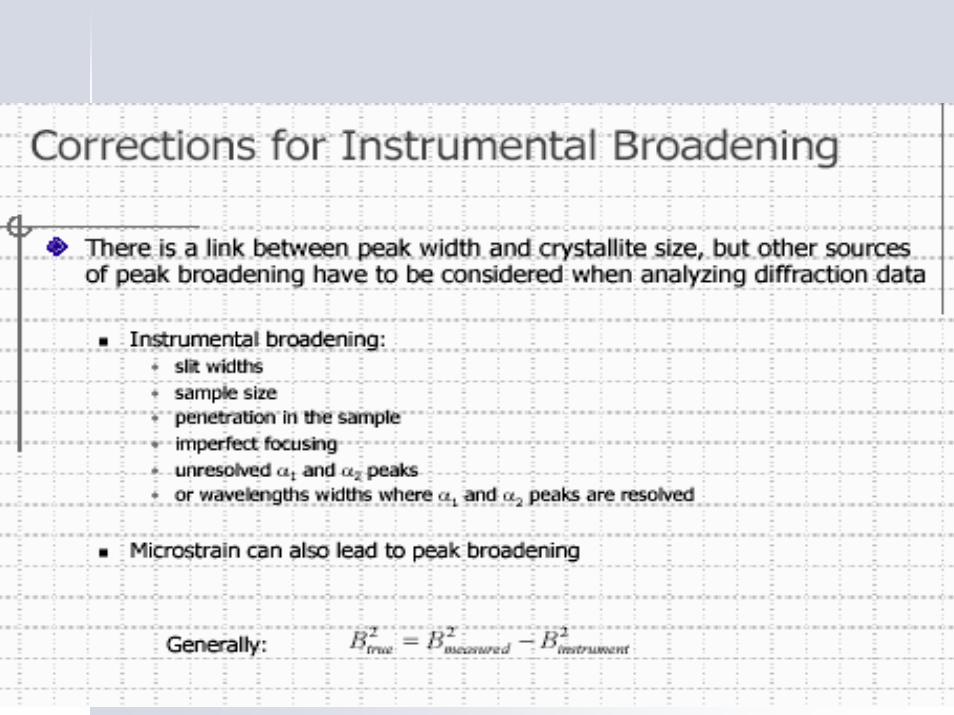
4.8 Peak Broadening4.8 Peak Broadening
•• If crystal size < 0.2 If crystal size < 0.2 μμm, then peak broadening occursm, then peak broadening occurs•• At <50nm, becomes significant.At <50nm, becomes significant.•• Why?Why?BraggBragg’’s law gives the condition for constructive interference.s law gives the condition for constructive interference.•• At slightly higher At slightly higher θθ than the Bragg angle, each plane gives than the Bragg angle, each plane gives
a a ““laglag”” in the diffracted beam.in the diffracted beam.•• For many planes, these end up cancelling out and thus the For many planes, these end up cancelling out and thus the
net diffraction is zero.net diffraction is zero.•• Peak broadness also depend on the presence of lattice Peak broadness also depend on the presence of lattice
imperfections and non uniform distortion of the crystallite.imperfections and non uniform distortion of the crystallite.

4.8 Peak Broadening4.8 Peak BroadeningWe can calculate the average size of the crystals from We can calculate the average size of the crystals from
the broadening:the broadening:
BcosB9.0t
θλ
= Scherrer formula
t is the thickness of the crystal, λ the wavelength, θB the Bragg angle.
B is the line broadening, by reference to a standard, so that 2
S2M
2 BBB −=
where BS is the halfwidth of the standard material in radians. (A normal halfwidth is around 0.1o)

4.8 Peak Broadening4.8 Peak BroadeningHalfwidth: “Full width at half-maximum” - FWHM

4.8 Peak Broadening4.8 Peak BroadeningExample:
Peak at 28.2° 2θ with FWHM of 0.36 ° 2θ
Standard material has FWHM of 0.16 ° 2θ
λ = CuKα = 1.540Å
0.36 ° = 0.36 x π/180 = 0.0063 rad
0.16 ° = 0.16 x π/180 = 0.0028 rad
B = 0.0056 rad
t = 255 Å = 0.0255 μm

15 20 25 30 35 40 45 50 55 60 65 70
(311)
(220)
(111)
ZnS bulk
x=0.05
x=0
x=0.1
x=0.2
Inte
nsity
(Arb
. Uni
ts)
2θ
ZnS:Mn2+ / 0.02M
Nanocrystalline Nanocrystalline MnMn--doped ZnSdoped ZnS

Fig. 2 SEM micrographs (a & b) at different magnifications corresponding to the films deposited from a bath solution with a total concentration of metal ions (Zn + Mn) 0.02 M and a Mn mole fraction, x = 0.1. Very tiny primary particles are observed inside each micronsize particle. Fig. (C) is for [M] = 0.03M showing some cracks.


4.9 XRD: Residual Stress4.9 XRD: Residual Stress
When force is applied on a solid When force is applied on a solid matter with its elastic limit, it is matter with its elastic limit, it is deformed deformed ‘‘dd’’ will change will change XRD XRD peak will be shiftedpeak will be shifted


WilliamsonWilliamson--HallHall’’s analysis:s analysis:It can be used to estimate crystallite size It can be used to estimate crystallite size and average lattice strainand average lattice strain
A method of interpreting particle size broadening and strain A method of interpreting particle size broadening and strain broadening. broadening. ββCosCosθθ vsvs SinSinθθ should be plottedshould be plotted
ββ coscos θθ = 4e (sin = 4e (sin θ)θ) + + λλ//εεβ = β = integral width in radians (crystallite size + integral width in radians (crystallite size +
non uniform distortion)non uniform distortion)θθ = Braggs= Braggs’’ angle of diffracted raysangle of diffracted raysεε = crystallite size= crystallite sizee= mean lattice straine= mean lattice strain

ReferenceReference
O. O. PeralesPerales, PhD. , PhD. Introduction To Characterization of Nanomaterials: XRD and Electron Microscopy Techniques; Power Point Presentation, 1st Semester Introduction to Material Characterization 2006-07 UPRMSiemens D5000: X Ray Siemens D5000: X Ray DiffraktometerDiffraktometer –– Operating ManualOperating ManualWeb site: Hyper PhysicsWeb site: Hyper Physics
