introduction to the x86 microprocessor prof. v. kamakoti digital circuits and vlsi laboratory indian...
TRANSCRIPT
Introduction to The x86 Microprocessor
Prof. V. Kamakoti
Digital Circuits And VLSI Laboratory
Indian Institute of Technology, Madras
Chennai - 600 036.
http://vlsi.cs.iitm.ernet.in

Protected Mode
Memory Segmentation and Privilege Levels
• Definition of a segment
• Segment selectors
• Local Descriptor Tables
• Segment Aliasing, Overlapping
• Privilege protection
• Defining Privilege Levels
• Changing Privilege levels

Organization
Basic Introduction Structured Computer Organization
Memory Management Architectural Support to Operating Systems and users
Process Management Architectural Support to Operating Systems
• Task Switching and Interrupt/Exception Handling Legacy Management
Instruction set compatibility across evolving processor Architectures
Evolution of Instruction Sets – MMX Instructions

Intel Processor operation modes Intel processor runs in five modes of operations
Real Mode Protected Mode Virtual 8086 mode IA 32e – Extended Memory model for 64-bits
• Compatibility mode – execute 32 bit code in 64-bit mode without recompilation. No access to 64-bit address space
• 64-bit mode – 64-bit OS accessing 64-bit address space and 64-bit registers
System Management mode Real mode is equivalent to 8086 mode of operation with some
extensions Protected Mode is what is commonly used Virtual 8086 mode is used to run 8086 compatible programs concurrently with other protected mode programs

Structured Computer Organization
Programming Language level
Assembly Language level
Operating Systems level
Microprogramming level
Digital Logic level
Computer
Architecture
Compilers askfor features from the
Architecture to induce more
sophisticationin the Programming
Languages
Compiled code/ Assembly code
Advanced Addressing modes
Sophisticated Instruction set
Support for Memory Management
and Task ManagementMultiuser OS - Protection,
VirtualMemory, Context Switching
Intel
UnderstandingHow I manage
these demands makes my
biographyinteresting

Memory Management
Multi User Operating Systems Ease of Programming Process Mobility in the Address Space Multiprocess Context switching Protection across Processes
• Intra process protection: Separation of Code, Data and Stack
• Inter process protection
Virtual Memory 4GB address space for every process
Ensured by
Segmentation
Ensured by
Paging
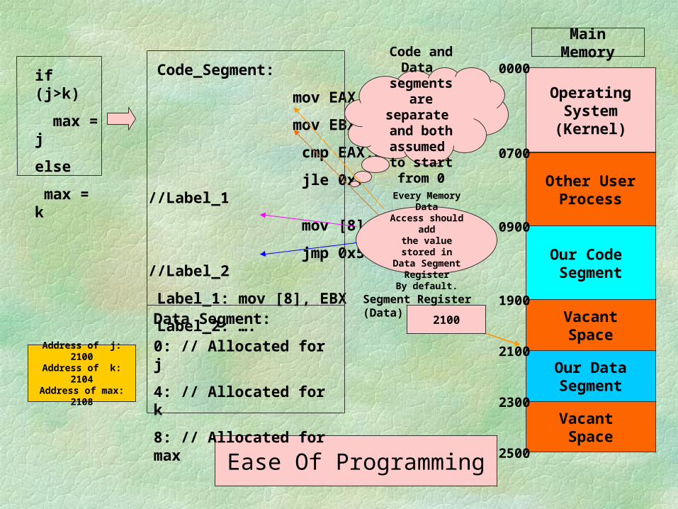
if (j>k)
max = j
else
max = k
Code_Segment:
mov EAX, [0]
mov EBX, [4]
cmp EAX,EBX
jle 0x7 //Label_1
mov [8], EAX
jmp 0x5 //Label_2
Label_1: mov [8], EBX
Label_2: ….
Ease Of Programming
Data Segment:
0: // Allocated for j
4: // Allocated for k
8: // Allocated for max
Code and Data segments are
separate and both assumed
to start from 0
Operating System(Kernel)
Main Memory
Other UserProcess
Our Code Segment
VacantSpace
Our DataSegment
Vacant Space
0000
0700
0900
1900
2100
2300
2500
Address of j: 2100Address of k: 2104
Address of max: 2108
2100
Segment Register (Data)
Every Memory DataAccess should addthe value stored in
Data Segment Register
By default.

if (j>k)
max = j
else
max = k
Code_Segment:
mov EAX, [0]
mov EBX, [4]
cmp EAX,EBX
jle 0x7 //Label_1
mov [8], EAX
jmp 0x5 //Label_2
Label_1: mov [8], EBX
Label_2: ….
Process Mobility
Data Segment:
0: // Allocated for j
4: // Allocated for k
8: // Allocated for max
Operating System(Kernel)
Main Memory
Other UserProcess
Our Code Segment
VacantSpace
Our DataSegment
Vacant Space
0000
0700
0900
1900
2100
2300
2500
Address of j: 2100Address of k: 2104
Address of max: 2108
2100
Segment Register (Data)
A new process needs a
segment of size 260The space is
availablebut not contiguous
Our DataSegment
VacantSpace
2300 New User Process
2160Vacant Space
Address of j: 2300Address of k: 2304
Address of max: 2308

General Purpose Registers

64-bit and above Registers
RAX, RBX, RCX, RDX, RSI, RSP, RDI, RBP – 64 bit General purpose registers sharing space with its corresponding 32-bit registers
R8-R15, additional general purpose registers R8D – R15D (32 bit counter part) R8W – R15W (16 bit counter part)
ST0-ST7, 80 bit floating point MMX0-MMX7, 64-bit multi media XMM0-XMM7, 128-bit registers – used for floating point
and packed integer arithmetic

Segment Registers

Multiple Segments
The segment register can change its values to point to different segments at different times.
X86 architecture provides additional segment registers to access multi data segments at the same time.
DS, ES, FS and GS X86 supports a separate Stack Segment Register (SS) and a Code
segment Register (CS) in addition. By default a segment register is fixed for every instruction, for all the
memory access performed by it. For eg. all data accessed by MOV instruction take DS as the default segment register.
An segment override prefix is attached to an instruction to change the segment register it uses for memory data access.

Multiple Segments
DS
SS
ES
CS
0000
0500
1500
2500
3500
mov [10], eax
- this will move the contents of eax register to memory location 0510
Opcode: 0x89 0x05 0x10
mov [ES:10], eax
-this will move the contents of eax register to memory location 3510
Opcode
0x26 0x89 0x05 0x10
“0x26” is the segment override prefix.

Multiprocess Context switching
Process 1 CS
Process 1 DS
Process 2 CS
Process 2 SS
Process 2 DS
Process 1 SS
CS
DS
SS
Process 1 in Execution
Process 2
in
Execution

Other Registers
EFLAGS – 32 Bit Register
CFPFAFZFSFTFIFDFOFIO
PL
IO
PL
NTRFVM
Bits 1,3,5,15,22-31 are RESERVED.
18: AC, 19:VIF, 20: VIP, 21:ID

Details of the flags
CF – Carry Flag Set by arithmetic instructions that generate a
carry or borrow. Also can be set, inverted and cleared with the STC, CLC or CMC instructions respectively.
PF – Parity Flag Set by most instructions if the least significant
eight bits of the destination operand contain an even number of 1 bits.

Details of the flags
AF – Auxiliary Flag If a carry or borrow from the most significant
nibble of the least significant byte – Aids BCD arithmetic
ZF – Zero Flag Set by most instructions if the result of the
arithmetic operation is zero

Details of the flags
SF – Sign Flag On signed operands, this tells whether the result
is positive or negative
TF – Trace Flag On being set it allows single-step through
programs. Executes exactly one instruction and generates an internal exception 1 (debug fault)

Details of the flags
IF – Interrupt Flag When set, the processor recognizes the external
hardware interrupts on INTR pin. On clearing, anyway has not effect on NMI (external non maskable interrupt) pin or internally generated faults, exceptions, traps etc. This flag can be set and cleared using the STI and CLI instructions respectively
DF – Direction Flag Specifically for string instructions. DF = 1 increments
ESI and EDI, while DF = 0 decrements the same. Set and cleared by STD and CLD instructions

Details of the flags
OF – Overflow Flag Most arithmetic instructions set this flag to
indicate that the result was at least 1 bit too large to fit in the destination
IOPL – Input Output Privilege Level flags For protected mode operations – indicates the
privilege level, 0 to 3, at which your code must be running in order to execute any I/O-related instructions
Details of the flags
NT – Nested Task Flag When set, it indicates that one system task has
invoked another through a CALL instruction as opposed to a JMP. For multitasking this can be manipulated to our advantage
RF – Resume Flag It is related to Debug registers DR6 and DR7.
By setting this, you can selectively mask some exceptions while you are debugging code

Details of the flags VM – Virtual 8086 mode flag
When it is set, the x86 processor is basically converted into a high-speed 8086 processor.
AC (bit 18) Alignment check flag — Set this flag and the AM bit in the CR0 register to
enable alignment checking of memory references; clear the AC flag and/or the
AM bit to disable alignment checking. VIF (bit 19) Virtual interrupt flag — Virtual image of
the IF flag. Used in conjunction with the VIP flag. (To use this flag and the VIP flag the virtual
mode extensions are enabled by setting the VME flag in control register CR4.)

Details of the flags
VIP (bit 20) Virtual interrupt pending flag — Set to indicate that an interrupt is pending;
clear when no interrupt is pending. (Software sets and clears this flag; the
processor only reads it.) Used in conjunction with the VIF flag.
ID (bit 21) Identification flag — The ability of a program to set or clear this flag indicates
support for the CPUID instruction.
Protected Mode Registers
LDTR – Local Descriptor Table Register – 16 bits
GDTR – Global Descriptor Table Register – 48 bits
IDTR – Interrupt Descriptor Table Register – 48 bits
TR – Task register – 16 bits

Other System Registers
Control – CR0, CR2, CR3 (each 32-bits) CR0 is very important
• Bit 0 – PE bit – when set processor in protected mode else real mode
• Bit 3 – TS bit – The processor sets this bit automatically every time it performs a task switch. This can be cleared using a CLTS instruction
• Bit 31 – PG bit – when set paging MMU is enabled else it is disabled

Other System Registers
Control – CR0, CR2, CR3 (each 32-bits) CR2 – Read only register – deposits the last 32-
bit linear address that caused a page-fault CR3 – Stores the physical address of the PDB –
Page Directory Base register. The paging tables are to be 4KB aligned and hence the 12 least significant bits are not stored and ignored
Other System Registers
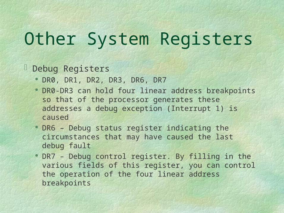
Debug Registers DR0, DR1, DR2, DR3, DR6, DR7 DR0-DR3 can hold four linear address breakpoints so
that of the processor generates these addresses a debug exception (Interrupt 1) is caused
DR6 – Debug status register indicating the circumstances that may have caused the last debug fault
DR7 – Debug control register. By filling in the various fields of this register, you can control the operation of the four linear address breakpoints

Other System Registers
Test Registers – TR6 and TR7 Used to perform confidence checking on the
paging MMU’s Translation Lookaside Buffer (TLB).


Test Your Understanding
There are ------- GPRs in the x86The x86 system in protected mode has
-------- enabled by defaultThree salient features of using
Segmentation

Answers
1. Eight GPRs2. Segmentation3. Three Features
Code Mobility Logically every segment can start with zero Inter and Intra process protection ensuring data
integrity.

Learnt so far
Intel Memory Management fundamentals• Motivation from a Computer Organization standpoint• Intel Register set – General Purpose Registers, Segment
registers and system registers• x86 modes of operations

x86 Memory Management To Learn
Real and protected mode addressing in x86 Virtual Memory and paging Addressing Task switching and Interrupt handling Legacy issues
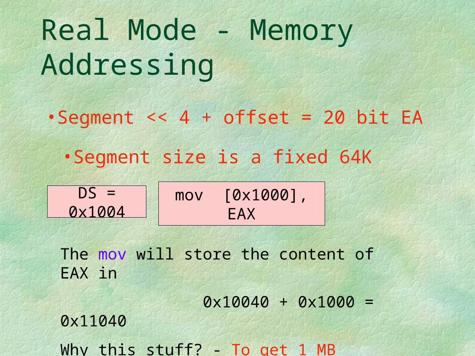
Real Mode - Memory Addressing
•Segment << 4 + offset = 20 bit EA
DS = 0x1004 mov [0x1000], EAX
The mov will store the content of EAX in
0x10040 + 0x1000 = 0x11040
Why this stuff? - To get 1 MB addressing using 16-bit Segment Registers
•Segment size is a fixed 64K
Protected Mode Addressing
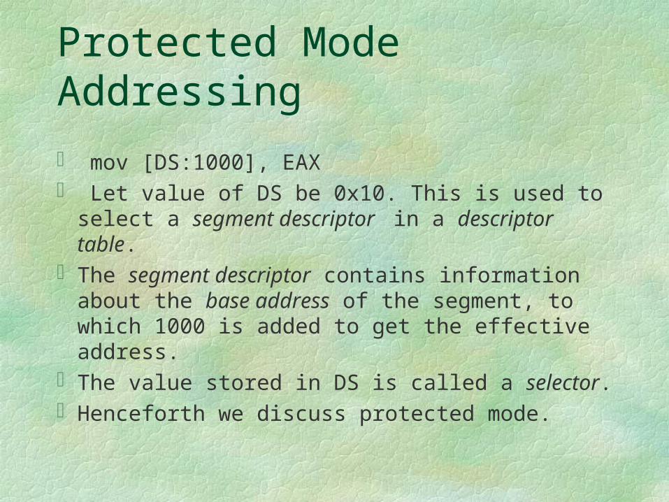
mov [DS:1000], EAX Let value of DS be 0x10. This is used to select a
segment descriptor in a descriptor table.The segment descriptor contains information
about the base address of the segment, to which 1000 is added to get the effective address.
The value stored in DS is called a selector.Henceforth we discuss protected mode.

Protected Mode Addressing
SELECTOR OFFSET
Descriptor Table
Base Address
Linear Address
Logical Address
Segment Descriptor

Intra and Inter process Protection
•A process always executes from Code segment. It should not execute by accessing from adjoining Data or stack area or any other code area too.
•A stack should not overgrow into adjoining segments
Every segment is specified a start address and limit.
Architecture checks if limit is not exceeded.
CS
ES
SS
500
1000
1500
2000
jmp CS:250 //This is finejmp CS:501 //This is a violation as limit is 500mov [ES:498], AX //This is finemov [ES:498], EAX //This is a violation!!!PUSH AX //Let SP be 498, it is finePUSH EAX //Let SP be 498, violationPOP AX //Let SP be 2, it is finePOP EAX //Let SP be 2, Violation!!!

Interprocess Protection
Process 1 CS
Process 1 DS
Process 2 CS
Process 2 SS
Process 2 DS
Process 1 SS
CS
DS
SS
Process 1 should be prevented from loading CS, such that it can access the code of Process 2
Similarly for the DS,SS, ES, FS and GS
Privilege levels: [0-3] assigned to each segment.
0: Highest privilege
3: Lowest privilege

Privilege levels and Protection
Every segment has an associated privilege level and hence any code segment will have an associated privilege level.
The CPL (Current Privilege Level) of a process is the privilege level of the code segment, the code stored in which, it is executing.
A process can access segments that have privilege levels numerically greater than or equal to (less privileged than) its CPL.

Protection Implementation
Every segment is associated with a descriptor stored in a descriptor table.
The privilege level of any segment is stored in its descriptor.
The descriptor table is maintained in memory and the starting location of the table is pointed to by a Descriptor Table Register (DTR).
The segment register stores an offset into this table.

Structure of a Descriptor

Updating Segment registers
Segment registers (DS, ES, SS, GS and FS) are updated by normal MOV instructions.
MOV AX, 0x10 ; MOV DS, AXThe above command is successful if and only if
the descriptor stored at the offset 0x10 in the descriptor table has a privilege level numerically greater than or equal to the CPL.
A process with CPL = 3 cannot load the segment descriptor of CPL <= 2, and hence cannot access the segments.

Updating segment registers
The code segment register is updated by normal jump/call operations.
jmp 0x20:0x1000 This updates the CS by 0x20, provided the descriptor
stored at offset 0x20 has a privilege level numerically greater than or equal to CPL
Other modes of updating CS register Numerically higher to lower Privilege Levels using
CALL gates – useful for system calls. Any privilege level to any other privilege level using
task switch.

Descriptor Tables
There are two descriptor tables Global Descriptor Tables Local Descriptor Tables
The global descriptor table’s base address is stored in GDTR
The local descriptor table’s base address is stored in LDTR
The two privileged instructions LGDT and LLDT loads the GDTR and LDTR.

Structure of a Selector
Index T1
0215
T1 = 0 GDT
= 1 LDT
Since segment descriptors are each 8 bytes, the last three bits of the selector is zero, in which one of them is used for LDT/GDT access.

Two process each of PL = 3 should be allotted segments such that one should not access the segments of other.
GDTR GDT
All descriptors in GDT have
PL = 0,1,2
LDTRLDTR
Per process Per process
If at all each process should access memory, it has to use the descriptors in its LDTR only and it cannot change the LDTR/LDT/GDTR/GDT contents as they would be maintained in a higher privileged memory area.
Did You Note!!
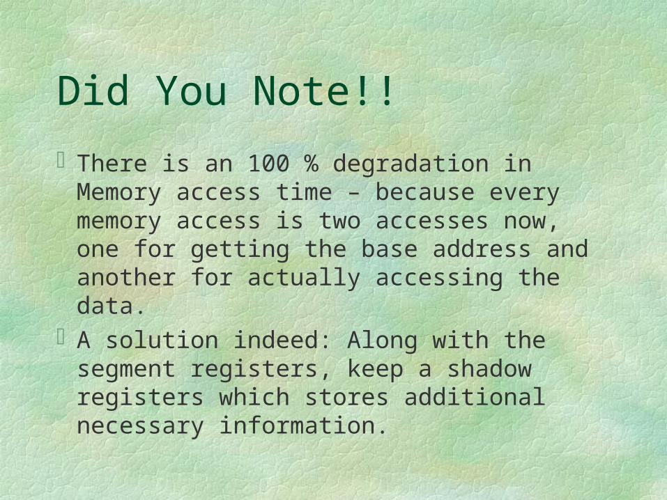
There is an 100 % degradation in Memory access time – because every memory access is two accesses now, one for getting the base address and another for actually accessing the data.
A solution indeed: Along with the segment registers, keep a shadow registers which stores additional necessary information.

Base Address, Limit, DPL.
Segment selector
Visible part Hidden part
CS
SS
DS
ES
FS
GS

Be Careful
0x10 20
120
Descriptor Table
Base Address
Linear Address
Logical Address
Base = 100
Changing Base
Linear address will still be 120
Have to execute
mov DS,0x10 again to get the answer as 220, as this would update the hidden part
Base = 200
add [DS:20],eax

Virtual Memory and Paging
It is always enough if the next instruction to be executed and the data needed to execute the same are available in the memory.
The complete code and data segment need not be available.
Use of paging to realize the stuff!By using segmentation the processor
calculates an 32-bit effective address.

Paging fundamentals
Each page is 4096 bytesPhysical RAM has page frames like photo frames,
which is also 4096 bytes.A page is copied into the page frame, if needed
and removed to accommodate some other page.By this, a 4 GB code can run on a 128MB physical
memoryThis is also called demand paging.

Protected Mode Addressing with paging
DIR TABLE OFFSET
CR3 REG
DIR ENTRY
PG TBL ENTRY
PHYS ADDRSPAGE DIRECTORY PAGE TABLE
PAGE FRAME
121010
4KB entries with 4 bytes per entry
4KB entries with 4 bytes per entry
If 20 bytes are used as a single level paging then page table alone is 4 MB which is inefficient. So two level paging.
Develop the page table on demand
TLB’s used to improve performance
Dirty bit accommodated in each page entry

Protected Mode Addressing - Paging entries
Task Switching
There are different types of descriptors in a Descriptor table.
One of them is a task state segment descriptor. jmp 0x10:<don’t’care> and that 0x10 points to a
TGD, then the current process context is saved and the new process pointed out by the task state segment descriptor is loaded.
A perfect context switch.TSS descriptor only in a GDT.

Task State Segment

Task Switching
Every process has an associated Task State Segment, whose starting point is stored in the Task register.
A task switch happens due to a jmp or call instruction whose segment selector points to a Task state segment descriptor, which in turn points to the base of a new task state segment

Task Switching process

Interrupt Handling
Processor generates interrupts that index into a Interrupt Descriptor Table, whose base is stored in IDTR and loaded using the privileged instruction LIDT.
The descriptors in IDT can be Interrupt gate: ISR handled as a normal call subroutine
– uses the interrupted processor stack to save EIP,CS, (SS, ESP in case of stack switch – new stack got from TSS).
Task gate: ISR handled as a task switch• Needed for stack fault in CPL = 0 and double faults.

Interrupt Handling
Processor handles a total of 255 interrupts0-31 are used by machine or reserved32-255 are user definable0 – Divide error, goes to first descriptor in IDT1 – Debug8 – Double Fault12 – Stack Segment fault13 – General Protection Fault14 – Page Fault

Instruction Set Architecture

Legacy Issues
16-bit code in 32-bit architectureAddress override prefix – 16-bit or 32-bit
addresses in a 32-bit or 16-bit code segmentOperand override prefix
Same opcode for say, add EAX,EBX and add AX,BX
Distinguished by the operand override prefix – 16-bit or 32-bit operands in a 32-bit ot 16-bit code segment
D flag in the code segment descriptor tells the size of the code segment, which is used above.

Effective Address Calculation

Legacy Issues
mod r/m: says if it is a memory or register access
sib: says if it is memory then what addressing is issued for effective address calculation.

Evolving Instruction Sets
The Multimedia Instruction set (MMX) First Major Extension to x86 since 1985 57 new instructions
Audio Video Speech Recognition and synthesis Data communication
Two byte Opcode with 0F prefix Use of Data parallelism at the instruction opcode level to
speedup computation.


x86 Memory Management
To learn Segmentation details Privilege levels and switching

Memory Segmentation
Segment Descriptors 80886 to 80386+
• In 8086, the program is not expected to generate a non-existent memory address. If it does, then the processor shall try to access the same and read bogus data, or crash
• In 80386+ (and above) the segment attributes (base, limit, privilege etc) are programmable and no matter how privileged the code may be, it cannot access an area of memory unless that area is described to it.

Insight into 80386+ segments
Segments are Areas of memory Defined by the programmer Used for different purposes, such as code, data and
stack
Segments are not All the same size Necessarily paragraph aligned Limited to 64KB

Segment Descriptors
Describes a segment using 64-bits (0-63)Must be created for every segmentIs created by the programmerDetermines a segment’s base address (32-
bits) (Bits 16-39, 56-63)Determines a segment’s size (20-bits) (Bits
0-15, 48-51)

Segment Descriptors (Cont’d)
Defines whether a segment is a system segment (=0) or non-system (=1) (code, data or stack) segment (System bit) (Bit 44)
Determines a segment’s use/type (3-bits) (Bits 41-43) after the above classification
Determines a segment’s privilege level (2 bits) (Bits 45-46) – DPL (Descriptor Privilege Level) Bits

Segment Descriptor (Cont’d)
Accessed (A)-bit: Bit 40, automatically set and not cleared by the processor when a memory reference is made to the segment described by this descriptor.
Present (P)-bit: Bit 47, indicates whether the segment described by this descriptor is currently available in physical memory or not.
Bits 40-47 of the descriptor is called the Access Right Byte of the descriptor.
User (U)-bit and X bit: Bit 52 (U-bit) not used and Bit 53 (X-bit) reserved by Intel

Segment Descriptor (Cont’d)
Default size (D)-bit: Bit 54, when this bit is cleared, operands contained within this segment are assumed to be 16 bits in size. When it is set, operands are assumed to be 32-bits.
Granularity (G)-bit: Bit 55, when this bit is cleared the 20-bit limit field is assumed to be measured in units of 1byte. If it is set, the limit field is in units of 4096 bytes.

Types of non-system segment descriptors
System bit S = 1 000 – Data, Read only 001 – Data, Read/Write 010 – expand down, Read only 011 – expand down, Read/Write 100 – Code, Execute only 101 – Code, Execute/Read 110 – Conforming Code, Execute only 111 - Conforming Code, Execute/Read

D-bit for different descriptors
Code segment D = 0 then 16-bit 80286 code D = 1 then 32-bit 80386+ code
Stack Segment D = 0 then stack operations are 16-bit wide, SP is used
as a stack pointer, maximum stack size is FFFF (64 KB)
D = 1 then stack operations are 32-bit wide, ESP is used as a stack pointer, maximum stack size is FFFFFFFF (4 GB)

G-bit for descriptors
G = 0 then a limit field in descriptor of value p indicates we can access p-1 bytes from base
G = 1 then a limit field in descriptor of value p indicates we can access (p * 4096) - 1 bytes from base

Stack/expand down segments
All offsets must be greater than limit.In stack descriptor, D and G bits are to be
the same, else contradiction.
Base
FFFF
Addressable area
Base
FFFFAddressable area
Stack/expand-down
Non-stack
LimitLimit

Descriptor Tables
Descriptors are stored in three tables: Global descriptor table (GDT)
• Maintains a list of most segments• May contain special “system” descriptors• The first descriptor is a null descriptor
Interrupt descriptor table (IDT)• Maintains a list of interrupt service routines
Local descriptor table (LDT)• Is optional• Extends range of GDT• Is allocated to each task when multitasking is enabled• The first descriptor is a null descriptor

Locations of the tables
In MemoryPointed out by GDTR, LDTR and IDTR for the
GDT, LDT and IDT respectively.The GDTR and IDTR are 48-bits in length, the
first 16-bits (least significant) storing the size (limit) of the table and the remaining storing a 32-bit address pointing to the base of the tables
Limit = (no. of descriptors * 8) - 1LLDT stores a 16-bit selector pointing to an entry
in the GDT.

Segment Selectors
Out of several segments described in your GDT and LDT, which of the segment(s) that are currently being used are pointed to by the 16-bit CS,DS,ES,FS,GS and SS registers.
Each store a selector Since descriptors are at 8-byte boundaries, the 16-bit
selectors store the first most significant 13 bits to point to the corresponding descriptor.
The bit 2 is the T1 bit, which when 0 (1) implies the selector is pointing to a descriptor in GDT (LDT).
The bits (0-1) – are the Request Privilege Level (RPL) bits used for privilege assignments.

Loading Segment Selectors into segment registers
Whenever segment registers are loaded, the following rules are checked by the processor and if violated an exception is raised thus giving high degree of memory protection
Rule 1: Index field of the selector within limits of the GDT/LDT to be accessed – else raise a General Protection Fault exception.
Loading Segment Selectors into segment registers
Rule 2: Loading a selector into DS,ES,FS or GS that points to a non-readable segment results in an exception
Rule 3: For loading into SS, the segment pointed to should be readable and writable
Rule 4: For loading into CS, the segment should be executable type
Rule 5: Privilege level check rules to be described later

Loading segment selectors
All segment registers except CS may be loaded using MOV, LDS, LES, LFS, LGS and LSS.
The CS is loaded using a JMP or a CALL instruction – discussed later

Local Descriptor Table
Is defined by a system descriptor (S=0) in GDT which is pointed to by the LDT.
Limit
15-0
Base Address
23-0
0000010PLimit
19-16
0000Base
Address
31-24
The 64-bit descriptor in GDT

Privilege levels
The need is to prevent Users from interfering with one another Users from examining secure data Program bugs from damaging other programs Program bugs from damaging data Malicious attempts to compromise system
integrity Accidental damage to data

Privilege Protection
Continuous checking by the processor on whether the application is privileged enough to
Type 1: Execute certain instructions Type 2: Reference data other than its own Type 3: Transfer control to code other than its own
To manage this every segment has a privilege level called the DPL (Descriptor Privilege Level) Bits 45,46

Descriptor Privilege Level
Privilege levels apply to entire segmentsThe privilege level is defined in the
segment descriptorThe privilege level of the code segment
determines the Current Privilege Level (CPL)

Type 1: Privilege Checking
Privileged Instructions1. Segmentation and Protection Based (HLT, CLTS,
LGDT, LIDT, LLDT, LTR, moving data to Control, Debug and Test registers)
2. Interrupt flag based (CLI, STI, IN, INS, OUT, OUTS)
3. Peripheral IO based First two types of privileged instructions can be
executed only when CPL = 0, that is, these instructions can be in code segment with DPL = 0.

I/O instructions
The I/O based privileged instructions are executed only if CPL <= IOPL in EFLAGS register.
To add to the security the POPF/POPFD instructions which load values into the EFLAGS shall not touch the IOPL bit or IF bit if CPL > 0.

Type 2: Privilege Checking
Reference data other than its own Load a selector into a DS, ES, FS and GS iff
max(RPL,CPL) <= DPL RPL may weaken your privilege level Decreasing RPL will not strengthen your privilege level
– Why? Why to decrease RPL – will discuss later
Load a descriptor into a stack iff DPL = CPL All these are in addition to the rules for loading segment
selector, that were stated in Slides 87 and 88.

Type 3: Privilege Checking
Transfer control to code other than its own. Essentially load a new selector into CS register
jmp across code segments with same DPL jmp <selector>:<offset of instruction from start
of the new segment> call <selector>:<offset of instruction from start
of the new segment>

Type 3: Privilege Checking
The above jmp, call and ret may be used To move between code segments provided
the destination segment is A code segment (executable permission) Defined with the same privilege level Marked present

Changing Privilege levels
Control transfer from a code of some PL to another code with some other different PL.
Using conforming code segments or a special segment descriptor called call gates.
Conforming code segments confirms with the privilege level of the calling code. So if a control transfer happens from segment S to a confirming segment T, the privilege of T would be the privilege of S.

Conforming Code Segment
The DPL of conforming code segment descriptor <= CPL of invoking code.
Therefore, CPL = 2 can invoke DPL = 1.CPL = 2 cannot invoke code with DPL = 3.Why?
If not, you JMP back or RET to the source code segment after executing the conforming code segment. This should permit return from a numerically low privilege code to a numerically high privilege code, without check.

CALL GATE descriptor
Is defined by a system descriptor (S=0) in GDT which is used by the JMP or CALL.
Destination Offset
15-0
Destination Selector (16 bits)
WC00001100P, DPLDestination offset
31-16
The 64-bit descriptor in GDT
•Not only the selector for the target code segment, but also the offset in the code segment from which you should start executing is specified. The source code segment can only use it like a black-box

Calling Higher privileged code
SEGCALL OFFSETSEGCALL OFFSET
Correct Incorrect
Gate – Sel + offset
Code Desc
Code Seg Code Seg
Code Desc

Call Gates
Are defined like segment descriptorsOccupy a slot in the descriptor tablesProvide the only means to alter the current
privilege levelDefine entry points to other privilege levelsMust be invoked using a CALL Instruction

Call Gate accessibility
Target DPL <= Max (RPL, CPL) <= Gate DPL
For eg. CPL = 2 and the target PL = 0, you should use a Gate with PL = 2 or 3

Privilege levels and Stacks
The stack PL = CPL alwaysWhen changing the CPL, the processor
automatically changes the stack!!!How – using the Task State Segment (TSS)The base of the TSS is stored in a Task register
(TR) which is updated by the privileged instruction LTR
The TSS associates a stack for each code for each of the privilege levels 0, 1 and 2

Task Switching process