introduction to the ventilation experiment (ve) and task a b. garitte and a. gens (cimne – upc)...
Post on 20-Dec-2015
216 views
TRANSCRIPT
Introduction to the Ventilation Experiment (VE) and Task A
B. Garitte and A. Gens (CIMNE – UPC)
Dept. of Geotechnical Engineering and GeosciencesTECHNICAL UNIVERSITY OF CATALONIA (UPC)
3rd DECOVALEX 2011 workshop, 21th of April 2009, , Gyeongju, Korea


The Ventilation Experiment (VE)

I greet you all and I invite you to have a
meeting in Mont Terri and to visit the Mont Terri facility.

Task A
Step 0 (reminder)
Opalinus Clay and the Mont Terri site
Ventilation Test: description and observations
Summary
Index
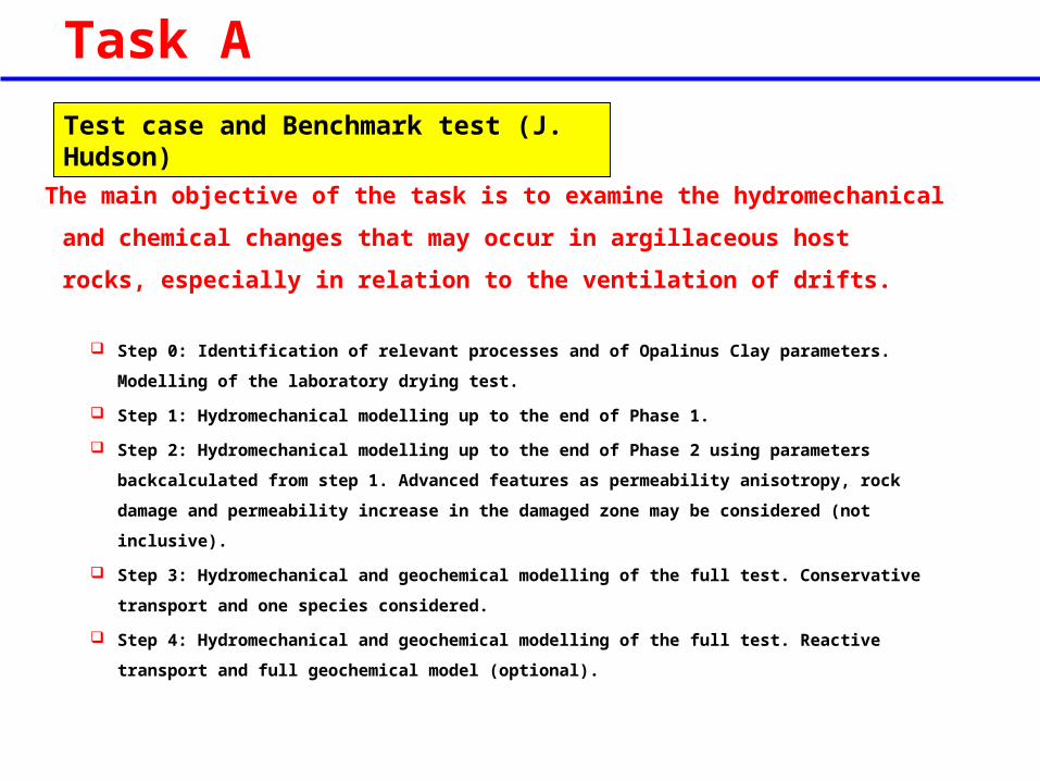
Task A
Test case and Benchmark test (J. Hudson)
The main objective of the task is to examine the hydromechanical and
chemical changes that may occur in argillaceous host rocks, especially in
relation to the ventilation of drifts.
Step 0: Identification of relevant processes and of Opalinus Clay parameters. Modelling of the
laboratory drying test.
Step 1: Hydromechanical modelling up to the end of Phase 1.
Step 2: Hydromechanical modelling up to the end of Phase 2 using parameters backcalculated
from step 1. Advanced features as permeability anisotropy, rock damage and permeability
increase in the damaged zone may be considered (not inclusive).
Step 3: Hydromechanical and geochemical modelling of the full test. Conservative transport
and one species considered.
Step 4: Hydromechanical and geochemical modelling of the full test. Reactive transport and
full geochemical model (optional).

Task A
Step 0: Identification of relevant processes and of Opalinus Clay parameters. Modelling of the
laboratory drying test.
Step 1: Hydromechanical modelling up to the end of Phase 1.
Step 2: Hydromechanical modelling up to the end of Phase 2 using parameters backcalculated
from step 1. Advanced features as permeability anisotropy, rock damage and permeability
increase in the damaged zone may be considered (not inclusive).
Step 3: Hydromechanical and geochemical modelling of the full test. Conservative transport
and one species considered.
Step 4: Hydromechanical and geochemical modelling of the full test. Reactive transport and
full geochemical model (optional).
Apr
il 20
08
Oct
ober
200
8
Apr
il 20
09
Apr
il 20
10
Apr
il 20
11
Sep
tem
ber
2011
Project Months 1 2 3 4 5 6 7 8 9 10 11 12 13 14 15 16 17 18 19 20 21 22 23 24 25 26 27 28 29 30 31 32 33 34 35 36 37 38 39 40 41 42Step 0Step 1Step 2Step 3Step 4Final report

Step 0 (reminder)
Apr
il 20
08
Oct
ober
200
8
Apr
il 20
09
Apr
il 20
10
Apr
il 20
11
Sep
tem
ber
2011
Project Months 1 2 3 4 5 6 7 8 9 10 11 12 13 14 15 16 17 18 19 20 21 22 23 24 25 26 27 28 29 30 31 32 33 34 35 36 37 38 39 40 41 42Step 0Step 1Step 2Step 3Step 4Final report
10cm
28cm
1D
No flux
Evaporation is the process by which molecules in a liquid state (e.g. water) spontaneously become gaseous (e.g. water vapour)
wg v
0wv0g
p 100 100
pRH
Relative Humidity is a measurement of the amount of water vapour that exists in a gaseous mixture of air and water
Drying Test

Step 0 (reminder)
Apr
il 20
08
Oct
ober
200
8
Apr
il 20
09
Apr
il 20
10
Apr
il 20
11
Sep
tem
ber
2011
Project Months 1 2 3 4 5 6 7 8 9 10 11 12 13 14 15 16 17 18 19 20 21 22 23 24 25 26 27 28 29 30 31 32 33 34 35 36 37 38 39 40 41 42Step 0Step 1Step 2Step 3Step 4Final report
Rel
ativ
e h
um
idit
y [%
]
20%
50%
142 days00.02
0.04
0.06
0.08
0.1
0.12
0.14
0.16
0.18
0.2
0 50 100 150Time [days]
Wat
er l
oss
[kg
]
CEA JAEA Quintessa UoE CAS Sample A Sample B Sample C
CAS CEA JAEA Quintessa UoE
Advective liquid water transport
Non advective vapour diffusion
Internal report TT conference
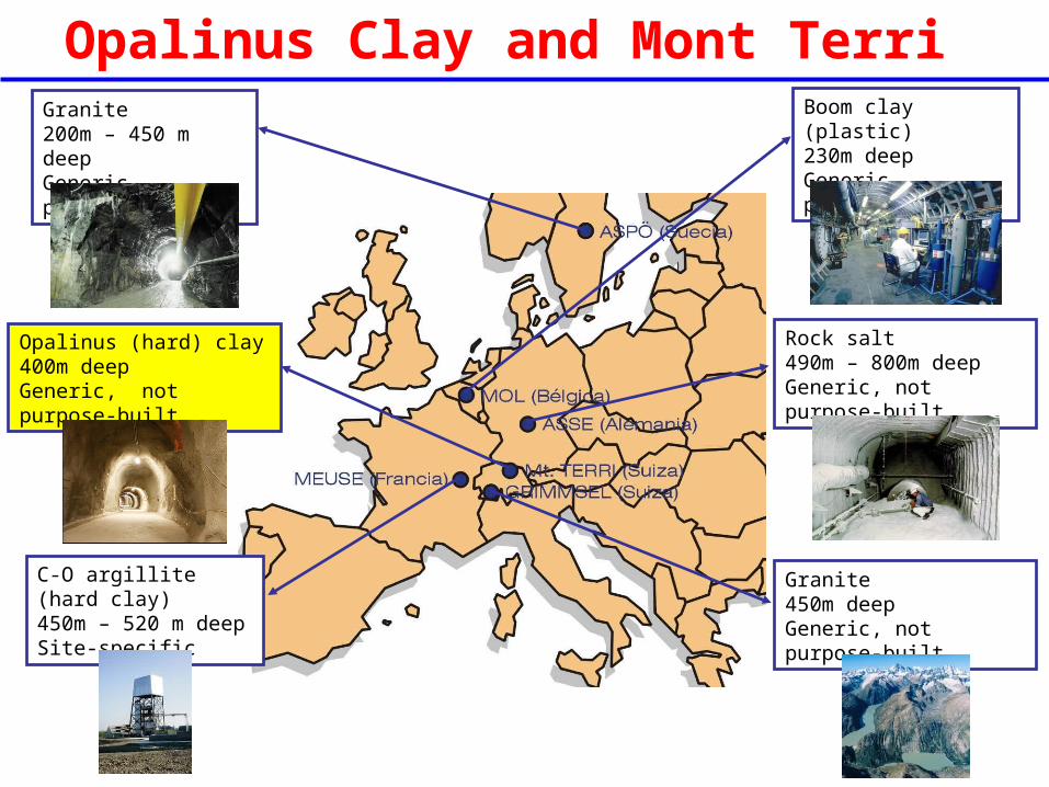
Granite200m – 450 m deepGeneric, purpose-built
Opalinus (hard) clay400m deepGeneric, not purpose-built
C-O argillite (hard clay)450m – 520 m deep Site-specific
Boom clay (plastic)230m deepGeneric, purpose-built
Rock salt490m – 800m deepGeneric, not purpose-built
Granite450m deepGeneric, not purpose-built
Opalinus Clay and Mont Terri

Mont Terri Project
• Located in Northern Switzerland
• Opalinus clay (shale)
• 400 m deep
• Operating since 1995
• Generic, not purpose - built
1: Mont Terri rock laboratory, 400 m beneath the hill2: Southern entrance of the motorway tunnelSource: Mont Terri website
Opalinus Clay and Mont Terri

Opalinus Clay and Mont Terri

• Overconsolidated clay
• Low porosity (±15%)
• Water content (±6%)
• Density (2.45 g/cm3)
• Low permeability (±10-13m/s)
• Variation of stiffness (2 to 10 GPa)
• UCS (10 to 20 MPa)
• Anisotropic material Temperature Mechanical (Strength and
stiffness) Hydraulic (?: selfhealing)
Stiff layered Mesozoic clay of marine origin
Opalinus Clay and Mont Terri

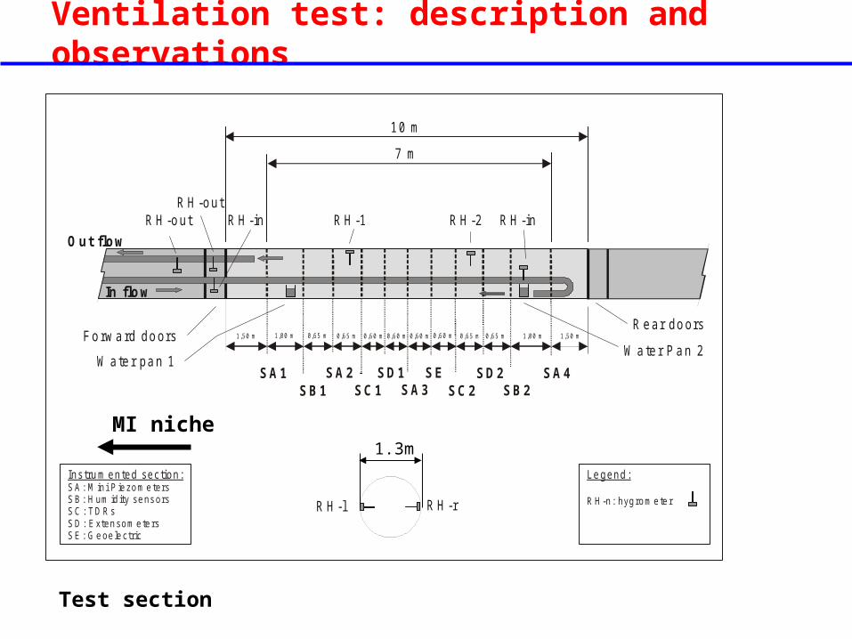
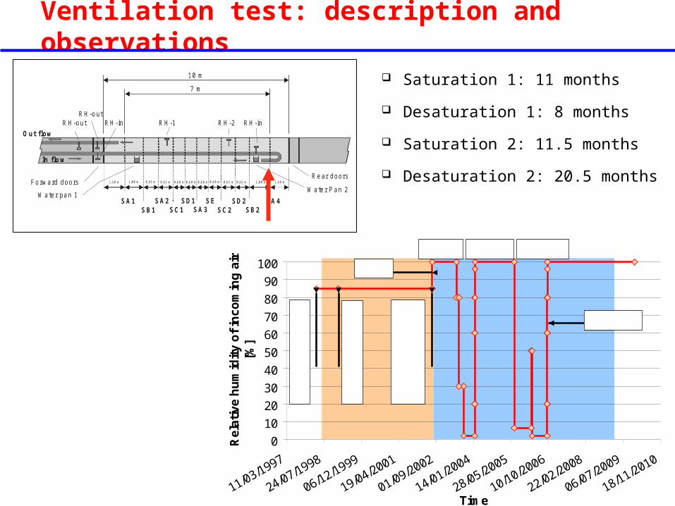
Ventilation test: description and observations
Location of the ventilation test
Raise bored horizontal microtunnel

Ventilation test: description and observations
30 m
Mai
n fa
ult
N
DI n icheHE
BFniche
SH GNniche
EPFLniche
FMCniche
MIniche
O Pniche
PPniche
PPniche
Motorway tunnel
Security gallery
SC ALE
0 2 0m 4 0m 6 0m
MicrotunnelEB
VE
New gallery
Location of the ventilation test
Ventilation test: description and observations
Test section
Section SA3
In flow
RH-out
Water pan 1SA1
SB1 SC1SA2 SD1 SE
SC2 SB2SD2 SA4
SA3
Rear doors
Out flow
RH-outRH-in RH-1 RH-2
Water Pan 2
RH-in
Instru m ented section:SA : M in i P ie zo m e tersSB : H um id ity se ns orsSC : T D RsSD : Exten so m e te rsSE : G e oe le ctric
Forward doors
Le gend :
R H-n : hyg ro m e te rRH-rRH-l
10 m
7 m
1,50 m
1,00 m
0,65 m
0,65 m
0,60 m
0,60 m
0,60 m
0,60 m
1,00 m
0,65 m
0,65 m
1,50 m
MI niche1.3m
Ventilation test: description and observations
Section SA3
In flow
RH-out
Water pan 1SA1
SB1 SC1SA2 SD1 SE
SC2 SB2SD2 SA4
SA3
Rear doors
Out flow
RH-outRH-in RH-1 RH-2
Water Pan 2
RH-in
Instru m ented section:SA : M in i P ie zo m e tersSB : H um id ity se ns orsSC : T D RsSD : Exten so m e te rsSE : G e oe le ctric
Forward doors
Le gend :
R H-n : hyg ro m e te rRH-rRH-l
10 m
7 m
1,50 m
1,00 m
0,65 m
0,65 m
0,60 m
0,60 m
0,60 m
0,60 m
1,00 m
0,65 m
0,65 m
1,50 m
Saturation 1: 11 months
Desaturation 1: 8 months
Saturation 2: 11.5 months
Desaturation 2: 20.5 months
0
10
20
30
40
50
60
70
80
90
100
11/03/1997
24/07/1998
06/12/1999
19/04/2001
01/09/2002
14/01/2004
28/05/2005
10/10/2006
22/02/2008
06/07/2009
18/11/2010
Time
Re
lati
ve h
um
idit
y o
f in
co
min
g a
ir
[%]
9/4
/98:
Exc
. NG
1/2
/99:
Exc
. MT
8/7
/02:
Sea
ling
ve
ntil
ate
d s
ect
ion
24/9/06
8/7/02
28/5/03 29/1/04 11/7/05

Saturation 1: 11 months
Desaturation 1: 8 months
Saturation 2: 11.5 months
Desaturation 2: 20.5 months
Ventilation test: description and observations
Section SA3
In flow
RH-out
Water pan 1SA1
SB1 SC1SA2 SD1 SE
SC2 SB2SD2 SA4
SA3
Rear doors
Out flow
RH-outRH-in RH-1 RH-2
Water Pan 2
RH-in
Instru m ented section:SA : M in i P ie zo m e tersSB : H um id ity se ns orsSC : T D RsSD : Exten so m e te rsSE : G e oe le ctric
Forward doors
Le gend :
R H-n : hyg ro m e te rRH-rRH-l
10 m
7 m
1,50 m
1,00 m
0,65 m
0,65 m
0,60 m
0,60 m
0,60 m
0,60 m
1,00 m
0,65 m
0,65 m
1,50 m
Phase 0
Phase 1
9/4/98 – 8/7/02
8/7/02 – 29/1/04
0
10
20
30
40
50
60
70
80
90
100
11/03/1997
24/07/1998
06/12/1999
19/04/2001
01/09/2002
14/01/2004
28/05/2005
10/10/2006
22/02/2008
06/07/2009
18/11/2010
Time
Re
lati
ve h
um
idit
y o
f in
co
min
g a
ir
[%]
9/4
/98:
Exc
. NG
1/2
/99:
Exc
. MT
8/7
/02:
Sea
ling
ve
ntil
ate
d s
ect
ion
24/9/06
8/7/02
28/5/03 29/1/04 11/7/05

Ventilation test: description and observations
Section SA3
In flow
RH-out
Water pan 1SA1
SB1 SC1SA2 SD1 SE
SC2 SB2SD2 SA4
SA3
Rear doors
Out flow
RH-outRH-in RH-1 RH-2
Water Pan 2
RH-in
Instru m ented section:SA : M in i P ie zo m e tersSB : H um id ity se ns orsSC : T D RsSD : Exten so m e te rsSE : G e oe le ctric
Forward doors
Le gend :
R H-n : hyg ro m e te rRH-rRH-l
10 m
7 m
1,50 m
1,00 m
0,65 m
0,65 m
0,60 m
0,60 m
0,60 m
0,60 m
1,00 m
0,65 m
0,65 m
1,50 m
RH measurements along the
test section
0102030405060708090
100
18-0
7-02
03-0
2-03
22-0
8-03
09-0
3-04
25-0
9-04
13-0
4-05
30-1
0-05
18-0
5-06
04-1
2-06
RH
[%
]

Ventilation test: description and observations
RH measurements along the
test section
0102030405060708090
100
18-0
7-02
03-0
2-03
22-0
8-03
09-0
3-04
25-0
9-04
13-0
4-05
30-1
0-05
18-0
5-06
04-1
2-06
RH
[%
] RH-HyV-In
RH-HyGrUp
TS-RH2
RH-HyCnt-R
RH-HyCnt-L
TS-RH1
RH-HyGR-Dn
RH-HyV-Out

Ventilation test: description and observations
Section SA3
In flow
RH-out
Water pan 1SA1
SB1 SC1SA2 SD1 SE
SC2 SB2SD2 SA4
SA3
Rear doors
Out flow
RH-outRH-in RH-1 RH-2
Water Pan 2
RH-in
Instru m ented section:SA : M in i P ie zo m e tersSB : H um id ity se ns orsSC : T D RsSD : Exten so m e te rsSE : G e oe le ctric
Forward doors
Le gend :
R H-n : hyg ro m e te rRH-rRH-l
10 m
7 m
1,50 m
1,00 m
0,65 m
0,65 m
0,60 m
0,60 m
0,60 m
0,60 m
1,00 m
0,65 m
0,65 m
1,50 m
RH measurements in the
“skin layer”
0102030405060708090
100
18-0
7-02
03-0
2-03
22-0
8-03
09-0
3-04
25-0
9-04
13-0
4-05
30-1
0-05
18-0
5-06
04-1
2-06
RH
[%
]

Ventilation test: description and observations
Section SA3
In flow
RH-out
Water pan 1SA1
SB1 SC1SA2 SD1 SE
SC2 SB2SD2 SA4
SA3
Rear doors
Out flow
RH-outRH-in RH-1 RH-2
Water Pan 2
RH-in
Instru m ented section:SA : M in i P ie zo m e tersSB : H um id ity se ns orsSC : T D RsSD : Exten so m e te rsSE : G e oe le ctric
Forward doors
Le gend :
R H-n : hyg ro m e te rRH-rRH-l
10 m
7 m
1,50 m
1,00 m
0,65 m
0,65 m
0,60 m
0,60 m
0,60 m
0,60 m
1,00 m
0,65 m
0,65 m
1,50 m
-6000
-5000
-4000
-3000
-2000
-1000
0
18/0
7/02
03/0
2/03
22/0
8/03
09/0
3/04
25/0
9/04
13/0
4/05
30/1
0/05
18/0
5/06
04/1
2/06
Time [days from VE start]
Wa
ter
lost
in e
ach
pan
[g
ram
s]
0
10
20
30
40
50
60
70
80
90
100WaterPan-1WaterPan-2
78.5cm2/pan
Water pans

Ventilation test: description and observations
Section SA3
In flow
RH-out
Water pan 1SA1
SB1 SC1SA2 SD1 SE
SC2 SB2SD2 SA4
SA3
Rear doors
Out flow
RH-outRH-in RH-1 RH-2
Water Pan 2
RH-in
Instru m ented section:SA : M in i P ie zo m e tersSB : H um id ity se ns orsSC : T D RsSD : Exten so m e te rsSE : G e oe le ctric
Forward doors
Le gend :
R H-n : hyg ro m e te rRH-rRH-l
10 m
7 m
1,50 m
1,00 m
0,65 m
0,65 m
0,60 m
0,60 m
0,60 m
0,60 m
1,00 m
0,65 m
0,65 m
1,50 m
Mass water balance from
RH-in and RH-out
(First desaturation phase)
0
100w w v wg g g
RH p M
R T
/ww ggq hq kg
10 cm ring
0
100
200
300
400
500
600
28/0
6/03
06/1
0/03
14/0
1/04
23/0
4/04
01/0
8/04
09/1
1/04
17/0
2/05
28/0
5/05
Ext
ract
ed w
ater
[kg
]
0102030405060708090100
RH
[%]
Measured water flux; calculated using qgout =qgin
Measured water flux; calculated using qgout
Wat
er c
omin
g ou
t fr
om t
he s
ectio
n

Ventilation test: description and observations
1
3
5
7
9
0.0 0.5 1.0 1.5 2.0
Distance from bh mouth [m]
wa
ter
co
nte
nt
[%]
BVE_104: Water content [%] (Fernandez ??)
BVE_108: Water content [%] (Fernandez ??)
0.0
0.5
1.0
1.5
2.0
2.5
0.0 0.2 0.4 0.6 0.8 1.0
Distance from bh mouth [m]
Co
nc
en
tra
tio
n
[mo
l/l]
Vertical borehole (Traber, 2004)
Horizontal borehole (Traber, 2004)
Drilling campaigns
0
10
20
30
40
50
60
70
80
90
100
19/04/2001
01/09/2002
14/01/2004
28/05/2005
10/10/2006
22/02/2008
06/07/2009Re
lati
ve
hu
mid
ity
of
inc
om
ing
air
[%
] 5/7/02 26/1/04 1/5/05 4/10/06

50556065707580859095
100
18-0
7-02
03-0
2-03
22-0
8-03
09-0
3-04
25-0
9-04
13-0
4-05
30-1
0-05
18-0
5-06
04-1
2-06
RH
[%
]
HC-SB1/Sur (0.67m)HC-B71 (0.9 m)
HC-B64 (1 m)
HC-B75 (1.15 m)
HC-B66 (1.4 m)
HC-B69 (1.65 m)
HC-B73 (1.9 m)
HC-B77 (2.15 m)
Section B1
Ventilation test: description and observations
RH evolution
16 sensors
Ventilation test: description and observations
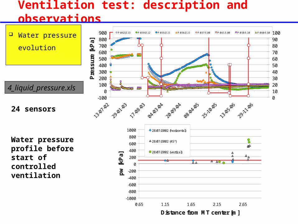
Water pressure
evolution
-1000
100200300400500600700800900
13-0
7-02
29-0
1-03
17-0
8-03
04-0
3-04
20-0
9-04
08-0
4-05
25-1
0-05
13-0
5-06
29-1
1-06
Pre
ssu
re [
kPa]
0102030405060708090100P-B62/2.13 P-B59/2.12 P-B55/2.11 P-B56/2.11 P-B57/1.80 P-B61/1.80 P-B58/1.10 P-B60/1.50
Sec
tio
n A
2
-1000
-800
-600
-400
-200
0
200
400
600
800
1000
0.65 1.15 1.65 2.15 2.65
Distance from MT center [m]
pw
[kP
a]
28/07/2002 (horizontal)
28/07/2002 (45º)
28/07/2002 (vertical)
4_liquid_pressure.xls
24 sensors
Water pressure profile before start of controlled ventilation

Ventilation test: description and observations
-3.5-3
-2.5-2
-1.5-1
-0.50
0.51
1.52
18-0
7-02
03-0
2-03
22-0
8-03
09-0
3-04
25-0
9-04
13-0
4-05
30-1
0-05
18-0
5-06
04-1
2-06
Re
lati
ve d
isp
lace
me
nt
[mm
]0
10
20
30
40
50
60
70
80
90
100
RH
[%
]
46 (vert) 47 (hor) 48 (vert) 49 (hor)
Compression
Expansion
Relative
displacements
8 extensometers
BVE-49
BVE-48
BVE-46
BVE-47
-3
-2
-1
0
1
2
3
-3 -2 -1 0 1 2 3
Section D1
MT
0.5m
1m
1m
0.05%
-0.15%

Step 1: modelling
Section SA3
In flow
RH-out
Water pan 1SA1
SB1 SC1SA2 SD1 SE
SC2 SB2SD2 SA4
SA3
Rear doors
Out flow
RH-outRH-in RH-1 RH-2
Water Pan 2
RH-in
Instru m ented section:SA : M in i P ie zo m e tersSB : H um id ity se ns orsSC : T D RsSD : Exten so m e te rsSE : G e oe le ctric
Forward doors
Le gend :
R H-n : hyg ro m e te rRH-rRH-l
10 m
7 m
1,50 m
1,00 m
0,65 m
0,65 m
0,60 m
0,60 m
0,60 m
0,60 m
1,00 m
0,65 m
0,65 m
1,50 m
Plane strain
0-flow on all borders,
excepted on top
Isothermal (T=15º)
130m
130m 1.85MPa
1.21MPa
2.49MPa
4.9MPa
3.2MPa
6.6MPa
σ =3.2MPa, pw =1.21MPa
pw σ
Isotropic conditions

Step 1: case specifications
Section SA3
In flow
RH-out
Water pan 1SA1
SB1 SC1SA2 SD1 SE
SC2 SB2SD2 SA4
SA3
Rear doors
Out flow
RH-outRH-in RH-1 RH-2
Water Pan 2
RH-in
Instru m ented section:SA : M in i P ie zo m e tersSB : H um id ity se ns orsSC : T D RsSD : Exten so m e te rsSE : G e oe le ctric
Forward doors
Le gend :
R H-n : hyg ro m e te rRH-rRH-l
10 m
7 m
1,50 m
1,00 m
0,65 m
0,65 m
0,60 m
0,60 m
0,60 m
0,60 m
1,00 m
0,65 m
0,65 m
1,50 m
Plane strain
0-flow on all borders,
excepted on top
Isothermal (T=15º)
130m
130m 1.85MPa
1.21MPa
2.49MPa
4.9MPa
3.2MPa
6.6MPa
σ =3.2MPa, pw =1.21MPa
pw σ
1.3m
Application of Relative Humidity

Summary
CAS CEA JAEA Quint. UoE
Physical
Solid grain density ρs [kg/m3] 2710 2710 2710 2700
Porosity φ 0.165 0.16 0.162 0.16
Hydraulic
Intrinsic permeability k [m2] 7.5E-20 2E-20 2E-20 1.69E-19 1.9E-20
Dynamic viscosity μ [Pa.s] 1E-3 2.9E-4
Liquid relative permeability λ’ 0.4 0.68 0.65 0.3
Vapour diffusion coefficient 6E-6 5E-6
Mechanical
Young modulus E [GPa] 6 1.5
Poisson coefficient ν 0.27 0.3
Friction angle φ [º]
Cohesion c [MPa]
Hydro-Mech. coupling
Suction bulk modulus Ks [GPa]
Air entry value (retention curve) P0 [MPa] 3.9 3.9 8 3.9
Shape parameter (retention curve) λ 0.128 0.128 0.15 0128
Maximum suction (retention curve)* Ps [MPa] 700 700 700 700
Second shape parameter (retention curve)* λs 2.73 2.73 2.73 2.73
Residual and maximum saturation (retention curve) Srl – Srs 0 – 1 0 – 1 0 - 1 0 - 1
2 /wgD m s
* Modified Van Genuchten
Parameters from step 0

Summary
Modelling team CAS CEA JAEA Quintessa UoE
Person Liu Xiaoyan Alain Millard Shigeo Nakama Alex Bond Chris McDermott
On behalf of CAS IRSN JAEA NDA NDA
Country China France Japan UK UK
Comparison issues between different teams:
(T)H(M) formulation
Parameter set for Opalinus Clay
Model setup
Model results

Summary
Modelling team CAS CEA JAEA Quintessa UoE
Person Liu Xiaoyan Alain Millard Shigeo Nakama Alex Bond Chris McDermott
On behalf of CAS IRSN JAEA NDA NDA
Country China France Japan UK UK
Comparison issues between different teams:
(T)H(M) formulation
Parameter set for Opalinus Clay
Model setup
Model results: comparison with measurements