introduction to surface acoustic wave (saw) devices
TRANSCRIPT

Ken-ya HashimotoChiba University
[email protected]://www.em.eng.chiba-u.jp/~ken
Part 1: What is SAW Device?
Introduction to Surface Acoustic Wave (SAW) Devices

•SAW Transversal Filter•SAW Unidirectional IDT Filters•SAW Resonator Filters•SAW Wireless Tags and Sensors
Contents

•SAW Transversal Filter•••SAW Unidirectional IDT FiltersSAW Unidirectional IDT FiltersSAW Unidirectional IDT Filters•••SAW Resonator FiltersSAW Resonator FiltersSAW Resonator Filters•••SAW Wireless Tags and SensorsSAW Wireless Tags and SensorsSAW Wireless Tags and Sensors
Contents
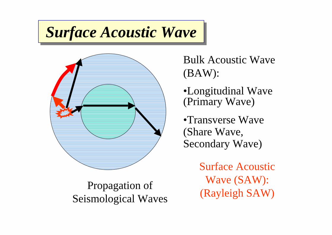
Surface Acoustic WaveSurface Acoustic Wave
Bulk Acoustic Wave (BAW):•Longitudinal Wave (Primary Wave)
•Transverse Wave (Share Wave, Secondary Wave)
Surface Acoustic Wave (SAW):
(Rayleigh SAW)Propagation of
Seismological Waves

Surface Acoustic Wave (SAW) Device
Vout
Vin
Piezoelectric substrate
Interdigital Transducers (IDT)
SAW
• Mass Production by Photolithography• Low loss, Miniature & Low price• Operation inVHF-UHF ranges
Line width λ/4=0.5μm (f=2GHz)

Impulse Response
• Independent Control of Amplitude and Phase Responses
SAW Transversal FiltersSAW Transversal Filters
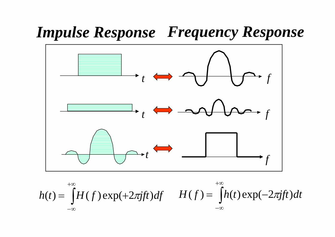
Impulse Response Frequency Response
t f
t
t
∫+∞
∞−
−= dtjftthfH )2exp()()( π∫+∞
∞−
+= dfjftfHth )2exp()()( π
f
f

Why Acoustic Wave Devices?Why Acoustic Wave Devices?
• Temperature Stability
]1)/[exp(0 −= kTqVII
cf. For Si, 3000ppm/oC
ppm100(1.9GHz) Freq.Center GSM1900
(200kHz)Bandwidth GSM≅
ppm 10day 1sec. 1
≅For watch,

Trade-Off Between Temp. Stability & Bandwidth
T driftω
(a) Wider Transition Bandwidth
(b) Narrower Transition Bandwidth
T driftω
Efficient Use of Frequency Resources ⇔ Narrow Transition Bandwidth (Or Improve Production Yield)

-45-40-35-30-25-20-15-10
-505
-0.2 -0.1 0 0.1 0.2 -1
-0.8-0.6-0.4-0.2
00.20.40.60.81
Tran
sfer
func
tion
in d
B
Relative Frequency
Tran
sfer
func
tion
in d
B
Fourier-Transform-Based DesignFourier-Transform-Based Design
Ripple due to truncation [Gibb’s Phenomenon]

t
w(t)t
thd(t)w(t)
hd(t)
Influence of TruncationInfluence of Truncation
∫+∞
∞−
−= ξξξ dfWHfH dw )()()(
Convolution Relation

Window FunctionsWindow Functions
t f
t f
Hamming:w(t)=0.54+0.46cos(2πt/T)
Blackmann:w(t)=0.42+0.5cos(2πt/T) +0.08cos(4πt/T)
Blackmann-Harris:w(t)=0.35875+0.48829cos(2πt/T)+0.14128cos(4πt/T)+0.01168cos(6πt/T)

0
0.2
0.4
0.6
0.8
1
-1 -0.8 -0.6 -0.4 -0.2 0 0.2 0.4 0.6 0.8 1
Wei
ght
Relative Position
HammingBlackmann
Blackmann-Harris

-120
-100
-80
-60
-40
-20
0
0 2 4 6 8 10
rectangularHammingBlackmann
Blackmann-Harris
Relative frequency
Am
plitu
de in
dB
Frequency Response of Window Functions with same T
Frequency Response of Window Functions with same T

-70-65-60-55-50-45-40-35-30-25-20-15-10-505
-0.2 -0.1 0 0.1 0.2
-0.8-0.6-0.4-0.2
00.20.40.60.81
-1
Tran
sfer
func
tion
in d
B
Relative frequency
Tran
sfer
func
tion
in d
B
Design by Fourier Transform + Window Function
Design by Fourier Transform + Window Function

454137 49 53
10 dB/div
FREQUENCY (MHz)43.7541.7539.75 45.7547.75
1 dB/div
50ns/div
FREQUENCY (MHz)
SAW Transversal Filter for CATV
Ref. 15dB

8070605040302010
0
67.5 68 68.5 69 69.5 70 70.5 71 71.5 72 72.5
Inse
rtion
loss
in d
B
Frequency in MHz
ExperimentSimulation
SAW IF Filter for IS-95SAW IF Filter for IS-95
Effects of Diffraction(2D SAW Propagation)
Courtesy of Fujitsu Labs.

(a) For Wide Aperture (b) Narrow Aperture
For Weighted IDT
Variation with Aperture Size

DAT
CD player Amp.
E
SR
SLR
Power source Load
E
SR
SLR
Power source Load
?
Low Frequency Design
High Frequency DesignHigh Zin and Low Zout for Minimum Interference
RL=RS for Maximum Power Transfer
How about for this case?

Triple Transit Echo (TTE)Triple Transit Echo (TTE)Interdigital Transducers (IDT)
• Mechanical Reflection + Electrical Regeneration ⇒Mutual-Connection Dependent
• Trade-Off: TTE ⇔ Insertion Loss• Intrinsic for Bidirectional IDTs

504540353025201510
50
-0.2 -0.1 0 0.1 0.2
Inse
rtion
loss
in d
B
Relative FrequencyS21 S21
0
Influence of TTEInfluence of TTE
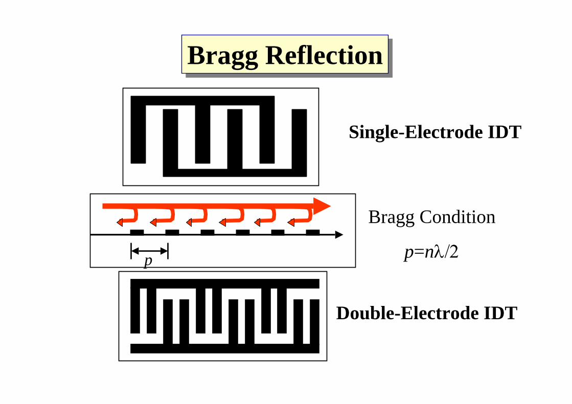
Bragg ReflectionBragg Reflection
p
Bragg Condition
p=nλ/2
Double-Electrode IDT
Single-Electrode IDT

absorber absorber
Guard electrode
Transversal SAW FilterTransversal SAW Filter
·Absorbers for Suppression of Reflection at Substrate Edges
·Dummy Electrode for Suppression of Reflection and Charge Concentration at Edges
·Guard Electrode for Suppression of EM Feedthrough

•••SAW Transversal FilterSAW Transversal FilterSAW Transversal Filter•SAW Unidirectional IDT Filters•••SAW Resonator FiltersSAW Resonator FiltersSAW Resonator Filters•••SAW Wireless Tags and SensorsSAW Wireless Tags and SensorsSAW Wireless Tags and Sensors
Contents

PLL/VCO
DuplexerIF-BPFRF-BPF
AntennaLNA
PA
φ
φ
PLL/VCO
A/D
D/A
A/D
D/A I
Q
I
Q
PLL/VCO
IF-BPFRF-BPF
Heterodyne Transceiver
Red:SAW Devices

Single Phase Unidirectional Transducer (SPUDTs)
Single Phase Unidirectional Transducer (SPUDTs)
(b) Inlayed Reflector(Complex but Wideband)
(a) Combination with Reflector(Simple but Narrowband)
• TTE Suppression• Low Loss• Frequency Response
⇒ Weighting for Excitation Profile
• Reflection Bandwidth < IDT Bandwidth ⇒Reflector Weighting
Independent Weighting to both Excitation and Reflection
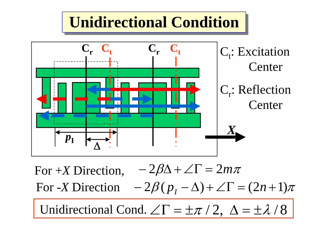
ΔpI
CtCrCtCr
For +X Direction, πβ m22 =Γ∠+Δ−πβ )12()(2 +=Γ∠+Δ−− npI
X
For -X Direction
Unidirectional Cond. 8/ ,2/ λπ ±=Δ±=Γ∠
Unidirectional ConditionUnidirectional Condition
Ct: Excitation Center
Cr: Reflection Center
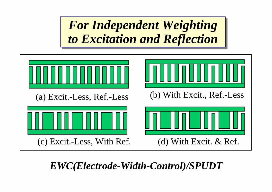
(d) With Excit. & Ref.
(b) With Excit., Ref.-Less
(c) Excit.-Less, With Ref.
(a) Excit.-Less, Ref.-Less
For Independent Weighting to Excitation and ReflectionFor Independent Weighting to Excitation and Reflection
EWC(Electrode-Width-Control)/SPUDT

Scat
terin
g C
oeff
icie
nt (d
B)
-40-35-30-25-20-15-10-50
0.8 0.85 0.9 0.95 1 1.05 1.1 1.15 1.2Relative Frequency
ψ=90o
ψ=0oLT=50pI
LI=20pI
κpI=0.02π
Filter Response with Reduced TTE
Low Loss and Suppressed TTE

Resonant SPUDT (R-SPUDTs)Resonant SPUDT (R-SPUDTs)
Reversed Reflection WeightingDirect Pulse
Multiple Echoes
Extension of Impulse Response

With Reflection
ω
Without Reflection
• Skirt Characteristics are Defined by Impulse Response Length
• Out-of-Band Characteristics are Defined by Excitation Profile

-60
-50
-40
-30
-20
-10
0
0.8 0.85 0.9 0.95 1 1.05 1.1 1.15 1.220
30
40
50
60
70
80
Relative Frequency
Scat
terin
g C
oeff
icie
nt (d
B)
τ
Gro
up D
elay
τ/τ
p
|S21|LT=0LI=34pI κpI|max=0.1π
Designed Example
Sharp Passband Shape + Flat Group Delay

-1-0.8-0.6-0.4-0.2
00.20.40.60.8
1
2 4 6 8 10 12 14 16 18 20
Excitation
ReflectionForward
Relative Position
Wei
ghtin
g Fu
nctio
n
Optimized weighted function
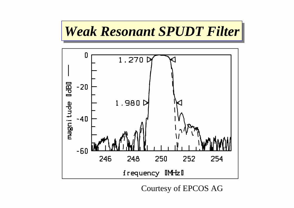
Courtesy of EPCOS AG
Weak Resonant SPUDT FilterWeak Resonant SPUDT Filter

Courtesy of EPCOS AG
Strong Resonant SPUDT FilterStrong Resonant SPUDT Filter

•••SAW Transversal FilterSAW Transversal FilterSAW Transversal Filter•••SAW Unidirectional IDT FiltersSAW Unidirectional IDT FiltersSAW Unidirectional IDT Filters•SAW Resonator Filters•••SAW Wireless Tags and SensorsSAW Wireless Tags and SensorsSAW Wireless Tags and Sensors
Contents

DuplexerRF-BPF
AntennaLNA
PA
φ
φ
PLL/VCO
A/D
D/A
A/D
D/A I
Q
I
Q
PLL/VCO
RF-BPF
Homodyne Transceiver
• Circuit Simplification ⇒ Reducing Component Number• No Image Signal ⇒ Relaxing Specs to RF Filters

(a) 1-Port Resonator
(b) 2-Port Resonator Filter
SAW Resonator

Piezoelectric Material
+
-
C0 η
Mk-1
V F
i v
C0
Lm
Rm
Cm
Analogies between V⇔F and I⇔v reduce toM⇔L, h⇔ R, k ⇔ 1/C
(a) Electric + Mechanical Circuit
Application of Electric Field to Piezoelectric Material,
(b) Electrical Equiv. Circuit
∫ ∝=++ VFvdtkvdtdvM η

(a) Electrical Equiv. Circuit (b) Equiv. Mechanical Circuit
•Resonance Frequency ωr=1/ CmLm•Anti-Resonance Frequency ωa=1/ Lm(Cm
-1+C0-1)-1
•Resonance Q (Steepness of Resonance) Q=ωrLm/Rm
•Capacitance Ratio (Weakness of Piezoelectricity)γ=C0/Cm=[(ωa/ωr)2-1]-1
⇒ Determine Insertion Loss and Skirt Characteristics
⇒ Determine Insertion Loss and Bandwidth
k η
M
F
k0C0
Lm
Rm
Cm

-0.6-0.4-0.20
0.20.40.60.81
0.96 0.98 1 1.02 1.04
Adm
ittan
ce [S
]
Frequency [GHz]
fr fa
•Resonance Frequency ωr=1/ CmLm•Anti-Resonance Frequency ωa=1/ Lm(Cm
-1+C0-1)-1

Transverse ModeTransverse Mode
Frequency
Adm
ittan
ce
ω r ω a
B
GIn-harmonic Resonance

Ladder-Type SAW FilterLadder-Type SAW Filter
Topology
• Low Loss• High Power Durability• Moderate Out-of-Band Rejection

ωr ωa
ω
Inse
rtion
Los
s (dB
)
Frequency ωInse
rtion
Los
s (dB
)
Frequency
ωr ωa
Parallel-ConnectionSeries-Connection
YsYp
Ys
Yp Yp
ω
Inse
rtion
Los
s (dB
)
Frequency
sp
p s
ωr
ωa=ωr
ωa
π-Connection
Null Generation
at Both Sides

Performance of Ladder-Type SAW FilterPerformance of Ladder-Type SAW Filter
W-CDMA-Rx
-50-45-40-35-30-25-20-15-10-50
1900 2000 2100 2200 2300 2400-5
-4
-3
-2
-1
0
Tx Rx
Frequency (MHz)
Fujitsu FAR-F6CP-2G1400-L21M
Scat
terin
g Pa
ram
eter
S21
(dB
)
Scat
terin
g Pa
ram
eter
S21
(dB
)

λ/4
λ/4
TX-port
RX-port
Antenna-port
SAW filter, TX
SAW filter, RXstrip line
strip line
F re q u e n c y [M H z]
Att
enua
tion
[dB]
0
-2 0
-4 0
-6 018 0 0 19 0 0 20 0 0
T x ba n d Rx ban d
F re q u e n c y [M H z]
Att
enua
tion
[dB]
0
-2 0
-4 0
-6 018 0 0 19 0 0 20 0 0
T x ba n d Rx ban d
Antenna Duplexer for US PCS
Rx Band
Tx Band
Courtesy of Fujitsu Labs.
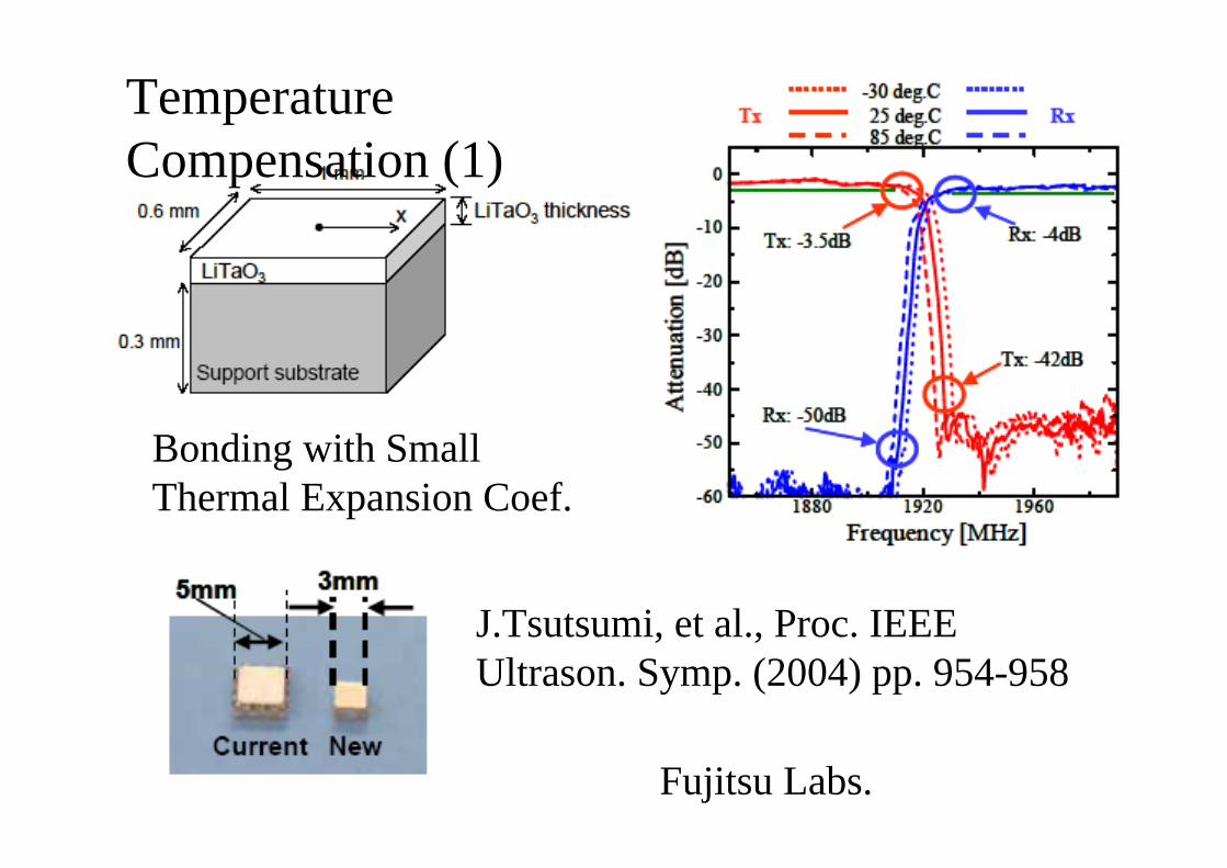
J.Tsutsumi, et al., Proc. IEEE Ultrason. Symp. (2004) pp. 954-958
Fujitsu Labs.
Bonding with Small Thermal Expansion Coef.
Temperature Compensation (1)
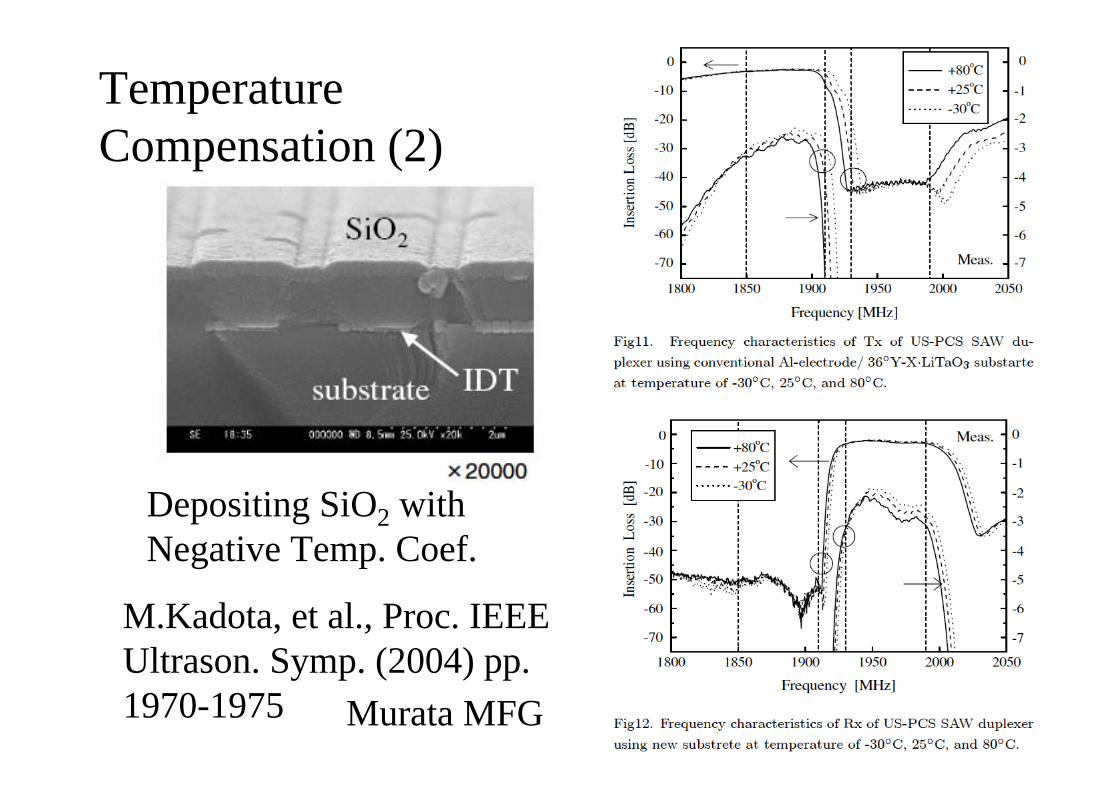
Temperature Compensation (2)
M.Kadota, et al., Proc. IEEE Ultrason. Symp. (2004) pp. 1970-1975 Murata MFG
Depositing SiO2 with Negative Temp. Coef.

• Good Out-of-Band Rejection
• Balun Function• Transformer Function• Low Loss• Lower Power Durability
Symmetrical & Anti-
symmetricalResonances
Double Mode SAW (DMS) Filter
arsω ωr
ω
Inse
rtio
n lo
ss (d
B)
Frequency
Electrically Isolated I/O

Structure of PitchPitch--Modulated IDT & ReflectorModulated IDT & ReflectorConventional Structure PitchPitch--Modulated StructureModulated Structure
IDT IDTREFECTOR
ModulatedModulated
ModulatedModulatedGap ControlledGap Controlled
Presented at IEEE 2004 UFFC Conf.

-8-7-6-5-4-3-2-10
800 850 900 950 1000 1050-80-70-60-50-40-30-20-10
0
Frequency [MHz]
Scat
terin
g pa
ram
eter
. S21
[dB
]
Scat
terin
g pa
ram
eter
. S21
[dB
]
DMS Filter with Modulated StructureDMS Filter with Modulated Structure
Fujitsu FAR-F5EB-942M50-B28E
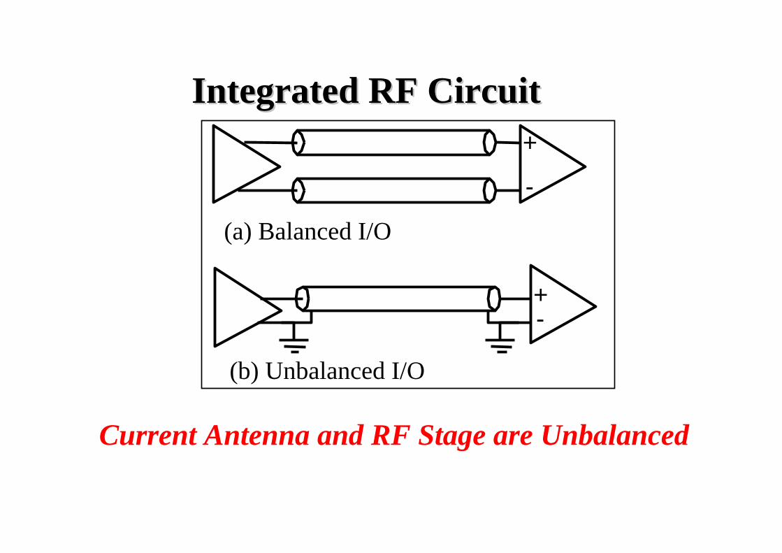
Integrated RF Circuit Integrated RF Circuit
Current Antenna and RF Stage are Unbalanced
(a) Balanced I/O
(b) Unbalanced I/O
+
-
+-

Front-endBPF LNA
Inter-stageBPF IF-BPFMixer
Front-endBPF LNA IF-BPFMixer
Balun IF-Amp
IF-Amp
Discrete SAW Filter & Balun
Inter-stageBPF
SAW Filter with Balun Function

Vout+
Vout-
Vin
DMS Filter (Ideally No Common Signal)
Acoustically Coupled but Electrically Isolated
Common Signal Generation by Parasitics
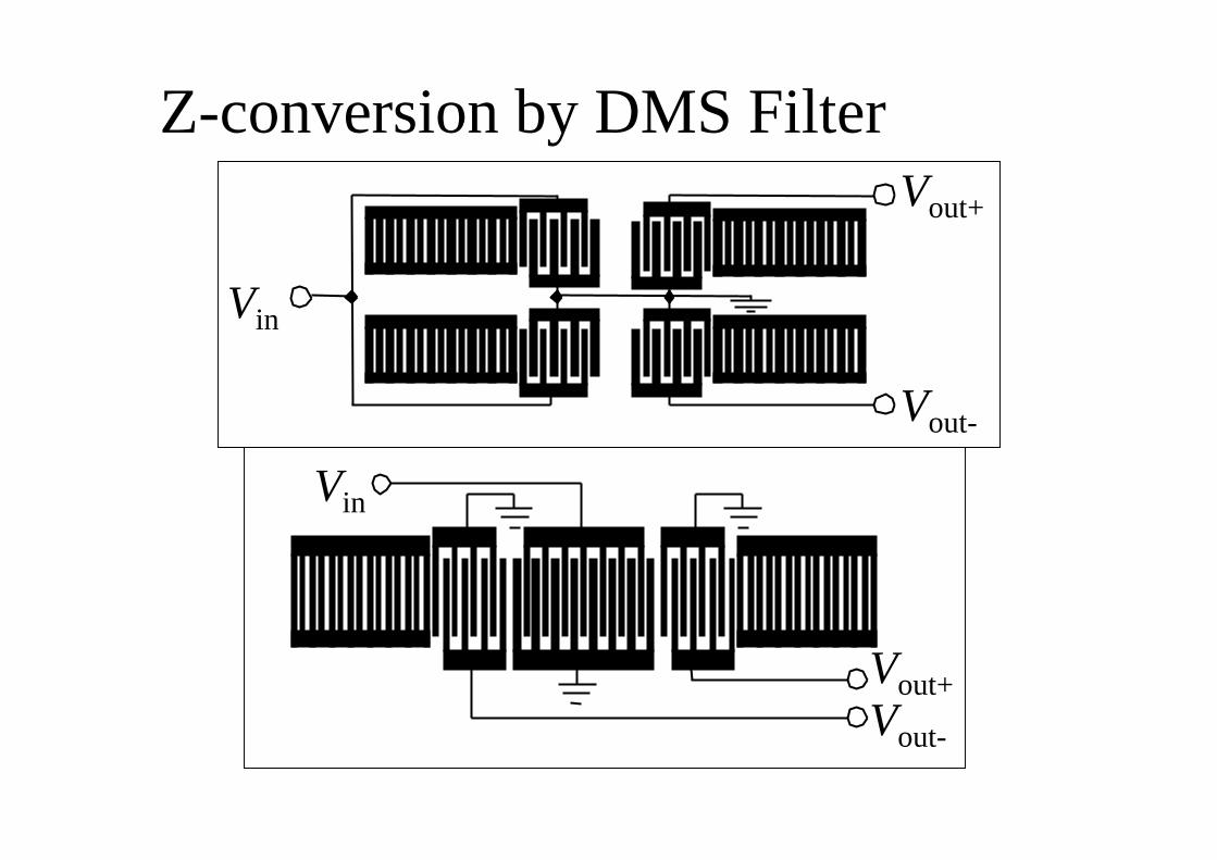
Vout+
Vout-
Vin
Vin
Vout+Vout-
Z-conversion by DMS Filter

•••SAW Transversal FilterSAW Transversal FilterSAW Transversal Filter•••SAW Unidirectional IDT FiltersSAW Unidirectional IDT FiltersSAW Unidirectional IDT Filters•••SAW Resonator FiltersSAW Resonator FiltersSAW Resonator Filters•SAW Wireless Tags and Sensors
Contents
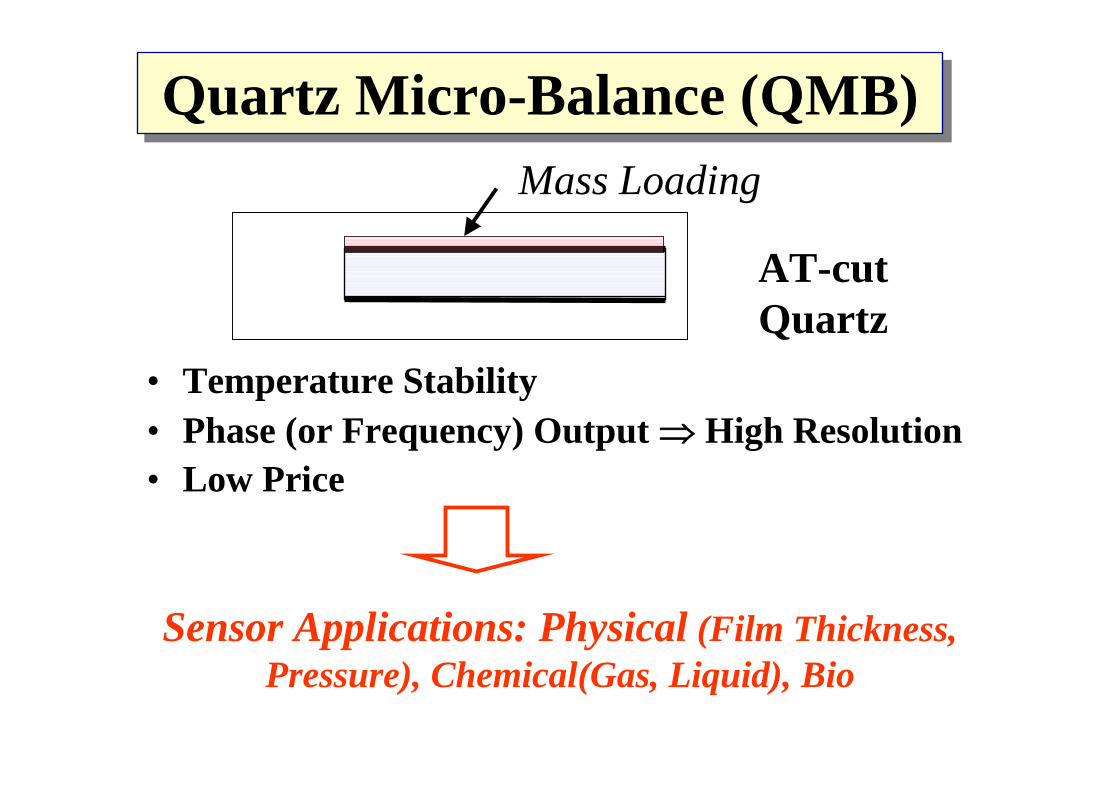
AT-cut Quartz
Quartz Micro-Balance (QMB)Quartz Micro-Balance (QMB)
• Temperature Stability• Phase (or Frequency) Output ⇒ High Resolution• Low Price
Mass Loading
Sensor Applications: Physical (Film Thickness, Pressure), Chemical(Gas, Liquid), Bio

Vout
Vin
Piezo-Substrate
IDT
SAW
• High f (Δ f =−K f02Δm) ⇒ High Sensitivity
• Moderate Temperature Stability• Surface Protection (Packaging) ?
SAW SensorSAW Sensor
Area 1 mm2 & f0=1 GHz give K f0 ~ 107 / kg⇒ 1 ppm of f deviation=Resolution 0.1 pg.

SAW Sensor Configuration
Frequency Detection
Phase Detection
Δφ~ Δm
Δf ~ Δm

SAW Chemical Sensor
• Sensitive Layer: A calixarene (10 nm)• Object: tetrachloroethene• f0: 434 MHz
Time [min]Freq
uenc
y D
evia
tion
[Hz]
0
-200
-400
-6000 10 20 30
Con
tent
[ppm
]
0
20
40
60

Pattern Recognisition with Sensor Array
Sensor : Sensitive FilmA Calix[4]resorcinearene 1B Calix[4]resorcinearene 2C Cyclodextrine-functiona-
lized polymer 1D Cyclodextrine-functiona-
lized polymer 2
C DA B
Sensor Array
p-xylenem-xylene
humidity

What is SAW ID-TAG?
Antenna
Transceiver
• Large Group Delay (Separation with Environmental Echoes)
• Wireless, Batteryless
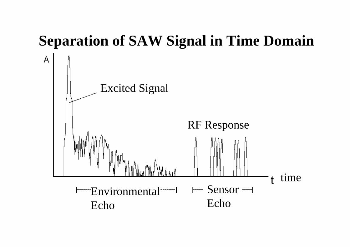
Separation of SAW Signal in Time Domain
Excited Signal
Environmental Echo
Sensor Echo
RF Response
time

Which Frequency?
•5.2 GHz (ISM Band)Wideband (100MHz), Short Accessible Distance (<1m), Hard to Realize SAW Devices
•2.45 GHz (ISM Band) Wideband(22MHz), Short Accessible Distance (2-3m), Price of SAW Devices?
•433.92 MHz (RKE Band) Narrowband(1.7MHz), Long Accessible Distance (>10m), Low SAW Device Cost

SAW ID Tag with 5 reflectors in one track (f0 = 2.45 GHz) using pulse position coding
2nd reflector
Possible coding positionof 1st reflector
1st reflecor
AntennaPossible coding positionof 2nd reflector
Tag by
Pulse position coding schema

OIS - W
Baumer Ident (2.45 GHz ISM)

Brake temperature of a train entering a station
60,00
70,00
80,00
90,00
100,00
Time
Tem
pera
ture
°C
reader antenna
Brake (with attached SAW temperature transponder, not seen)

The dynamic range of monitoringthe torque with SAW can be up to several tenths of kHz
SAW Torque Sensor
strain in ‰
phas
e di
ffere
nce
in d
eg.
0
50
100
150
200
150
0 0.05 0.10 0.15 0.20
SAWsensors
rotatingshaft
Tx antennas
Rx antennas
measurement set-up

SAW pressure sensor
diaphragm
adhesive
cover-plateclosed cavity withreference-pressure
antenna
1.001.201.401.601.802.002.202.402.602.803.00
14:30
:5514
:30:59
14:31
:0414
:31:09
14:31
:1314
:31:18
14:31
:2214
:31:27
14:31
:3214
:31:36
14:31
:41
pressure[Bar]
time
Two Track Railway Crossing
Adjacent Water Channel