introduction to solid modeling parametric...
TRANSCRIPT

Ken Youssefi Mechanical Engineering Dept. 1
Introduction to Solid Modeling
Parametric Modeling

Ken Youssefi Mechanical Engineering Dept. 2
Why draw 3D Models?
• 3D models are easier to interpret.
• Simulation under real-life conditions.
• Less expensive than building a physical model.
• 3D models can be used to perform finite element
analysis (stress, deflection, thermal…..).
• 3D models can be used directly in manufacturing,
Computer Numerical Control (CNC).
• Can be used for presentations and marketing.

Ken Youssefi Mechanical Engineering Dept. 3
3D Modeling
• Wireframe modeling
• Surface modeling
• Solid modeling
There are three basic types of three-dimensional computer
geometric modeling methods:

Ken Youssefi Mechanical Engineering Dept. 4
Wireframe Modeling
• Contains information about the locations of all the points
(vertices) and edges in space coordinates.
• Each vertex is defined by x, y, z coordinate.
• Edges are defined by a pair of vertices.
• Faces are defined as three or more edges.
• Wireframe is a collection of edges, there is no skin
defining the area between the edges.

Ken Youssefi Mechanical Engineering Dept. 5
Wireframe Modeling
• Can quickly and efficiently convey information than multiview drawings.
• The only lines seen are the intersections of surfaces.
• Can be used for finite element analysis.
• Can be used as input for CNC machines to generate simple parts.
• Contain most of the information needed to create surface, solid and higher order models
Advantages:
Ken Youssefi Mechanical Engineering Dept. 6
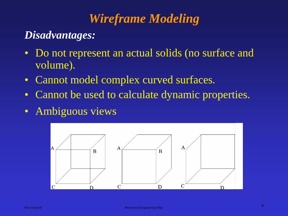
Wireframe Modeling
• Do not represent an actual solids (no surface and volume).
• Cannot model complex curved surfaces.
• Cannot be used to calculate dynamic properties.
• Ambiguous views
Disadvantages:
Ken Youssefi Mechanical Engineering Dept. 7
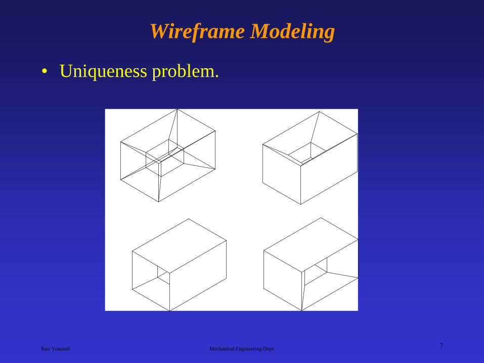
Wireframe Modeling
• Uniqueness problem.

Ken Youssefi Mechanical Engineering Dept. 8
Surface Modeling
• Surface models define the surface features, as well
as the edges, of objects.
• A mathematical function describes the path of a
curve (parametric techniques).
• Surfaces are edited as single entities.
A surface model represents the skin of an object,
these skins have no thickness or material type.
Ken Youssefi Mechanical Engineering Dept. 9
Surface Modeling
• Eliminates ambiguity and non-uniqueness present in wireframe models by hiding lines not seen.
• Renders the model for better visualization and presentation, objects appear more realistic.
• Provides the surface geometry for CNC machining.
• Provides the geometry needed for mold and die design.
• Can be used to design and analyze complex free-formed surfaces (ship hulls, airplane fuselages, car bodies, …).
• Surface properties such as roughness, color and reflectivity can be assigned and demonstrated.
Advantages:

Ken Youssefi Mechanical Engineering Dept. 10
Surface Modeling
• Surface models provide no information about the
inside of an object.
• Complicated computation, depending on the
number of surfaces
Disadvantages:
Ken Youssefi Mechanical Engineering Dept. 11
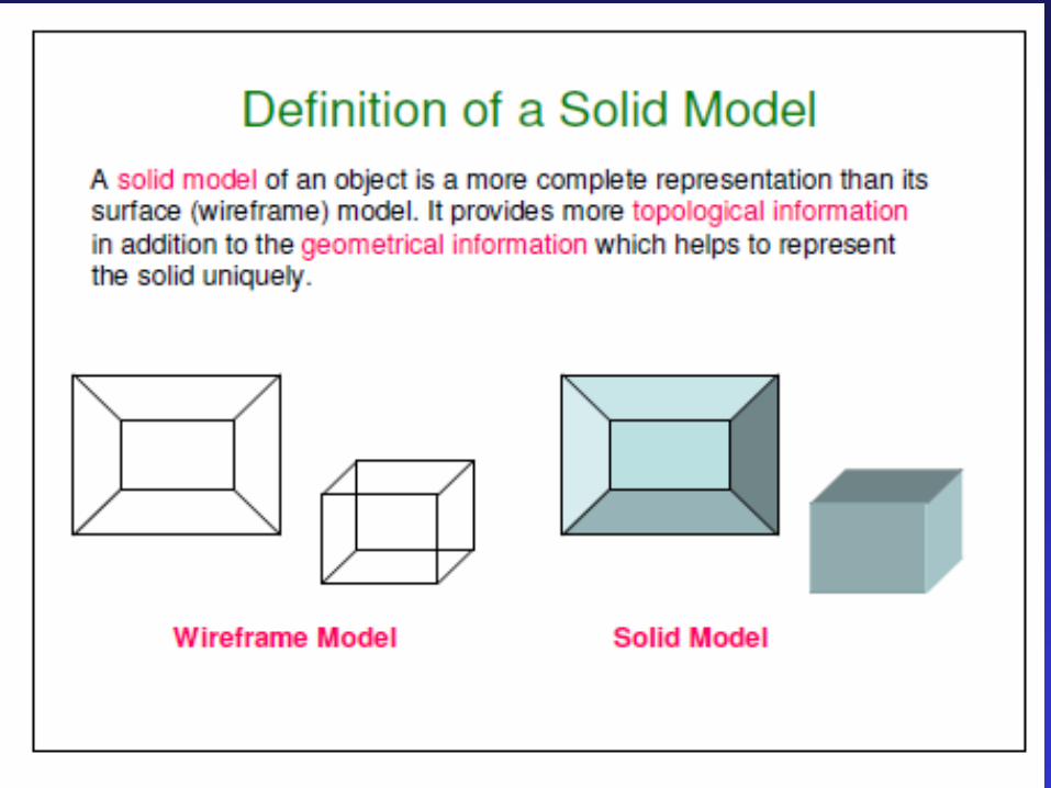
Solid Models
• Has all the advantages of surface models (uniqueness,
non-ambiguous, realistic, surface profile) plus
volumetric information.
• Allows the designer to create multiple options for a
design.
• 2D standard drawings, assembly drawing and exploded
views are generated form the 3D model.
In the solid modeling, the solid definitions include vertices
(nodes), edges, surfaces, weight, and volume. The model is a
complete and unambiguous representation of a precisely
enclosed and filled volume.
Advantages:

Ken Youssefi Mechanical Engineering Dept. 12
Solid Models
• Can easily be exported to different Finite Element Methods programs for analysis.
• Can be used in newly manufacturing techniques; computer integrated manufacturing (CIM), computer aided manufacturing (CAM) and design for manufacturability ans assembly (DFM, DFA)
• Mass and volumetric properties of an object can be easily obtained; total mass, mass center, area and mass moment of inertia, volume, radius of gyration, …
Advantages:

Ken Youssefi Mechanical Engineering Dept. 13
Volumetric and Mass properties of an object can be easily obtained.
Corresponding mass properties are obtained if density is included.
Ken Youssefi Mechanical Engineering Dept. 14
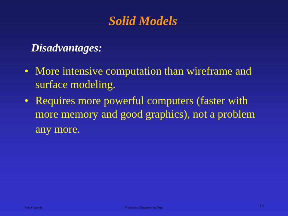
Solid Models
• More intensive computation than wireframe and
surface modeling.
• Requires more powerful computers (faster with
more memory and good graphics), not a problem
any more.
Disadvantages:
Ken Youssefi Mechanical Engineering Dept. 15

Ken Youssefi Mechanical Engineering Dept. 16
Ken Youssefi Mechanical Engineering Dept. 17
Ken Youssefi Mechanical Engineering Dept. 18
Ken Youssefi Mechanical Engineering Dept. 19

Ken Youssefi Mechanical Engineering Dept. 20

Ken Youssefi Mechanical Engineering Dept. 21

Ken Youssefi Mechanical Engineering Dept. 22
Ken Youssefi Mechanical Engineering Dept. 23
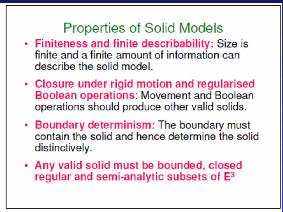
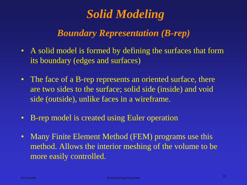
Solid Modeling
Boundary Representation (B-rep) • A solid model is formed by defining the surfaces that form
its boundary (edges and surfaces)
• The face of a B-rep represents an oriented surface, there
are two sides to the surface; solid side (inside) and void
side (outside), unlike faces in a wireframe.
• B-rep model is created using Euler operation
• Many Finite Element Method (FEM) programs use this
method. Allows the interior meshing of the volume to be
more easily controlled.

Ken Youssefi Mechanical Engineering Dept. 24
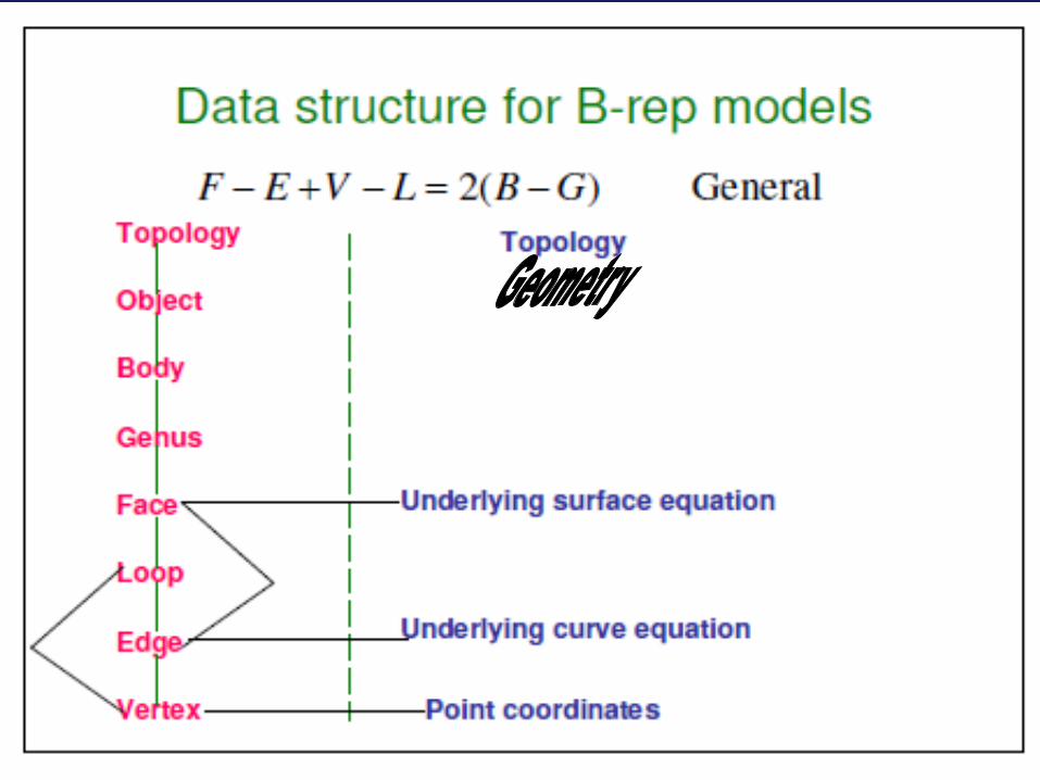
B-Rep Data Structure
Ken Youssefi Mechanical Engineering Dept. 25
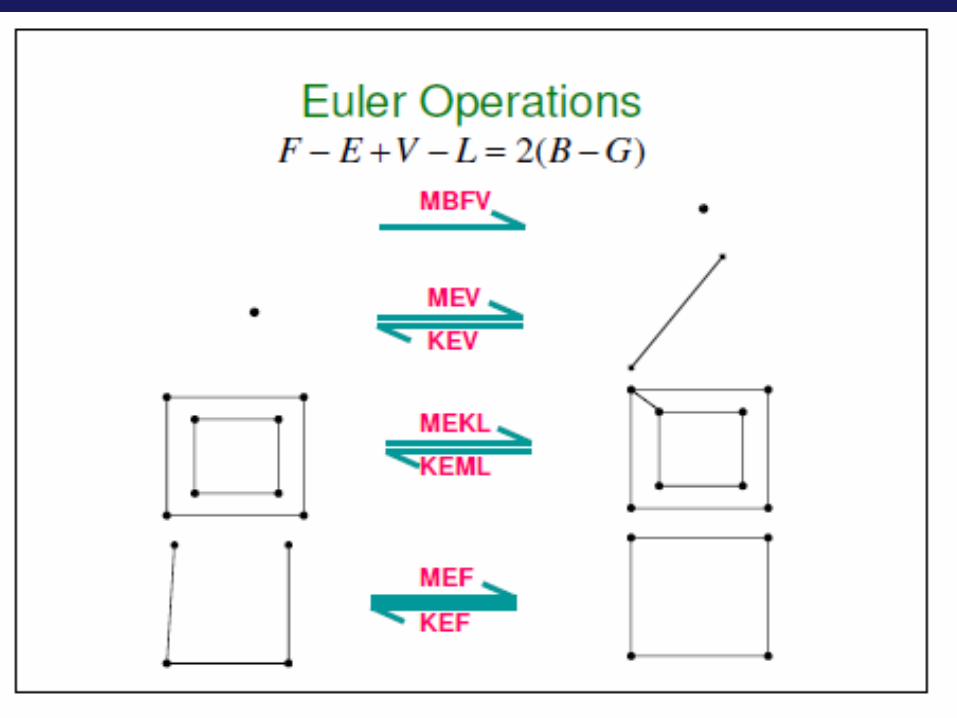
Euler Operators
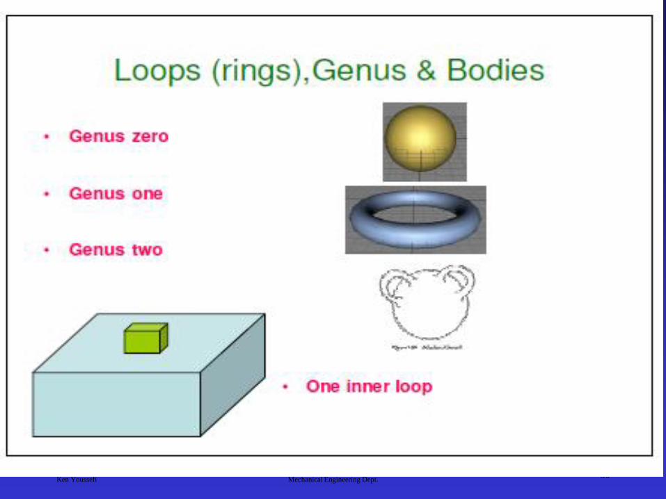
Geometric entities stored in B-Rep data structures are the
shell, face, loop, edge, and vertex.
Operators are needed to manipulate these entities (e.g., an
operator to make an edge, an operator to delete an edge,…)

Ken Youssefi Mechanical Engineering Dept. 26

Ken Youssefi Mechanical Engineering Dept. 27

Ken Youssefi Mechanical Engineering Dept. 28

Ken Youssefi Mechanical Engineering Dept. 29
Ken Youssefi Mechanical Engineering Dept. 30
Ken Youssefi Mechanical Engineering Dept. 31
Ken Youssefi Mechanical Engineering Dept. 32
Ken Youssefi Mechanical Engineering Dept. 33
Ken Youssefi Mechanical Engineering Dept. 34

Ken Youssefi Mechanical Engineering Dept. 35
Ken Youssefi Mechanical Engineering Dept. 36

Ken Youssefi Mechanical Engineering Dept. 37

Ken Youssefi Mechanical Engineering Dept. 38

Ken Youssefi Mechanical Engineering Dept. 39
Ken Youssefi Mechanical Engineering Dept. 40
Ken Youssefi Mechanical Engineering Dept. 41
Ken Youssefi Mechanical Engineering Dept. 42

Ken Youssefi Mechanical Engineering Dept. 43
Ken Youssefi Mechanical Engineering Dept. 44

Ken Youssefi Mechanical Engineering Dept. 45

Ken Youssefi Mechanical Engineering Dept. 46
Ken Youssefi Mechanical Engineering Dept. 47

Ken Youssefi Mechanical Engineering Dept. 48

Ken Youssefi Mechanical Engineering Dept. 49
Constructive Solid Geometry, CSG
• CSG defines a model in terms of combining basic and generated (using extrusion and sweeping operation) solid shapes.
• CSG uses Boolean operations to construct a model (George Boole, 1815-1864, invented Boolean algebra).
• There are three basic Boolean operations:
Union (Unite, join) - the operation combines two volumes included in the different solids into a single solid.
Subtract (cut) - the operation subtracts the volume of
one solid from the other solid object.
Intersection - the operation keeps only the volume
common to both solids

Ken Youssefi Mechanical Engineering Dept. 50
Primitive Solids and Boolean Operations
The basic primitive solid:

Ken Youssefi Mechanical Engineering Dept. 51
Primitive Solids
The location of
the insertion base
or base point and
default axes
orientation.

Ken Youssefi Mechanical Engineering Dept. 52
Boolean Operations
Union
Subtract
Intersection

Ken Youssefi Mechanical Engineering Dept. 53
Implementing Boolean Operation
Consider solids A and B.

Ken Youssefi Mechanical Engineering Dept. 54
Boolean Operation
The intersection curves of all the faces of solid A and B
are calculated. These intersections are inscribed on the
associated faces of the two solids.

Ken Youssefi Mechanical Engineering Dept. 55
Boolean Operation
The faces of solid A are classified according to their relative location
with respect to solid B. Each face is tested to determine whether it is
located inside, outside, or on the boundary surface of solid B.
The faces in group A1 are outside solid B, and those of group B1 are
inside solid A.

Ken Youssefi Mechanical Engineering Dept. 56
Boolean Operation
Groups of faces are collected according to the specific
Boolean operation and the unnecessary face groups are
eliminated. For example, for union operation, group A1 and
B2 are collected and A2 and B1 are eliminated.

Ken Youssefi Mechanical Engineering Dept. 57
Boolean Operation The two solids are glued at their common boundary.

Ken Youssefi Mechanical Engineering Dept. 58
Union
Plan your modeling strategy
before you start creating the
solid model
Solid Modeling Example Using CSG
Cut
Cut

Ken Youssefi Mechanical Engineering Dept. 59
Creating Solid Models
Parametric Modeling Concept
• Parametric is a term used to describe a dimension’s ability to change the shape of model geometry if the dimension value is modified.
• Feature-based is a term used to describe the various components of a model. For example, a part can consists of various types of features such as holes, grooves, fillets, and chamfers.
• Parametric modeler are featured-based, parametric, solid modeling design program: SolidWorks, Pro-Engineer, Unigraphics (CSG and parametric), …..

Ken Youssefi Mechanical Engineering Dept. 60
Design Intent
• In parametric modeling, dimensions control the model.
• Design intent is how your model will react when dimension values are changed.

Ken Youssefi Mechanical Engineering Dept. 61
Design Intent
Remember that the placement of dimensions is very important
because they are being used to drive the shape of the geometry. If
the 2.5 in. vertical dimension increases, the 2.5 in. flat across the
chamfer will be maintained, but its angle will change.
The drawing shows the intent of the
designer that the inclined plane
(chamfer) should have a flat area
measuring 2.5 inches and that it
should start at a point 1.25 inches
from the base of the drawing. These
parameters are what the designer
deemed significant for this model.
2.50
4.00
1.25
2.50
Example:

Ken Youssefi Mechanical Engineering Dept. 62
Design Intent
In this drawing, what is important to
the designer is the vertical location and
horizontal dimension of the chamfer,
rather than the flat of the chamfer. 2.50
4.00
1.25
2.125
In the last drawing, the designer calls
for a specific angle for the chamfer.
In this case the angle of the chamfer
should be dimensioned.
2.50
4.00
1.75
30.0O

Ken Youssefi Mechanical Engineering Dept. 63
Design Intent

Ken Youssefi Mechanical Engineering Dept. 64
Design Notes
• Keep in mind that dimensioning scheme can be
changed at any time. You are not locked into a
specific design. You can also design without
dimensioning, rough out a sketch, and then later
go back and fully define it.
• Do not be concerned with dimensioning to datum
or stacked tolerances in the part. Those issues can
be addressed in the drawing layout. Be more
concerned with your design intent.

Ken Youssefi Mechanical Engineering Dept. 65
Boolean Versus Parametric Modeling
The ability to go back on some earlier stage in the design
process and make changes by editing a sketch or changing
some dimensions is extremely important to a designer. This is
the main advantage of a parametric (SolidWorks, Unigraphics,
Inventor, Pro-Engineer) over a non-parametric modeler
(AutoCAD 3D modeler – Boolean operation)

Ken Youssefi Mechanical Engineering Dept. 66
Boolean Versus Parametric Modeling
Example:
Let’s assume that it is desired to design a part consisting of a
ring with a certain thickness and a series of counterbore holes
along the perimeter.

Ken Youssefi Mechanical Engineering Dept. 67
Boolean Versus Parametric Modeling
Boolean operation
Make the base part by creating two
cylinders and subtract the small one
from the large one
Create the solid geometry that will
become the counterbore holes and
generate the pattern.

Ken Youssefi Mechanical Engineering Dept. 68
Boolean Versus Parametric Modeling
Position the pattern about the perimeter of the
base part. Locating the holes is critical to
creating an accurate solid model.
What would happen if you had to come back to this part to change
the thickness of the ring or size of the counterbore holes?
Since Boolean operation was used to create the part, changing the
thickness would not increase the height of the holes. There is no
association between the thickness and the hole pattern location.
Subtract the pattern from the base part to
create the actual holes.
Ken Youssefi Mechanical Engineering Dept. 69
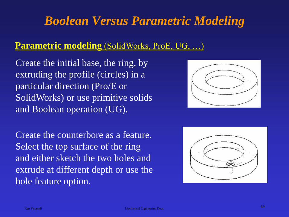
Boolean Versus Parametric Modeling
Parametric modeling (SolidWorks, ProE, UG, …)
Create the initial base, the ring, by
extruding the profile (circles) in a
particular direction (Pro/E or
SolidWorks) or use primitive solids
and Boolean operation (UG).
Create the counterbore as a feature.
Select the top surface of the ring
and either sketch the two holes and
extrude at different depth or use the
hole feature option.

Ken Youssefi Mechanical Engineering Dept. 70
Boolean Versus Parametric Modeling
The next step would be to pattern the
hole. The pattern would actually be
considered a feature in itself, and
would have its set of parametric
variables, such as the number of
copies and the angle between copies.
The model created would be identical to the one created
using Boolean operation, but with intelligence built into
the model.
Ken Youssefi Mechanical Engineering Dept. 71
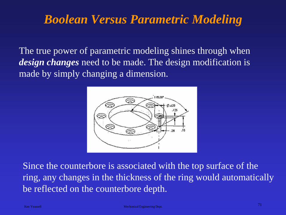
Boolean Versus Parametric Modeling
The true power of parametric modeling shines through when
design changes need to be made. The design modification is
made by simply changing a dimension.
Since the counterbore is associated with the top surface of the
ring, any changes in the thickness of the ring would automatically
be reflected on the counterbore depth.
Ken Youssefi Mechanical Engineering Dept. 72
Sketching and Features
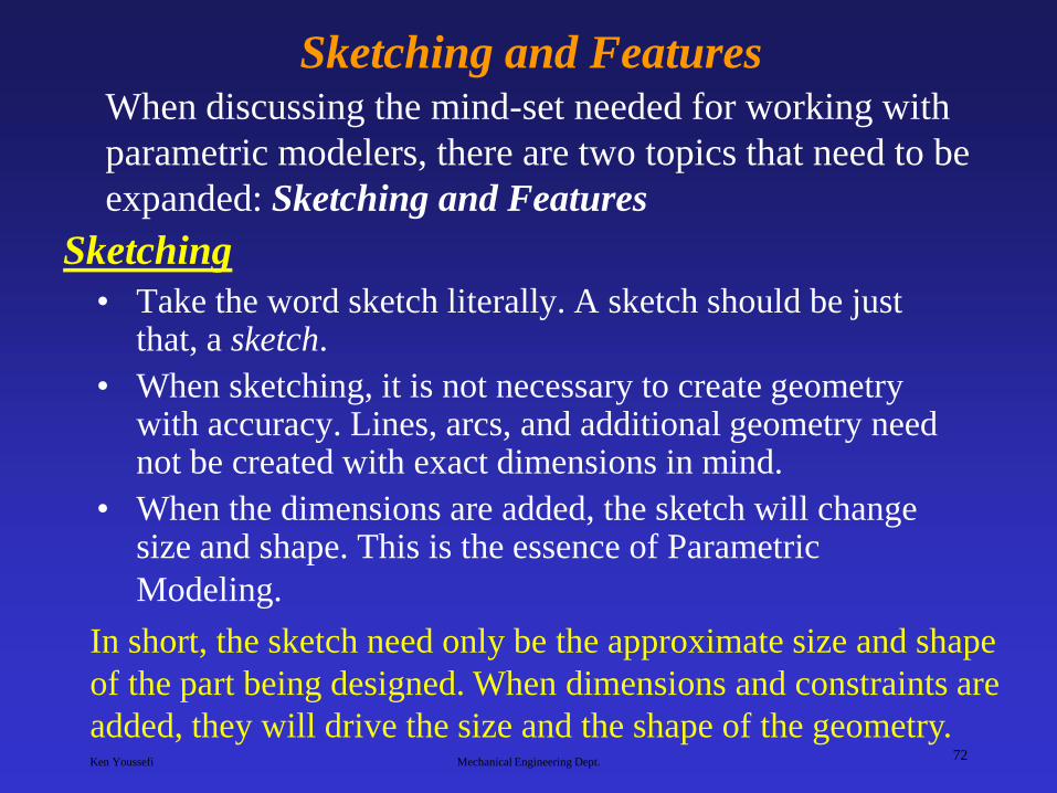
• Take the word sketch literally. A sketch should be just that, a sketch.
• When sketching, it is not necessary to create geometry with accuracy. Lines, arcs, and additional geometry need not be created with exact dimensions in mind.
• When the dimensions are added, the sketch will change size and shape. This is the essence of Parametric
Modeling.
When discussing the mind-set needed for working with
parametric modelers, there are two topics that need to be
expanded: Sketching and Features
Sketching
In short, the sketch need only be the approximate size and shape
of the part being designed. When dimensions and constraints are
added, they will drive the size and the shape of the geometry.

Ken Youssefi Mechanical Engineering Dept. 73
Sketching and Features
• Sketched Feature
Features
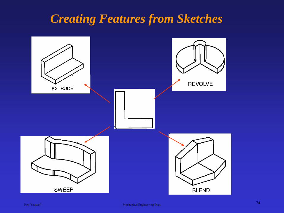
Create a feature from the sketch by extruding,
revolving, sweeping, lofting and blending.
2.75
2.5 1.0
.25
.75
Create a 2D sketch.
Revolved feature Extruded feature
Ken Youssefi Mechanical Engineering Dept. 74
Creating Features from Sketches
Ken Youssefi Mechanical Engineering Dept. 75
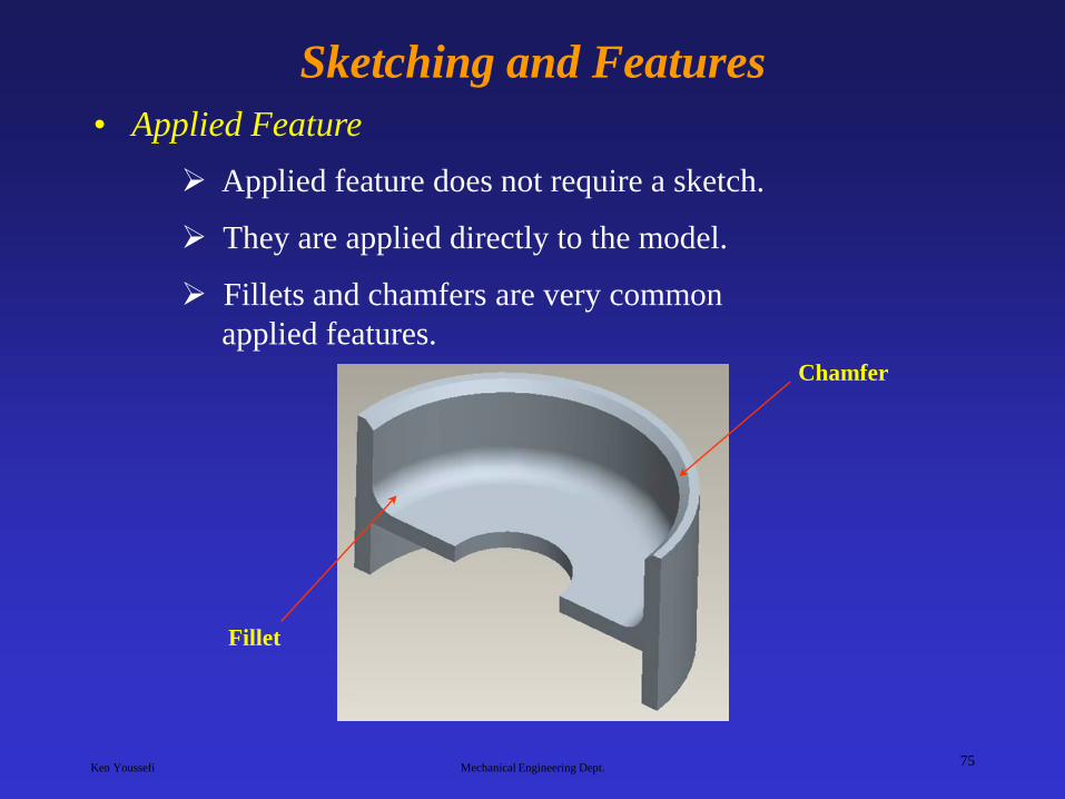
Sketching and Features
• Applied Feature
Applied feature does not require a sketch.
They are applied directly to the model.
Fillets and chamfers are very common
applied features. Chamfer
Fillet
Ken Youssefi Mechanical Engineering Dept. 76
Summary – Solid Modeling Methods
• Primitive creation modeling
A solid model is created by retrieving primitive solids and performing Boolean operations
• Sweeping function
Creates a solid by translating, revolving or sweeping a predefined 2D shape (Sketching).
If geometric and dimensional constraints are imposed, it is called Parametric Modeling.
• Feature-based Modeling
Models a solid by using familiar shapes; holes, slots, grooves, pockets, chamfers, fillets…..
Ken Youssefi Mechanical Engineering Dept. 77
Summary – Solid Modeling Methods
• Modifying functions
Rounding (or blending) and lifting.
• Boundary Modeling
Lower entities of a solid (vertices, edges and
faces) are directly manipulated.
Ken Youssefi Mechanical Engineering Dept. 78
Sketching
• Take the word sketch literally. A sketch should
be just that, a sketch.
• Sketches are able to capture the designer’s intent
for the part like no other technique.
• The sketch is the best tool for creating solids
because of flexibility in shapes and the ability to
edit.
• Ideal for creating unusual freeform shapes.

Ken Youssefi Mechanical Engineering Dept. 79
Sketching
• A sketch is a set of two dimensional curves joined
in a string that when swept or extruded forms a
solid body.
• When sketching it is not necessary to create
geometry with accuracy.
• Lines, arcs, and additional geometry need not be
created with exact dimensions in mind.

Ken Youssefi Mechanical Engineering Dept. 80
Sketching
• When the dimensions are added, the sketch will
change size and shape. This is the essence of
parametric modeling
• In short, the sketch need only be the approximate
size and shape of the part being designed. The
geometric constraints and dimensions, when
added, will drive the size and the shape of the
geometry.
• Curves are parametrically associated to each other
and the solid that is created by them.