introduction to rf undulators 11 th of march 2015 juergen pfingstner
TRANSCRIPT

Introduction to RF undulators
11th of March 2015Juergen Pfingstner
Content
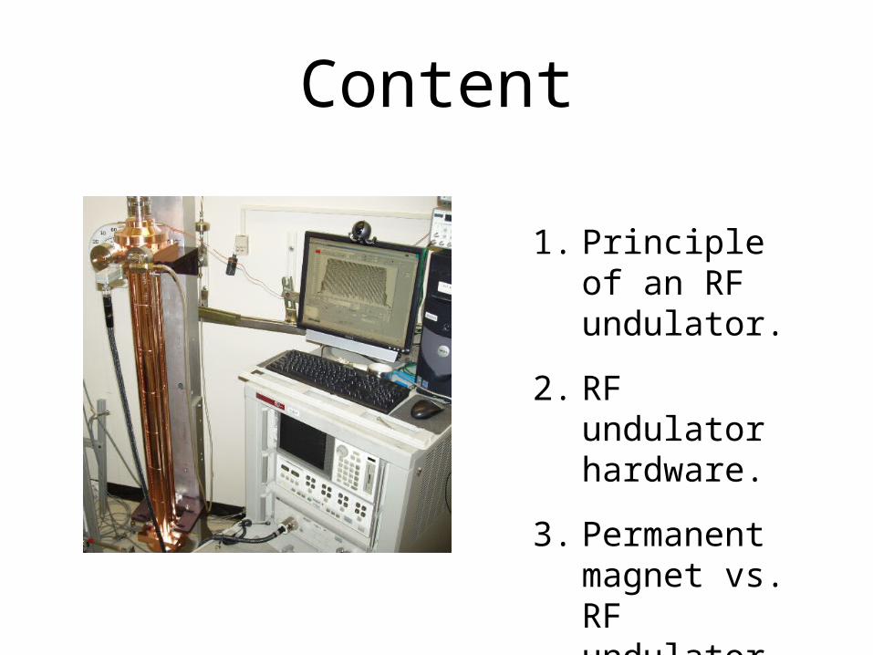
1. Principle of an RF undulator.
2. RF undulator hardware.
3. Permanent magnet vs. RF undulator.
1. Principle of an RF undulator
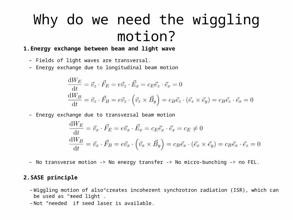
Why do we need the wiggling motion?1. Energy exchange between beam and light wave
– Fields of light waves are transversal.– Energy exchange due to longitudinal beam motion
– Energy exchange due to transversal beam motion
– No transverse motion -> No energy transfer -> No micro-bunching -> no FEL.
2. SASE principle
– Wiggling motion of also creates incoherent synchrotron radiation (ISR), which can be used as “seed light”.
– Not “needed” if seed laser is available.

Undulator and resonance wave length λR
• The necessary transverse beam motion is created via an additional sinusoidal magnetic field of an undulator.
• The energy exchange between the beam and the light is optimal for the light with wavelength λR in an undulator with the parameters λu, K and a beam with relativistic factor γ.
Undulator period λu:• Baseline for hard XbFEL 1.5 cm
Undulator parameter:• K = 0.934 B0 [T] λu [cm]• Baseline for hard XbFEL 1.4• Limited above by light quality.
Beam energy: • γ = E/(m0c2)• Baseline for hard XbFEL 6 GeV

Permanent magnet undulators• In all operational and planned FELs this external field is created with
permanent magnet undulators.
• The minimum period λu reachable is about 1.5 cm (SACLA 1.8 cm, SwissFEL 1.5 cm).
• For λu of 1.5 cm, K values of >2 can be reached if desired.
Picture taken from: Centre Laser Infrarouge d'Orsay
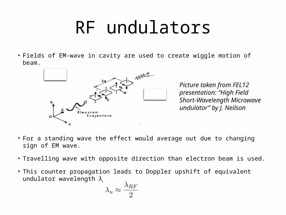
RF undulators• Fields of EM-wave in cavity are used to create wiggle motion of beam.
• For a standing wave the effect would average out due to changing sign of EM wave.
• Travelling wave with opposite direction than electron beam is used.
• This counter propagation leads to Doppler upshift of equivalent undulator wavelength λu.
Picture taken from FEL12 presentation: “High Field Short-Wavelength Microwave undulator” by J. Neilson
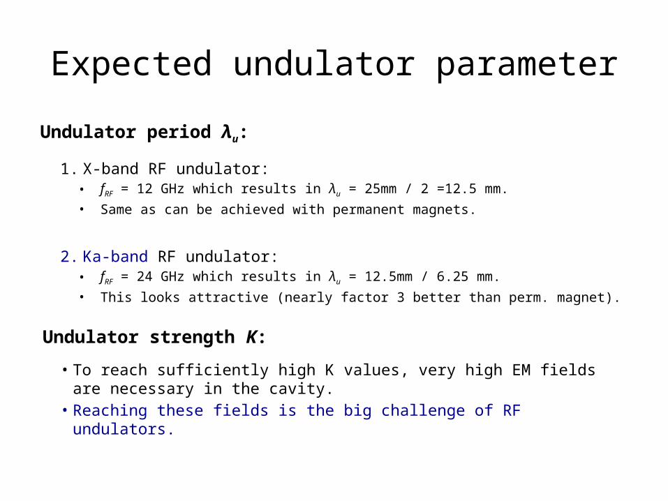
Expected undulator parameterUndulator period λu:
1. X-band RF undulator:• fRF = 12 GHz which results in λu = 25mm / 2 =12.5 mm. • Same as can be achieved with permanent magnets.
2. Ka-band RF undulator: • fRF = 24 GHz which results in λu = 12.5mm / 6.25 mm. • This looks attractive (nearly factor 3 better than perm. magnet).
Undulator strength K:
• To reach sufficiently high K values, very high EM fields are necessary in the cavity.
• Reaching these fields is the big challenge of RF undulators.
2. RF undulator hardware
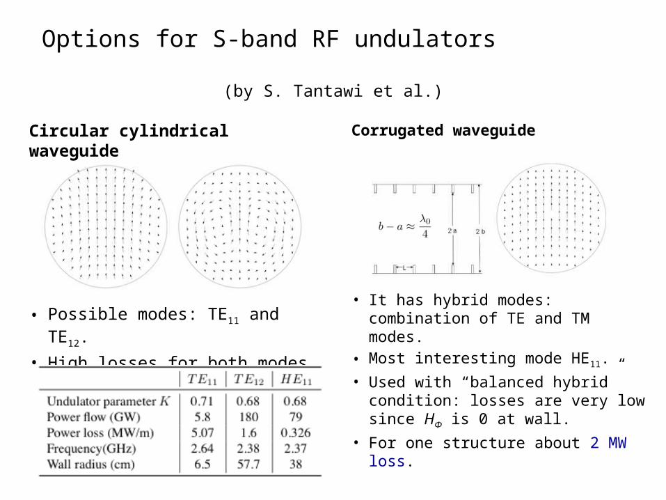
Options for S-band RF undulators (by S. Tantawi et al.)
Circular cylindrical waveguide
• Possible modes: TE11 and TE12.• High losses for both modes.
Corrugated waveguide
• It has hybrid modes: combination of TE and TM modes.
• Most interesting mode HE11.• Used with “balanced hybrid”
condition: losses are very low since HΦ is 0 at wall.
• For one structure about 2 MW loss.
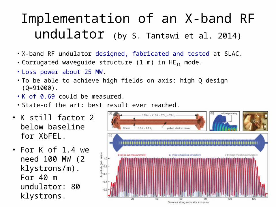
Implementation of an X-band RF undulator (by S. Tantawi et al. 2014)
• X-band RF undulator designed, fabricated and tested at SLAC.• Corrugated waveguide structure (1 m) in HE11 mode.• Loss power about 25 MW. • To be able to achieve high fields on axis: high Q design (Q=91000).• K of 0.69 could be measured. • State-of the art: best result ever reached.
• K still factor 2 below baseline for XbFEL.
• For K of 1.4 we need 100 MW (2 klystrons/m). For 40 m undulator: 80 klystrons.

Ka-band RF undulator and Backward-wave oscillators (BWOs)
• No standard power source in Ka-band for power demands in the order of 50 MW available.
• This prohibits a high Q design.
• A Ka-band RF undulator has never been build.
• However, there are RF sources that can produce very short pulses in the GW level: Backward wave oscillators (BWOs).
• But short pulse (≈10 ns) limits the interaction length of bunch and EM-wave to about 1.5 m.
• Again, many cavity with individual power sources would be necessary.
• Very high cost expected.
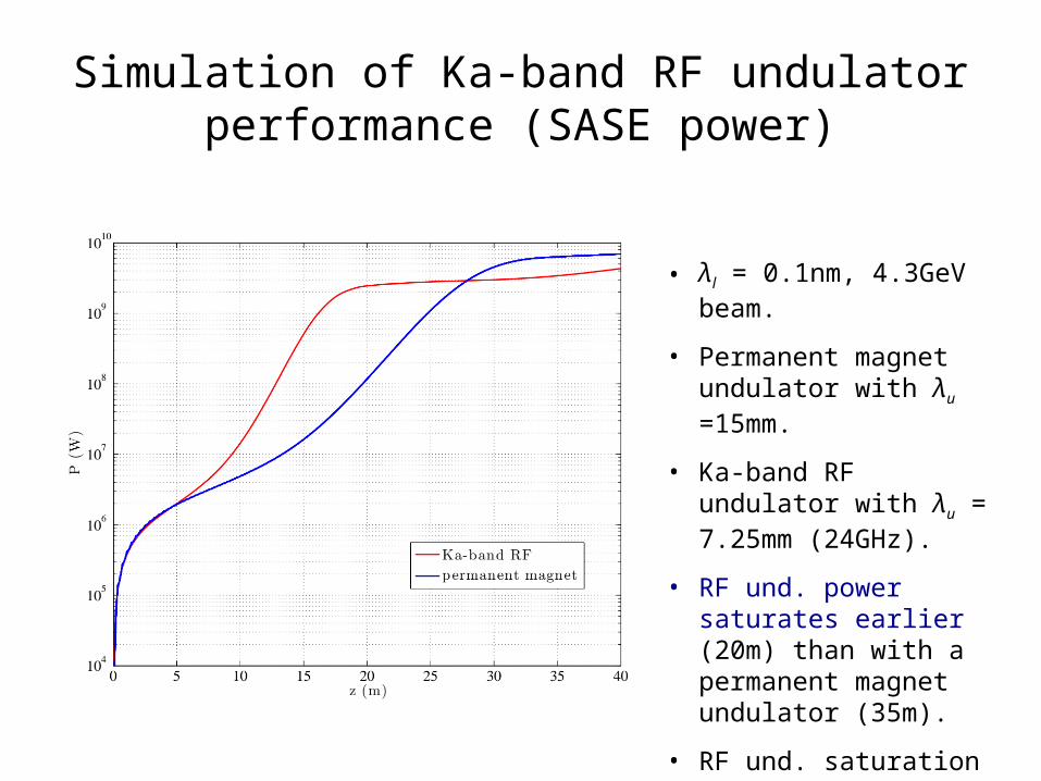
Simulation of Ka-band RF undulator performance (SASE power)
• λl = 0.1nm, 4.3GeV beam.
• Permanent magnet undulator with λu =15mm.
• Ka-band RF undulator with λu = 7.25mm (24GHz).
• RF und. power saturates earlier (20m) than with a permanent magnet undulator (35m).
• RF und. saturation power is about a factor 2 lower.
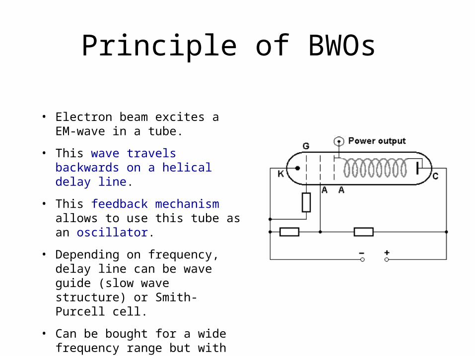
Principle of BWOs
• Electron beam excites a EM-wave in a tube.
• This wave travels backwards on a helical delay line.
• This feedback mechanism allows to use this tube as an oscillator.
• Depending on frequency, delay line can be wave guide (slow wave structure) or Smith-Purcell cell.
• Can be bought for a wide frequency range but with low power.

Status of BWOs for RF undulators
• Use as RF undulator source: use BWO in special transient mode to create higher power (super-radiant).
• An experiment has been performed at Ka-band: f = 30 GHz, P = 1 GHz, 200 ps.
• A special accelerator is used to create e--beam (RADAN-303BP).
• Phase and amplitude stability are not mentioned.
• Far from commercial product.
Institute of High Current Electronics, Tomsk (Russia), S.D. Korovin et al. Simulation (above) and measurement
(below) (about 40 GHz).
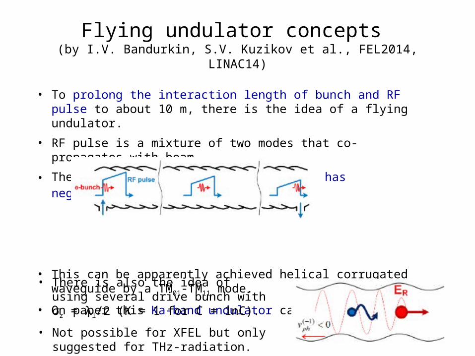
• To prolong the interaction length of bunch and RF pulse to about 10 m, there is the idea of a flying undulator.
• RF pulse is a mixture of two modes that co-propagates with beam.
• The vg is positive but the second mode has negative vph.
• This can be apparently achieved helical corrugated waveguide by a TM01-TM11 mode.
• On paper this Ka-band undulator can reach K = 0.2.
Flying undulator concepts (by I.V. Bandurkin, S.V. Kuzikov et al., FEL2014, LINAC14)
• There is also the idea of using several drive bunch with σz = λl/2 (K = 1 for C = 1nC).
• Not possible for XFEL but only suggested for THz-radiation.
3. Permanent magnet vs. RF undulator
Evaluation of RF undulators with respect to the XbFEL project.
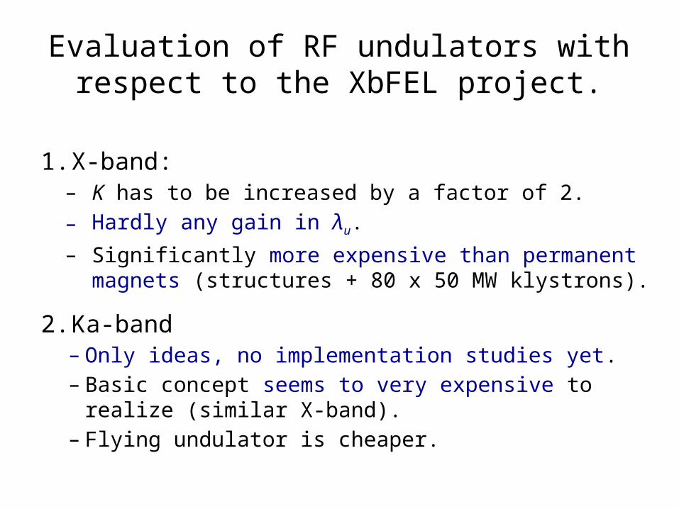
1. X-band:– K has to be increased by a factor of 2. – Hardly any gain in λu.– Significantly more expensive than permanent magnets
(structures + 80 x 50 MW klystrons).
2. Ka-band – Only ideas, no implementation studies yet.– Basic concept seems to very expensive to realize (similar X-
band).– Flying undulator is cheaper.
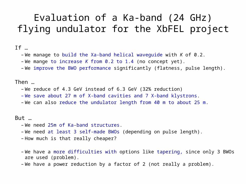
Evaluation of a Ka-band (24 GHz) flying undulator for the XbFEL project
If …– We manage to build the Xa-band helical waveguide with K of 0.2.– We mange to increase K from 0.2 to 1.4 (no concept yet).– We improve the BWO performance significantly (flatness, pulse length).
Then … – We reduce of 4.3 GeV instead of 6.3 GeV (32% reduction) – We save about 27 m of X-band cavities and 7 X-band klystrons. – We can also reduce the undulator length from 40 m to about 25 m.
But …– We need 25m of Ka-band structures.– We need at least 3 self-made BWOs (depending on pulse length).– How much is that really cheaper?
– We have a more difficulties with options like tapering, since only 3 BWOs are used (problem).– We have a power reduction by a factor of 2 (not really a problem).
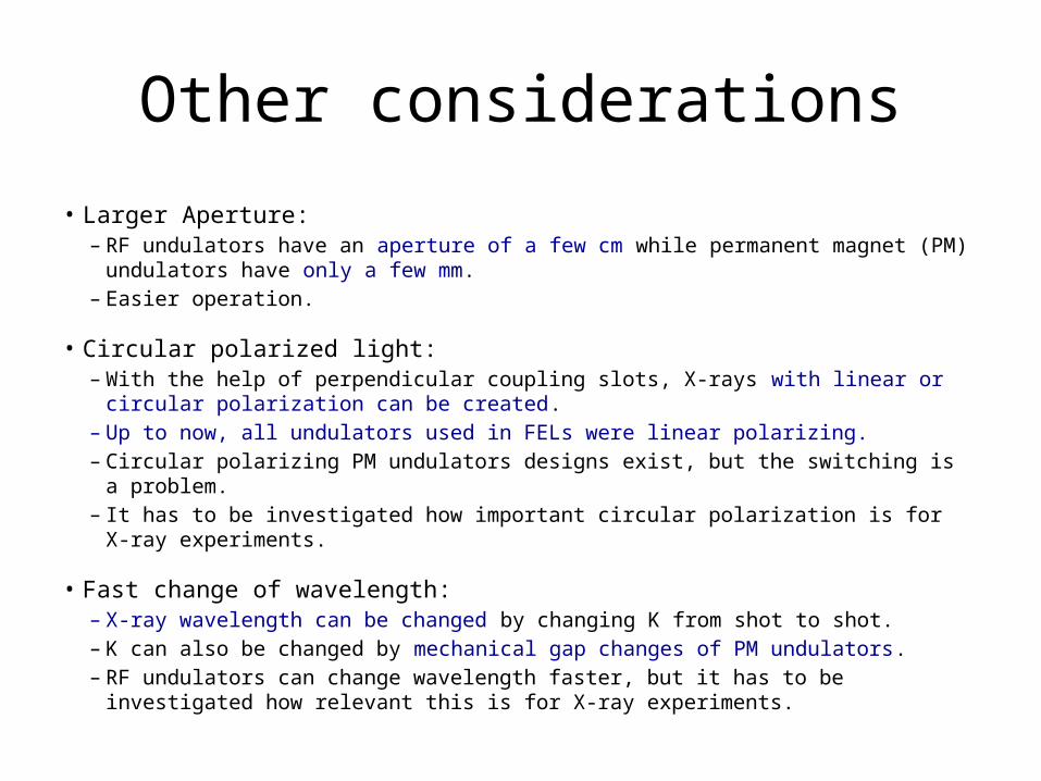
Other considerations
• Larger Aperture:– RF undulators have an aperture of a few cm while permanent magnet (PM) undulators
have only a few mm.– Easier operation.
• Circular polarized light:– With the help of perpendicular coupling slots, X-rays with linear or circular polarization
can be created.– Up to now, all undulators used in FELs were linear polarizing.– Circular polarizing PM undulators designs exist, but the switching is a problem.– It has to be investigated how important circular polarization is for X-ray experiments.
• Fast change of wavelength:– X-ray wavelength can be changed by changing K from shot to shot. – K can also be changed by mechanical gap changes of PM undulators. – RF undulators can change wavelength faster, but it has to be investigated how relevant
this is for X-ray experiments.
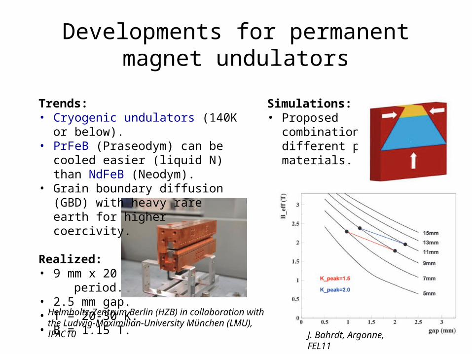
Developments for permanent magnet undulators
Trends: • Cryogenic undulators (140K or below).• PrFeB (Praseodym) can be cooled
easier (liquid N) than NdFeB (Neodym).• Grain boundary diffusion (GBD) with
heavy rare earth for higher coercivity.
Realized:• 9 mm x 20 period.• 2.5 mm gap. • T = 20-30 K.• B = 1.15 T.
Helmholtz-Zentrum Berlin (HZB) in collaboration with the Ludwig-Maximilian-University München (LMU), IPAC10
Simulations:• Proposed
combination of different pole materials.
J. Bahrdt, Argonne, FEL11
Conclusions• X-band RF undulator:
– Offers hardly any advantages compared to permanent magnet undulator– Power loss is prohibitive (about 80 klystrons necessary).
• Ka-band RF undulator: – Allows to use 1/3 less beam energy and shorter undulators.– Overall cost reduction is still questionable. – Also, there is no concept for a cavity with high enough K. – And the sources (transient mode BWOs) have to be improved and are far
from a commercial product.
• Permanent magnet undulator:– Prototypes with λu = 9 mm exist. – But cryogenics has to be foreseen.

Many thanks for your attention!