introduction to qzss, gnss positioning methods and low
TRANSCRIPT
Slide : 1Dinesh Manandhar, CSIS, The University of Tokyo, [email protected]
Introduction to QZSS, GNSS Positioning Methods and
Low-Cost Receiver Systems
Faculty Development Program (FDP) on GNSS/ NavIC and Applications21 – 25 September 2021
Dinesh Manandhar, Associate Professor (Project)
Center for Spatial Information Science (CSIS), The University of Tokyo
22nd September 2021
2021/09/22 9:16 PM

Slide : 2Dinesh Manandhar, CSIS, The University of Tokyo, [email protected]
QZSS (Quasi-Zenith Satellite System) “MICHIBIKI” Introduction
2021/09/22 9:16 PM
Image: MGA 2019, Mitsubishi

Slide : 3Dinesh Manandhar, CSIS, The University of Tokyo, [email protected]
QZSS Introduction
• The first QZSS satellite was launched in September 2010.
• Today, there are four satellites in the space.
• QZSS orbit is designed so that it can provide good position data even in highly dense urban area like Tokyo.
• It is designed interoperable with GPS satellites.
• QZSS provides unique new services such as MADOCA, CLAS and DCR.
• QZSS was declared operational in November 2018.
• The future constellation of QZSS will have 7 satellites.
• QZSS Information Links: • https://qzss.go.jp/en/overview/downloads/movie_qzss.html• https://qzss.go.jp/en/
2021/09/22 9:16 PM

Slide : 4Dinesh Manandhar, CSIS, The University of Tokyo, [email protected]
QZSS was Declared Operational on 1st NOV 2018
Declaration Ceremony of QZSS Operationhttp://qzss.go.jp/events/ceremony_181105.html
Slide : 5Dinesh Manandhar, CSIS, The University of Tokyo, [email protected]
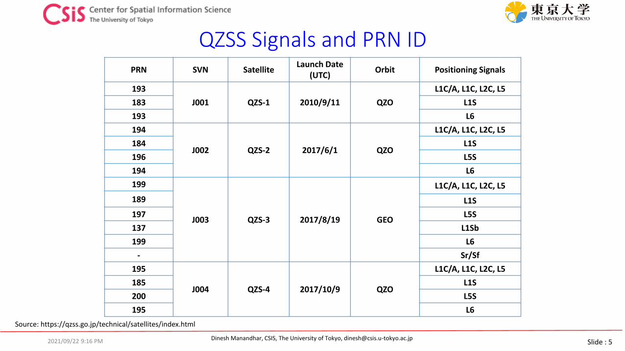
QZSS Signals and PRN ID
2021/09/22 9:16 PM
PRN SVN SatelliteLaunch Date
(UTC)Orbit Positioning Signals
193
J001 QZS-1 2010/9/11 QZO
L1C/A, L1C, L2C, L5
183 L1S
193 L6
194
J002 QZS-2 2017/6/1 QZO
L1C/A, L1C, L2C, L5
184 L1S
196 L5S
194 L6
199
J003 QZS-3 2017/8/19 GEO
L1C/A, L1C, L2C, L5
189 L1S
197 L5S
137 L1Sb
199 L6
- Sr/Sf
195
J004 QZS-4 2017/10/9 QZO
L1C/A, L1C, L2C, L5
185 L1S
200 L5S
195 L6
Source: https://qzss.go.jp/technical/satellites/index.html
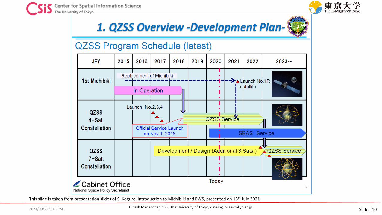
Slide : 6Dinesh Manandhar, CSIS, The University of Tokyo, [email protected]
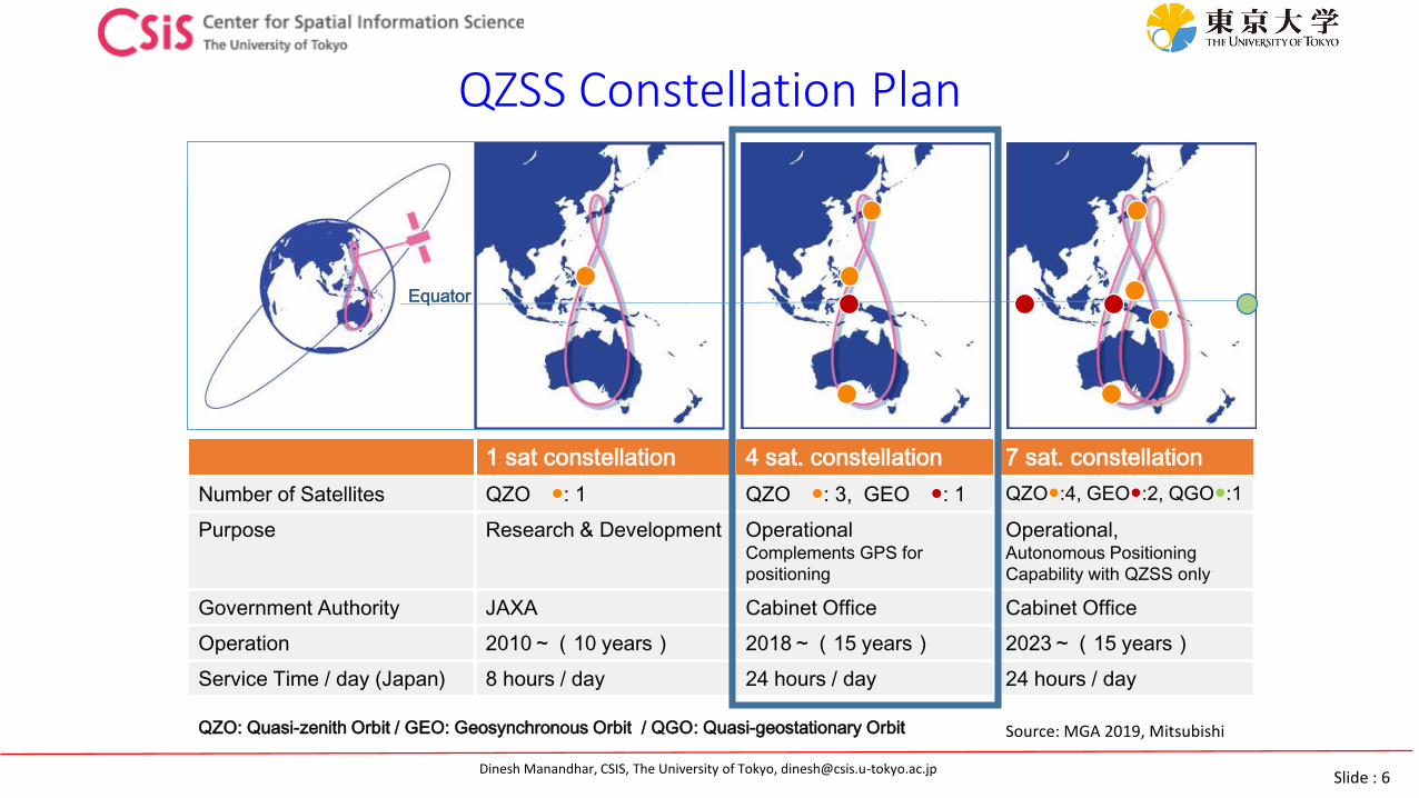
QZSS Constellation Plan
Equator
1 sat constellation 4 sat. constellation 7 sat. constellation
Number of Satellites QZO ●: 1 QZO ●: 3, GEO ●: 1 QZO●:4, GEO●:2, QGO●:1
Purpose Research & Development OperationalComplements GPS for
positioning
Operational,Autonomous Positioning
Capability with QZSS only
Government Authority JAXA Cabinet Office Cabinet Office
Operation 2010~(10 years) 2018~(15 years) 2023~(15 years)
Service Time / day (Japan) 8 hours / day 24 hours / day 24 hours / day
QZO: Quasi-zenith Orbit / GEO: Geosynchronous Orbit / QGO: Quasi-geostationary Orbit Source: MGA 2019, Mitsubishi
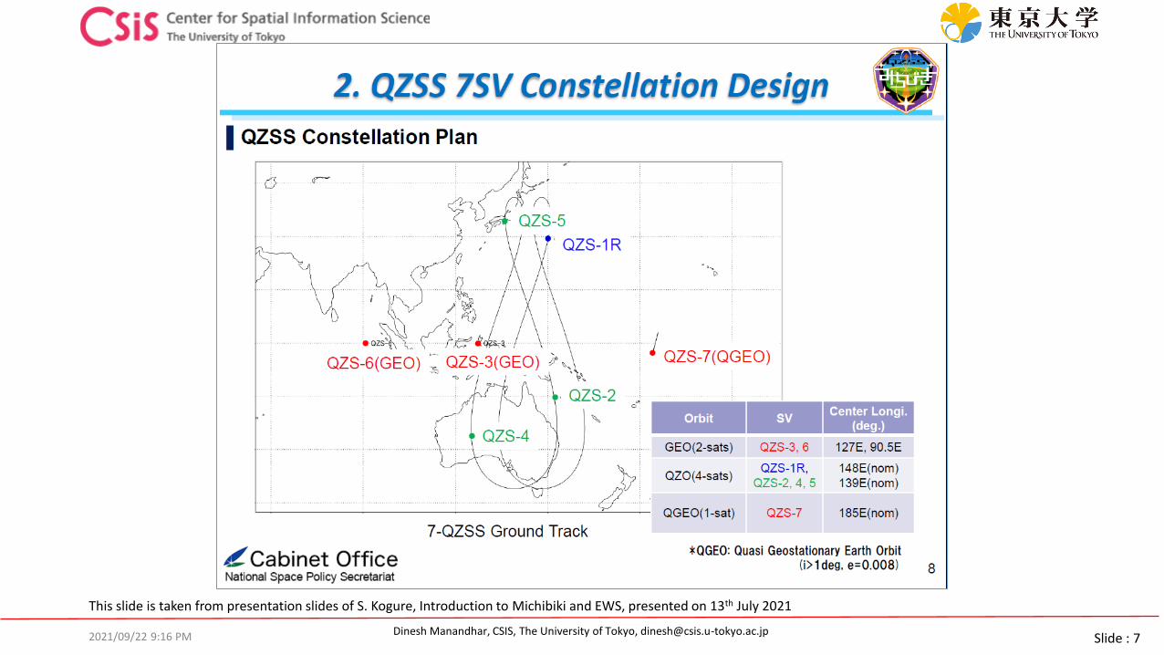
Slide : 7Dinesh Manandhar, CSIS, The University of Tokyo, [email protected]/09/22 9:16 PM
This slide is taken from presentation slides of S. Kogure, Introduction to Michibiki and EWS, presented on 13th July 2021

Slide : 8Dinesh Manandhar, CSIS, The University of Tokyo, [email protected]
Characteristics of QZSS• QZSS signal is designed in such a way that it is interoperable with GPS• QZSS is visible near zenith; improves visibility & DOP in dense urban area• Provides Orbit Data of other GNSS signals• Provides Augmentation Data for Sub-meter and Centimeter level position accuracy• Provides Messaging System during Disasters
http://qzss.go.jp/en/overview/services/sv04_pnt.html
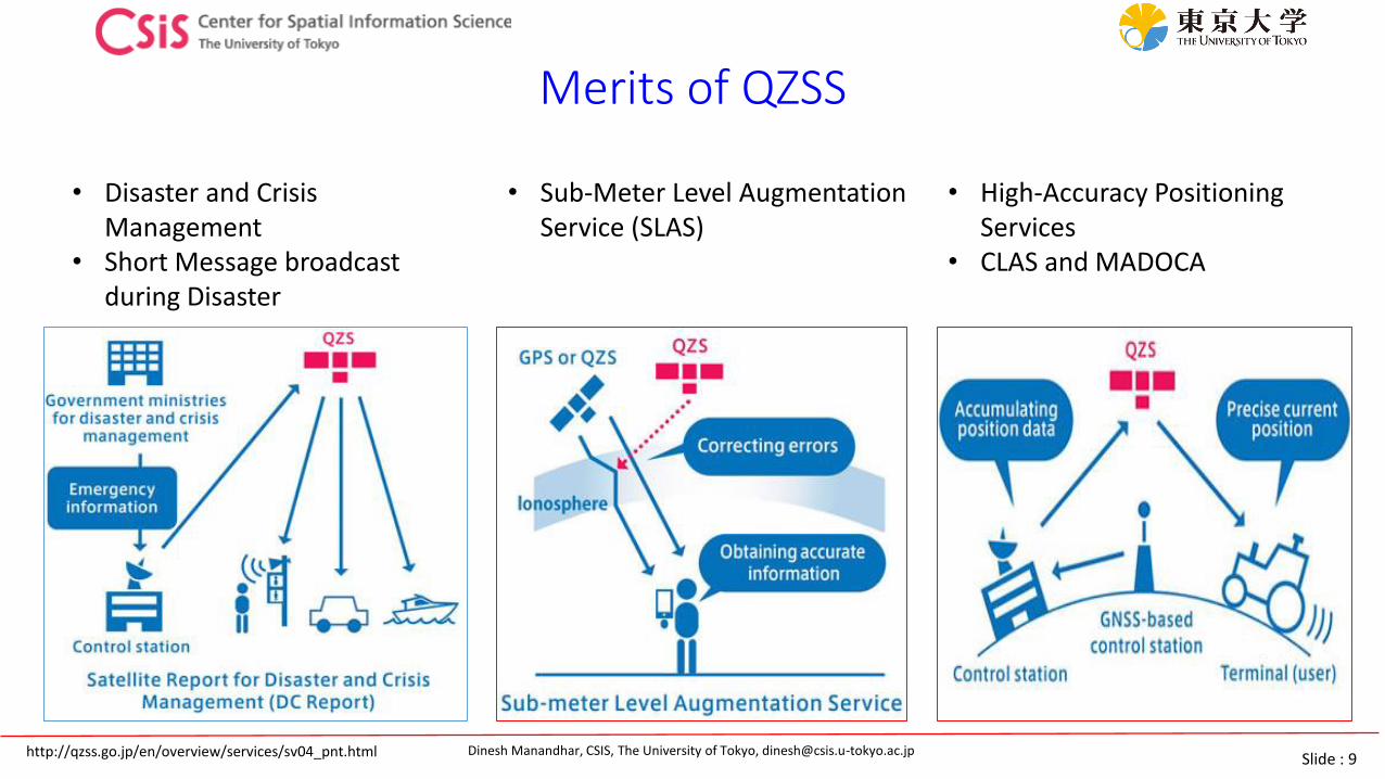
Slide : 9Dinesh Manandhar, CSIS, The University of Tokyo, [email protected]
Merits of QZSS
• Sub-Meter Level Augmentation Service (SLAS)
• Disaster and Crisis Management
• Short Message broadcast during Disaster
• High-Accuracy Positioning Services
• CLAS and MADOCA
http://qzss.go.jp/en/overview/services/sv04_pnt.html
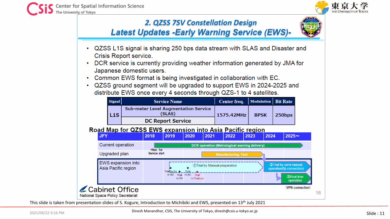
Slide : 10Dinesh Manandhar, CSIS, The University of Tokyo, [email protected]/09/22 9:16 PM
This slide is taken from presentation slides of S. Kogure, Introduction to Michibiki and EWS, presented on 13th July 2021
Slide : 11Dinesh Manandhar, CSIS, The University of Tokyo, [email protected]/09/22 9:16 PM
This slide is taken from presentation slides of S. Kogure, Introduction to Michibiki and EWS, presented on 13th July 2021

Slide : 12Dinesh Manandhar, CSIS, The University of Tokyo, [email protected]
How does a GPS/GNSS Receiver Work?
2021/09/22 9:16 PM

Slide : 13Dinesh Manandhar, CSIS, The University of Tokyo, [email protected]
GNSS: How does it work? Determine the Distance using Radio Wave
0ms
25ms
50ms0ms
25ms
50ms
75ms
Assume that the Satellite Transmits Signal at 0ms.
If Receiver receives the same Signal after 67ms, Distance = 67x300,000 = 20,100Km
Distance = (Reception Time - Transmission time) × Speed of light
Speed of Light: 300,000 km/s
Satellite with a known position transmits a regular time signal.
2021/09/22 9:16 PM
Slide : 14Dinesh Manandhar, CSIS, The University of Tokyo, [email protected]
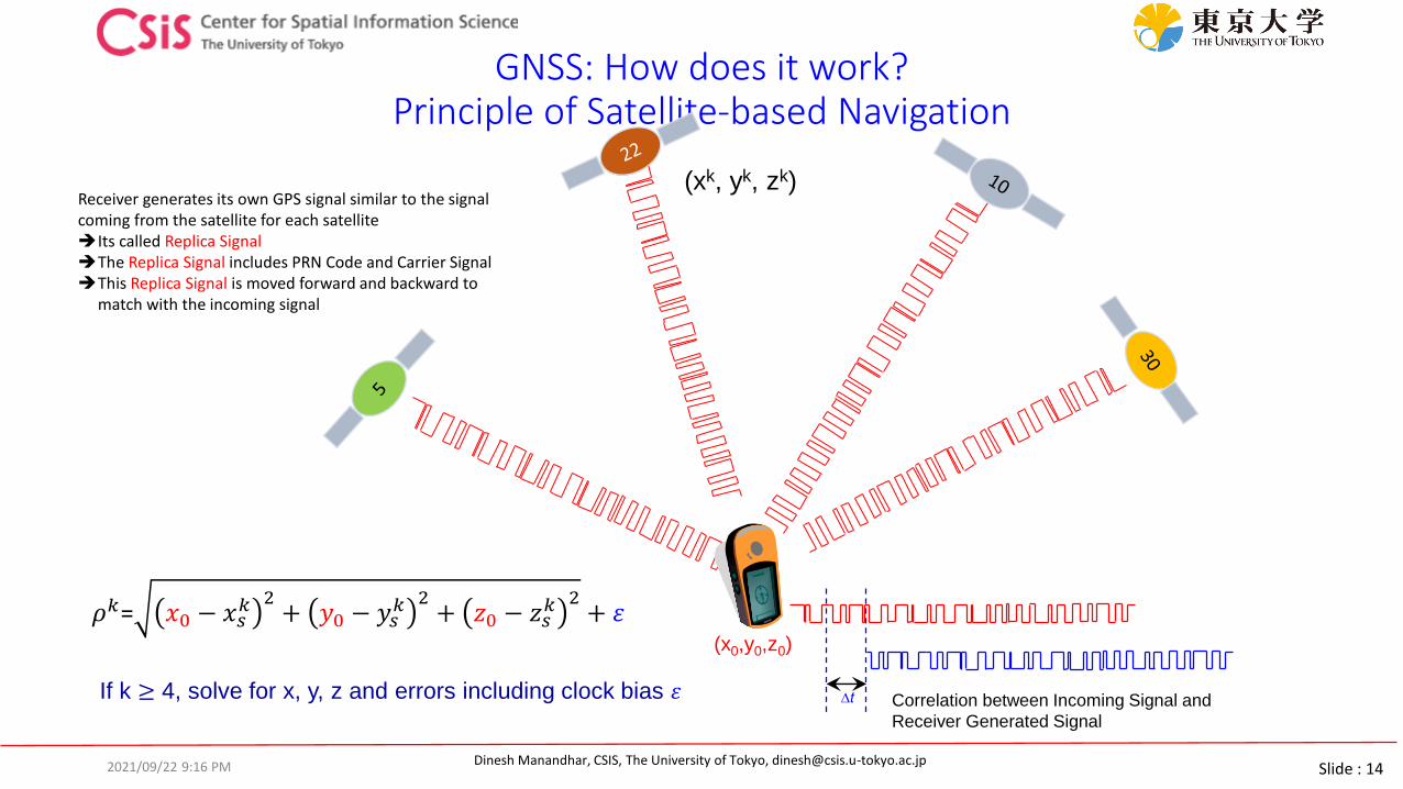
GNSS: How does it work? Principle of Satellite-based Navigation
Correlation between Incoming Signal and
Receiver Generated Signal
If k ≥ 4, solve for x, y, z and errors including clock bias 휀
(x0,y0,z0)
(xk, yk, zk)
∆t
Receiver generates its own GPS signal similar to the signal coming from the satellite for each satelliteIts called Replica SignalThe Replica Signal includes PRN Code and Carrier SignalThis Replica Signal is moved forward and backward to
match with the incoming signal
2021/09/22 9:16 PM
𝜌𝑘= 𝑥0 − 𝑥𝑠𝑘 2
+ 𝑦0 − 𝑦𝑠𝑘 2
+ 𝑧0 − 𝑧𝑠𝑘 2
+ 휀
Slide : 15Dinesh Manandhar, CSIS, The University of Tokyo, [email protected]
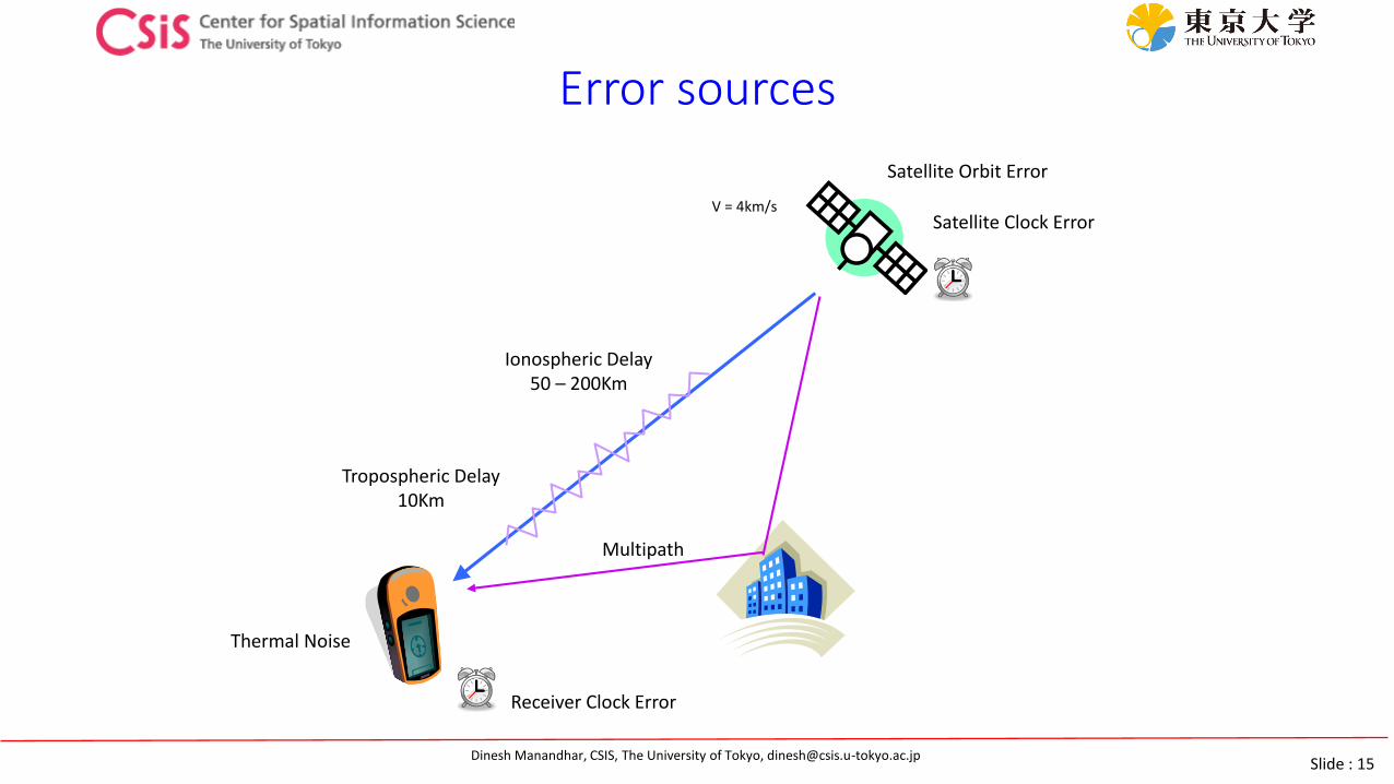
Error sources
Thermal Noise
Satellite Orbit Error
Satellite Clock ErrorV = 4km/s
Ionospheric Delay50 – 200Km
Tropospheric Delay10Km
Receiver Clock Error
Multipath
Slide : 16Dinesh Manandhar, CSIS, The University of Tokyo, [email protected]
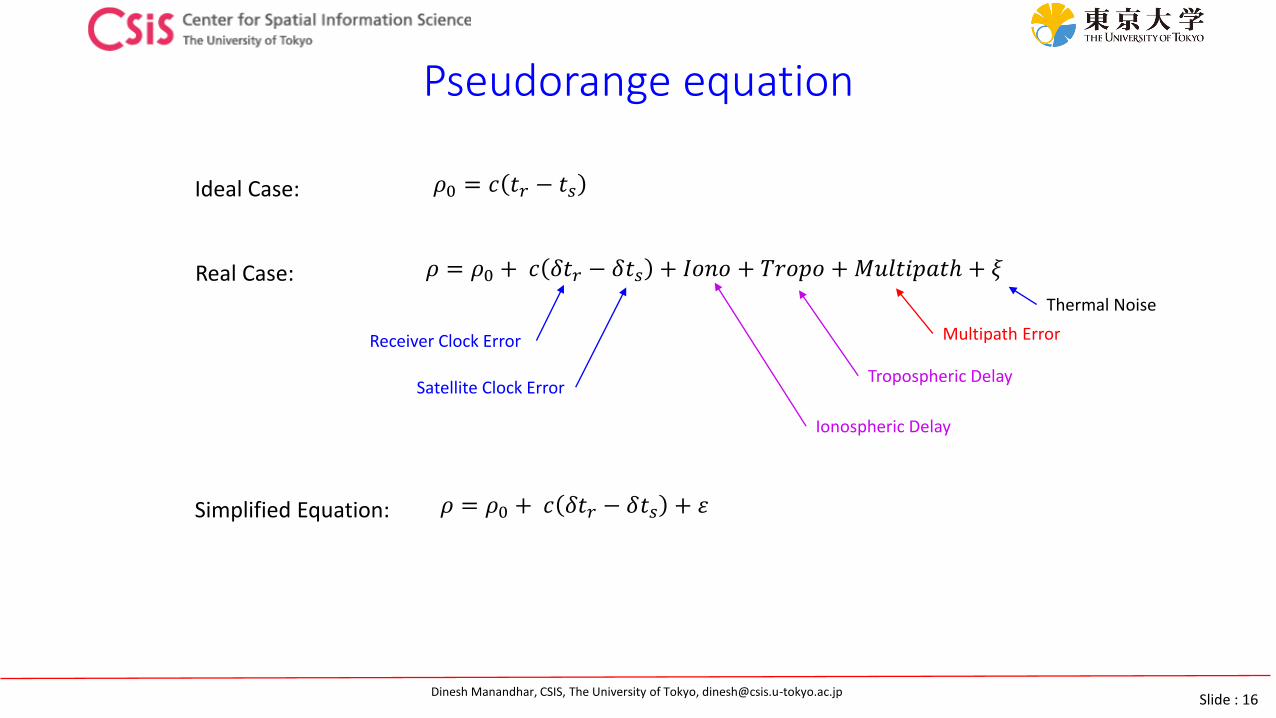
Pseudorange equation
𝜌0 = 𝑐 𝑡𝑟 − 𝑡𝑠
𝜌 = 𝜌0 + 𝑐 𝛿𝑡𝑟 − 𝛿𝑡𝑠 + 𝐼𝑜𝑛𝑜 + 𝑇𝑟𝑜𝑝𝑜 + 𝑀𝑢𝑙𝑡𝑖𝑝𝑎𝑡ℎ + 𝜉
𝜌 = 𝜌0 + 𝑐 𝛿𝑡𝑟 − 𝛿𝑡𝑠 + 휀
Receiver Clock Error
Satellite Clock Error
Ionospheric Delay
Tropospheric Delay
Multipath Error
Thermal Noise
Ideal Case:
Real Case:
Simplified Equation:

Slide : 17Dinesh Manandhar, CSIS, The University of Tokyo, [email protected]
Pseudorange model
𝜌= 𝑥 − 𝑥𝑠2 + 𝑦 − 𝑦𝑠
2 + 𝑧 − 𝑧𝑠2 + 𝑐 𝛿𝑡𝑟 − 𝛿𝑡𝑠 + 휀
Where: x, y, z : Unknown receiver positiondelta tr: Unknown receiver clock errorepsilon : minimize this error by finding an optimal solution
In order to solve the above equations, we need “n” simultaneous nonlinear equations from “n” pseudorange observations.
We need at least 4 independent observations in order to determine 4 unknown parameters, x, y, z and receiver clock error.
𝑥, 𝑦, 𝑧
𝑥𝑠, 𝑦𝑠, 𝑧𝑠Satellite
Receiver
𝜌0 𝜌0
Range between satellite and receiver

Slide : 18Dinesh Manandhar, CSIS, The University of Tokyo, [email protected]
GPS L1C/A Signal Structure (Satellite Side)
L1 Carrier, 1575.42Mhz
Carrier Signal
x154
900 Phase Reverse
L1 Band GPS Signal
∑
Navigation Data, 50Hz
Navigation Data
x1/204600
PRN Code, 1.023Mhz
PRN Code
x1/10X1, Clock
10.23Mhz
Atomic ClockRb or Cs Clocks
2021/09/22 9:16 PM

Slide : 19Dinesh Manandhar, CSIS, The University of Tokyo, [email protected]
GPS L1C/A Signal Structure
• Carrier Signal• It defines the frequency of the signal• For example:
• GPS L1 is 1575.42MHz, L2 is 1227.60MHz and L5 is 1176.45MHz
• PRN Code• Necessary to modulate carrier signal• Used to identify satellite ID in the signal• Should have good auto-correlation and cross-correlation properties
• Navigation Data• Includes satellite orbit related data (ephemeris and almanac data)• Includes satellite clock related information (clock errors etc.)• Includes satellite health information
2021/09/22 9:16 PM

Slide : 20Dinesh Manandhar, CSIS, The University of Tokyo, [email protected]
Block Diagram of GPS Receiver
2021/09/22 9:16 PM
Pre-AmpLNA
Frequency Generator
Oscillator(Clock)
Down Converter A/D Converter
AGC
Position Output
GPS Antenna
Acquisition
Navigation Data
Tracking
Replica Signal Generator
Slide : 21Dinesh Manandhar, CSIS, The University of Tokyo, [email protected]
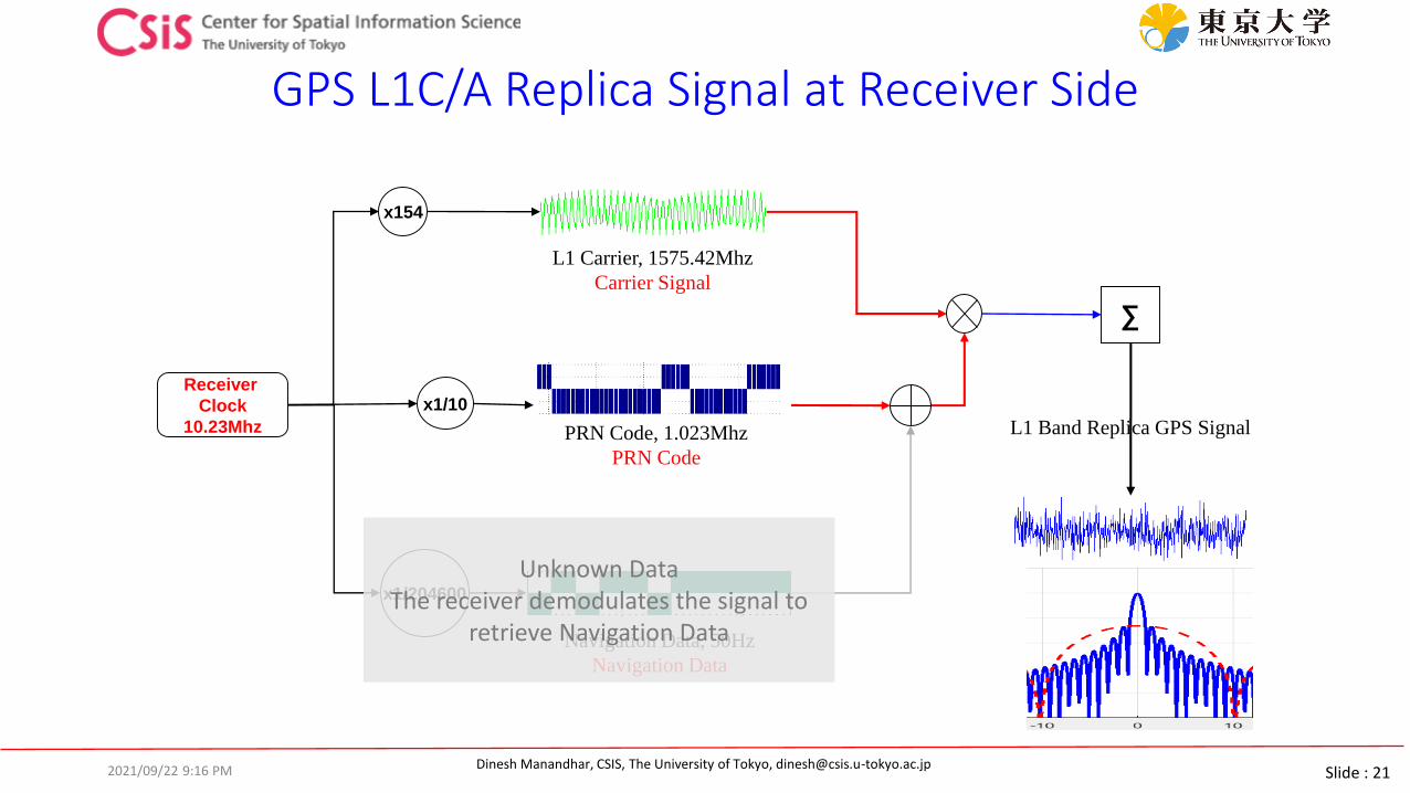
GPS L1C/A Replica Signal at Receiver Side
L1 Carrier, 1575.42Mhz
Carrier Signal
x154
L1 Band Replica GPS Signal
∑
PRN Code, 1.023Mhz
PRN Code
x1/10Receiver
Clock
10.23Mhz
2021/09/22 9:16 PM
Navigation Data, 50Hz
Navigation Data
x1/204600
Unknown DataThe receiver demodulates the signal to
retrieve Navigation Data
Slide : 22Dinesh Manandhar, CSIS, The University of Tokyo, [email protected]
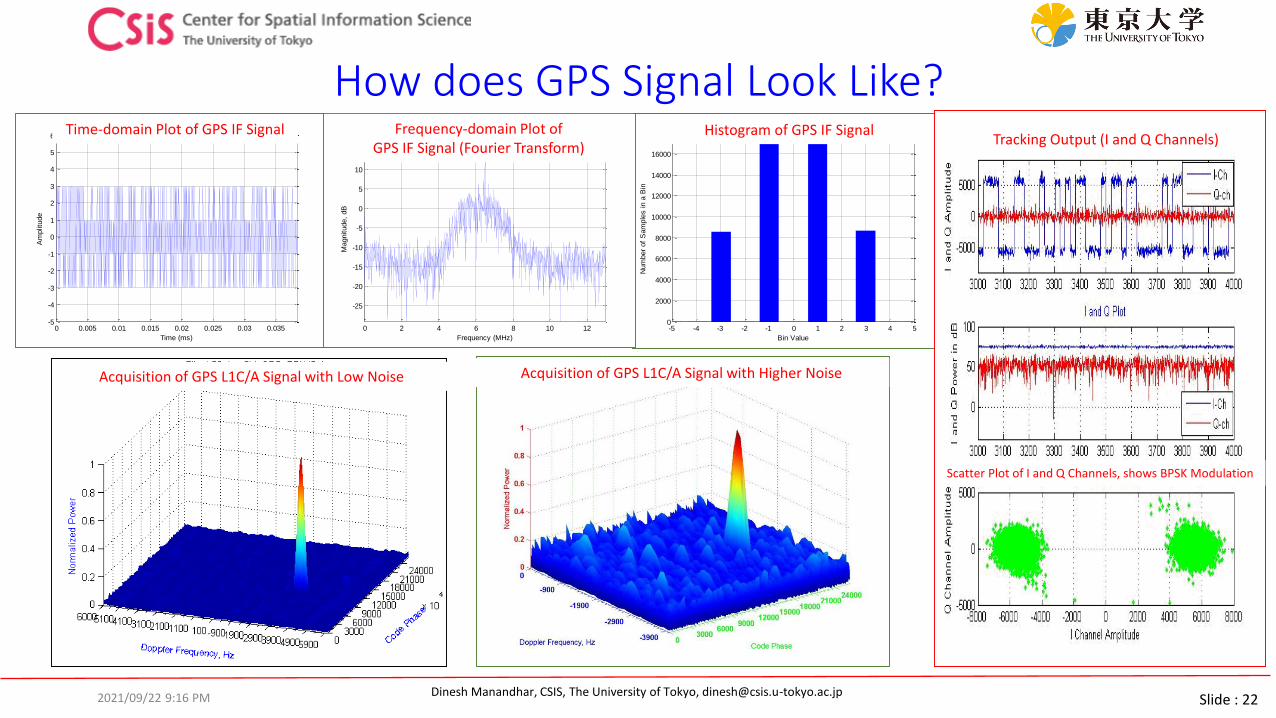
How does GPS Signal Look Like?
0 0.005 0.01 0.015 0.02 0.025 0.03 0.035-5
-4
-3
-2
-1
0
1
2
3
4
5
6
Time Domain Plot of IF Data
File: JAX_LIV.dat
Time (ms)
Am
plit
ude
Time-domain Plot of GPS IF Signal
-5 -4 -3 -2 -1 0 1 2 3 4 50
2000
4000
6000
8000
10000
12000
14000
16000
Histogram of IF Data
File: JAX_LIV.dat
Bin Value
Num
ber
of
Sam
ple
s in a
Bin
Histogram of GPS IF Signal
0 2 4 6 8 10 12
-25
-20
-15
-10
-5
0
5
10
15
Frequency (MHz)M
agnitude,
dB
Frequency Domain Plot of IF Data
File: JAX_LIV.datFrequency-domain Plot of GPS IF Signal (Fourier Transform)
Acquisition of GPS L1C/A Signal with Low Noise Acquisition of GPS L1C/A Signal with Higher Noise
Tracking Output (I and Q Channels)
Scatter Plot of I and Q Channels, shows BPSK Modulation
2021/09/22 9:16 PM
Slide : 23Dinesh Manandhar, CSIS, The University of Tokyo, [email protected]
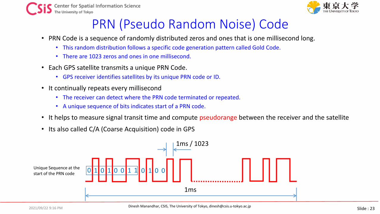
PRN (Pseudo Random Noise) Code• PRN Code is a sequence of randomly distributed zeros and ones that is one millisecond long.
• This random distribution follows a specific code generation pattern called Gold Code.
• There are 1023 zeros and ones in one millisecond.
• Each GPS satellite transmits a unique PRN Code.
• GPS receiver identifies satellites by its unique PRN code or ID.
• It continually repeats every millisecond
• The receiver can detect where the PRN code terminated or repeated.
• A unique sequence of bits indicates start of a PRN code.
• It helps to measure signal transit time and compute pseudorange between the receiver and the satellite
• Its also called C/A (Coarse Acquisition) code in GPS
1ms / 1023
1ms
01 1 1 10 0 0 1 0 00Unique Sequence at the start of the PRN code
2021/09/22 9:16 PM

Slide : 24Dinesh Manandhar, CSIS, The University of Tokyo, [email protected]
Pseudorange (Code-Phase Measurement) - 1
Transit time
About 20,000 km
Transmission Time
Reception Time
Signal propagation at the speed of light
A GPS receiver measures the signal transmission time from the code phase at signal reception time.
Pseudorange = (Reception Time – Transmission time) x Speed of Light
2021/09/22 9:16 PM
Slide : 25Dinesh Manandhar, CSIS, The University of Tokyo, [email protected]
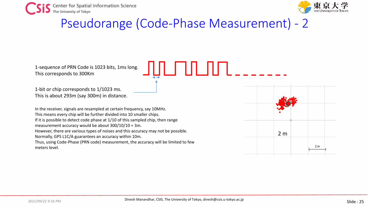
Pseudorange (Code-Phase Measurement) - 2
2 m
1-sequence of PRN Code is 1023 bits, 1ms long. This corresponds to 300Km
1-bit or chip corresponds to 1/1023 ms.This is about 293m (say 300m) in distance.
In the receiver, signals are resampled at certain frequency, say 10MHz. This means every chip will be further divided into 10 smaller chips. If it is possible to detect code phase at 1/10 of this sampled chip, then range measurement accuracy would be about 300/10/10 = 3m. However, there are various types of noises and this accuracy may not be possible. Normally, GPS L1C/A guarantees an accuracy within 10m. Thus, using Code-Phase (PRN code) measurement, the accuracy will be limited to few meters level.
2021/09/22 9:16 PM
Slide : 26Dinesh Manandhar, CSIS, The University of Tokyo, [email protected]
Carrier-Phase Measurement – 1
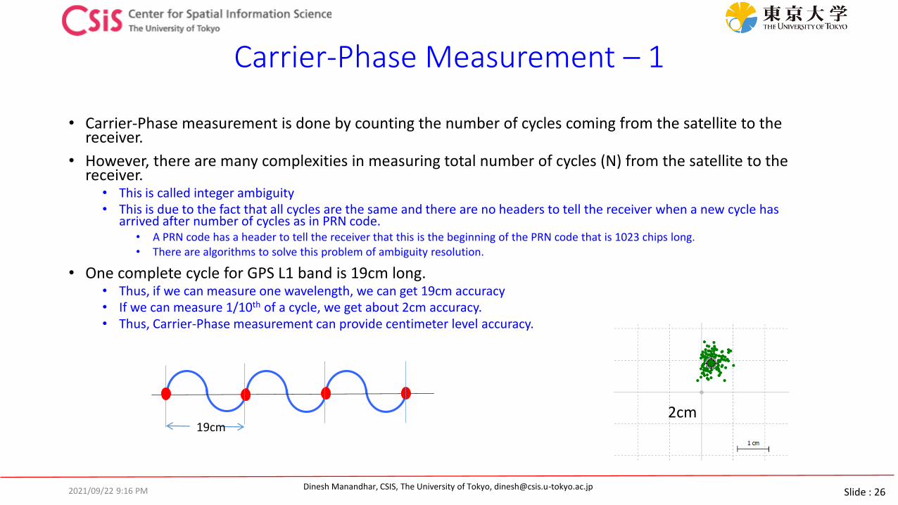
• Carrier-Phase measurement is done by counting the number of cycles coming from the satellite to the receiver.
• However, there are many complexities in measuring total number of cycles (N) from the satellite to the receiver.
• This is called integer ambiguity• This is due to the fact that all cycles are the same and there are no headers to tell the receiver when a new cycle has
arrived after number of cycles as in PRN code. • A PRN code has a header to tell the receiver that this is the beginning of the PRN code that is 1023 chips long. • There are algorithms to solve this problem of ambiguity resolution.
• One complete cycle for GPS L1 band is 19cm long. • Thus, if we can measure one wavelength, we can get 19cm accuracy• If we can measure 1/10th of a cycle, we get about 2cm accuracy. • Thus, Carrier-Phase measurement can provide centimeter level accuracy.
19cm2cm
2021/09/22 9:16 PM
Slide : 27Dinesh Manandhar, CSIS, The University of Tokyo, [email protected]
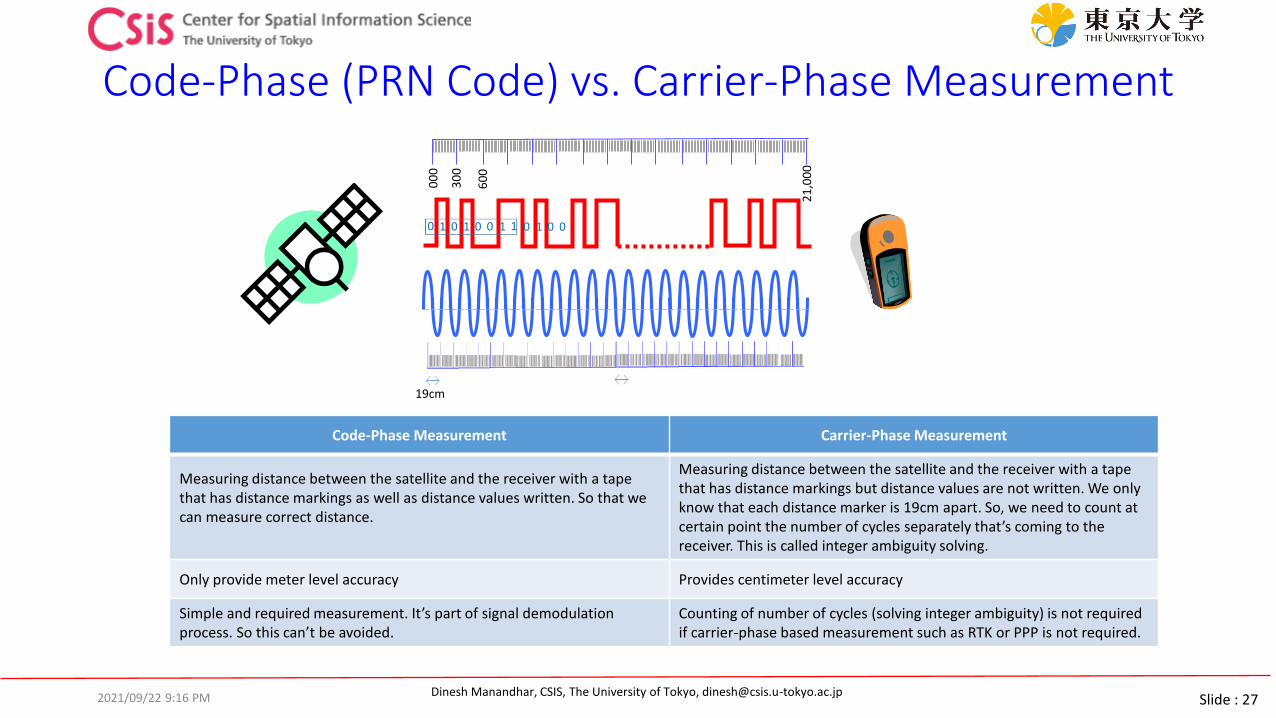
Code-Phase (PRN Code) vs. Carrier-Phase Measurement
00
0
30
0
60
0
21
,00
0
19cm
Code-Phase Measurement Carrier-Phase Measurement
Measuring distance between the satellite and the receiver with a tapethat has distance markings as well as distance values written. So that we can measure correct distance.
Measuring distance between the satellite and the receiver with a tapethat has distance markings but distance values are not written. We only know that each distance marker is 19cm apart. So, we need to count at certain point the number of cycles separately that’s coming to the receiver. This is called integer ambiguity solving.
Only provide meter level accuracy Provides centimeter level accuracy
Simple and required measurement. It’s part of signal demodulation process. So this can’t be avoided.
Counting of number of cycles (solving integer ambiguity) is not required if carrier-phase based measurement such as RTK or PPP is not required.
2021/09/22 9:16 PM
Slide : 28Dinesh Manandhar, CSIS, The University of Tokyo, [email protected]
How to Improve GPS Accuracy?
2021/09/22 9:16 PM
Slide : 29Dinesh Manandhar, CSIS, The University of Tokyo, [email protected]
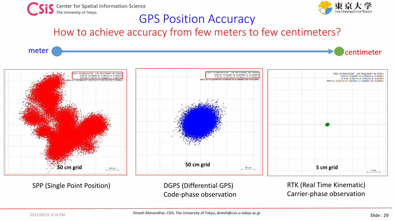
GPS Position AccuracyHow to achieve accuracy from few meters to few centimeters?
SPP (Single Point Position)
50 cm grid
RTK (Real Time Kinematic)Carrier-phase observation
5 cm grid
DGPS (Differential GPS)Code-phase observation
50 cm grid
meter centimeter
2021/09/22 9:16 PM

Slide : 30Dinesh Manandhar, CSIS, The University of Tokyo, [email protected]
Errors in GPS Observation (L1C/A Signal)
Error SourcesOne-Sigma Error , m
CommentsTotal DGPS
Satellite Orbit 2.0 0.0Common errors are removed
Satellite Clock 2.0 0.0
Ionosphere Error 4.0 0.4Common errors are reduced
Troposphere Error 0.7 0.2
Multipath 1.4 1.4
Receiver Circuits 0.5 0.5
If we can remove common errors, position accuracy can be increased. Common errors are: Satellite Orbit Errors, Satellite Clock Errors and Atmospheric Errors (within few km)
Values in the Table are just for illustrative purpose, not the exact measured values.
Table Source : http://www.edu-observatory.org/gps/gps_accuracy.html#Multipath
2021/09/22 9:16 PM

Slide : 31Dinesh Manandhar, CSIS, The University of Tokyo, [email protected]
How to Improve Accuracy?
• Both Code-Phase and Carrier-Phase observations are necessary• Carrier-phase provides centimeter level resolution
• Need to remove or minimize the following errors: • Satellite Related Error
• Satellite orbit errors• Satellite clock errors
• Space Related Errors• Ionospheric errors• Tropospheric erros
• Receiver Related Errors• Receiver clock error• Receiver circuit related
2021/09/22 9:16 PM
Slide : 32Dinesh Manandhar, CSIS, The University of Tokyo, [email protected]
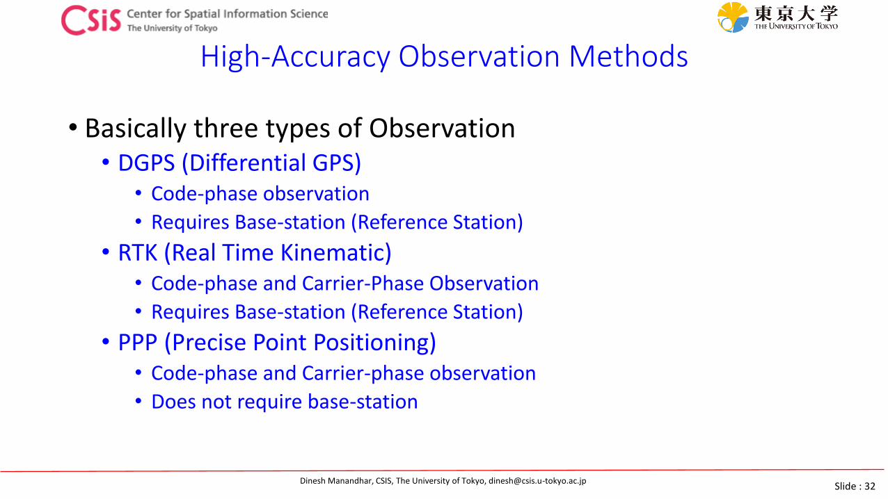
High-Accuracy Observation Methods
• Basically three types of Observation• DGPS (Differential GPS)
• Code-phase observation
• Requires Base-station (Reference Station)
• RTK (Real Time Kinematic)• Code-phase and Carrier-Phase Observation
• Requires Base-station (Reference Station)
• PPP (Precise Point Positioning)• Code-phase and Carrier-phase observation
• Does not require base-station
Slide : 33Dinesh Manandhar, CSIS, The University of Tokyo, [email protected]
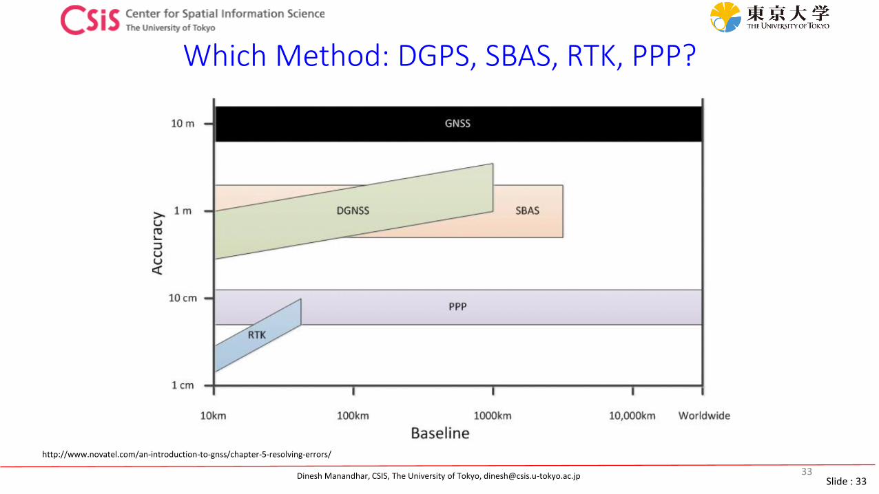
Which Method: DGPS, SBAS, RTK, PPP?
33
http://www.novatel.com/an-introduction-to-gnss/chapter-5-resolving-errors/
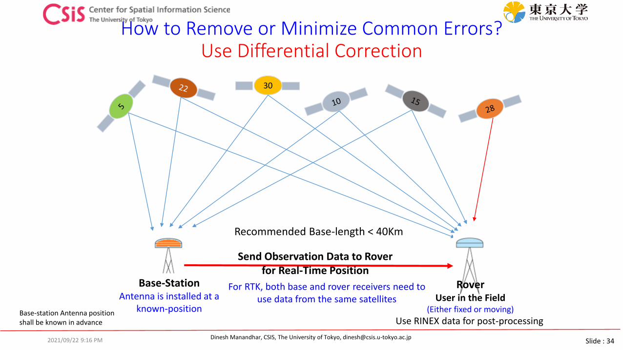
Slide : 34Dinesh Manandhar, CSIS, The University of Tokyo, [email protected]
How to Remove or Minimize Common Errors? Use Differential Correction
30
Send Observation Data to Rover for Real-Time Position
RoverUser in the Field
(Either fixed or moving)
Base-StationAntenna is installed at a
known-position
For RTK, both base and rover receivers need to use data from the same satellites
Base-station Antenna positionshall be known in advance Use RINEX data for post-processing
Recommended Base-length < 40Km
2021/09/22 9:16 PM
Slide : 35Dinesh Manandhar, CSIS, The University of Tokyo, [email protected]
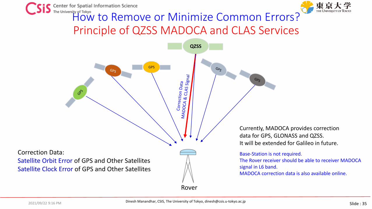
How to Remove or Minimize Common Errors? Principle of QZSS MADOCA and CLAS Services
GPS
Rover
QZSS
Correction Data: Satellite Orbit Error of GPS and Other SatellitesSatellite Clock Error of GPS and Other Satellites
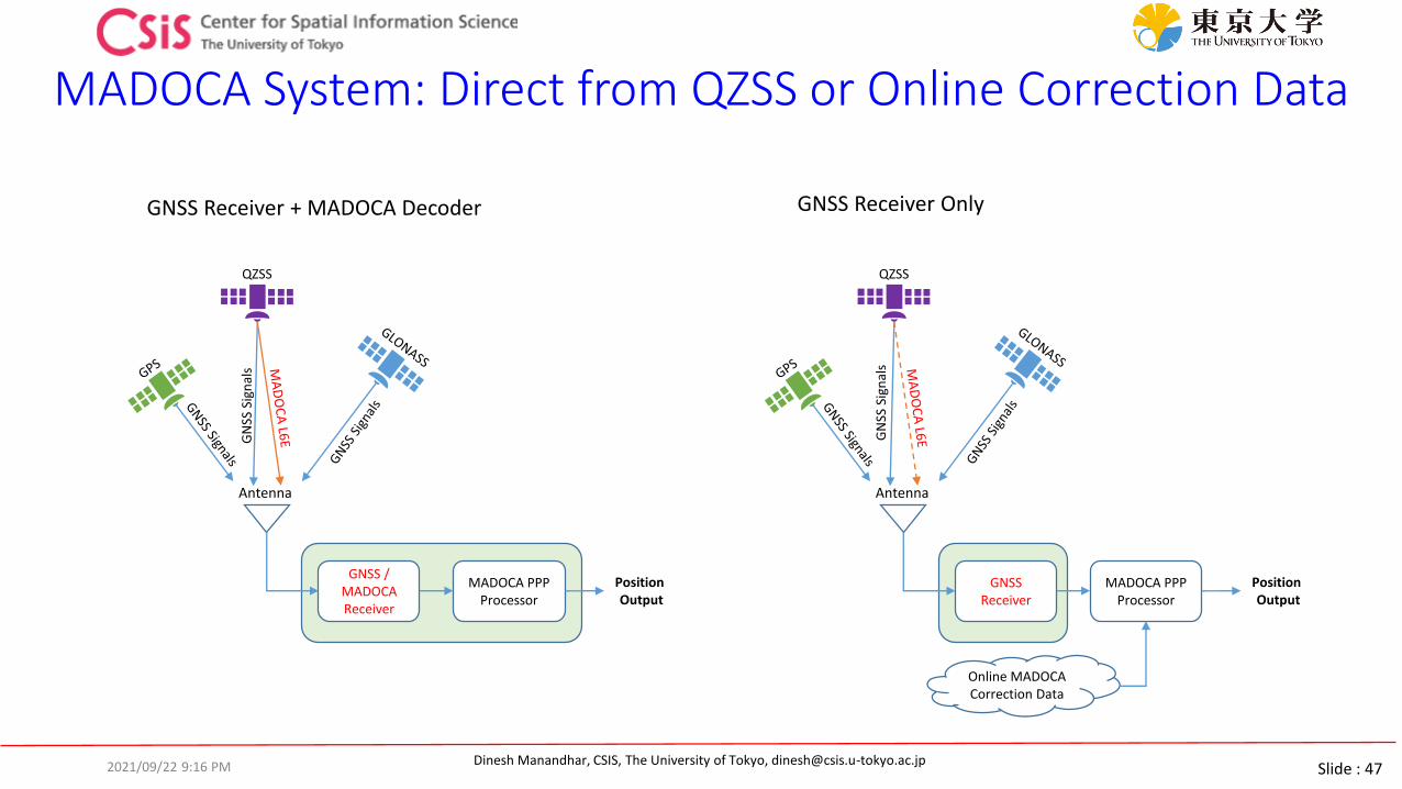
Currently, MADOCA provides correction data for GPS, GLONASS and QZSS. It will be extended for Galileo in future.
Base-Station is not required. The Rover receiver should be able to receiver MADOCA signal in L6 band. MADOCA correction data is also available online.
2021/09/22 9:16 PM

Slide : 36Dinesh Manandhar, CSIS, The University of Tokyo, [email protected]
Low-Cost High-Accuracy Receiver SystemsRTKDROID, MADROID, MAD-WIN, MAD-π
2021/09/22 9:16 PM
Slide : 37Dinesh Manandhar, CSIS, The University of Tokyo, [email protected]
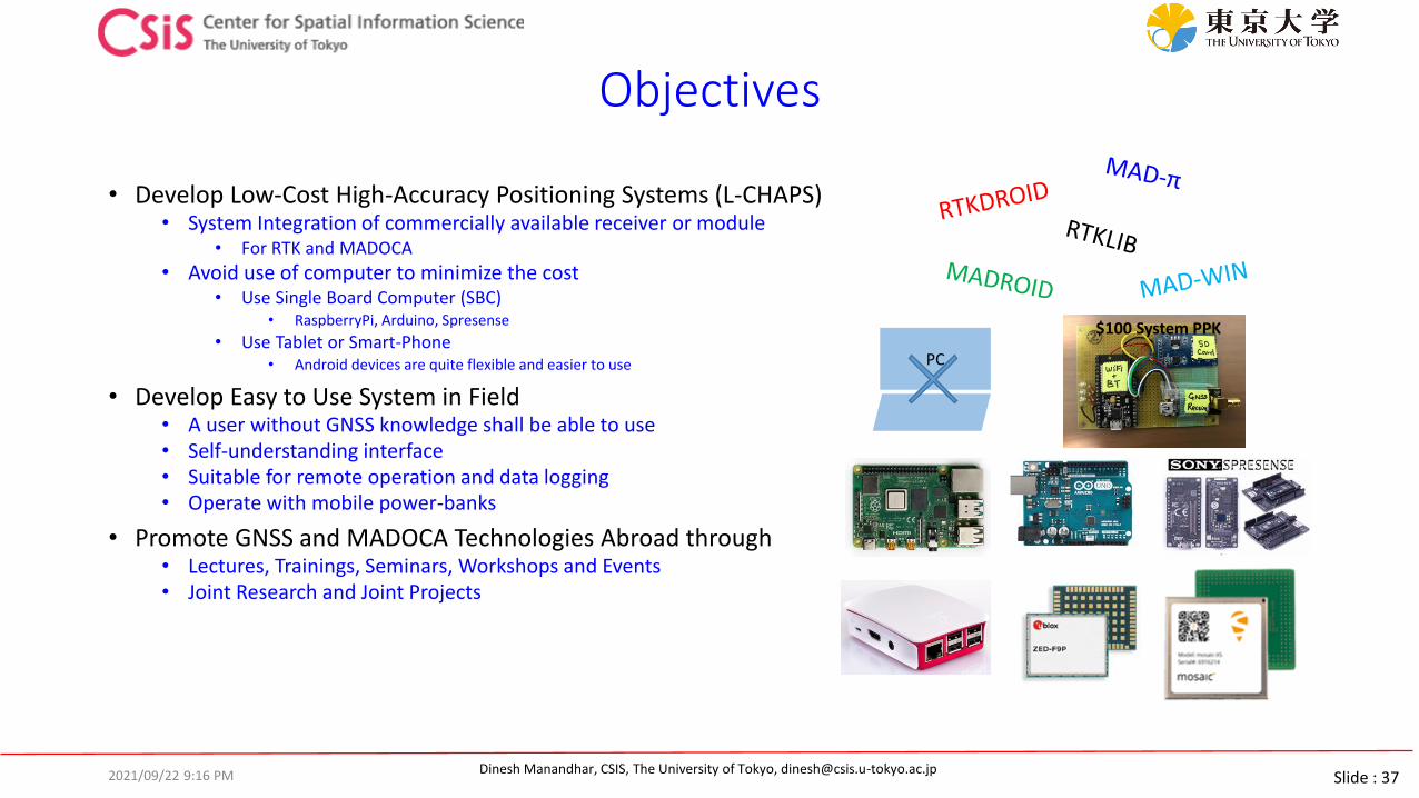
Objectives
• Develop Low-Cost High-Accuracy Positioning Systems (L-CHAPS)• System Integration of commercially available receiver or module
• For RTK and MADOCA
• Avoid use of computer to minimize the cost• Use Single Board Computer (SBC)
• RaspberryPi, Arduino, Spresense
• Use Tablet or Smart-Phone• Android devices are quite flexible and easier to use
• Develop Easy to Use System in Field• A user without GNSS knowledge shall be able to use• Self-understanding interface• Suitable for remote operation and data logging• Operate with mobile power-banks
• Promote GNSS and MADOCA Technologies Abroad through• Lectures, Trainings, Seminars, Workshops and Events• Joint Research and Joint Projects
PC
$100 System PPK
2021/09/22 9:16 PM
Slide : 38Dinesh Manandhar, CSIS, The University of Tokyo, [email protected]
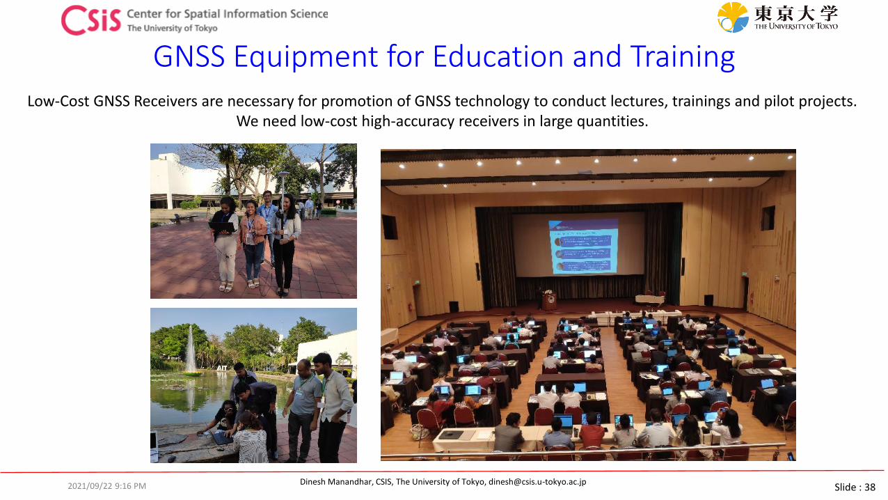
GNSS Equipment for Education and TrainingLow-Cost GNSS Receivers are necessary for promotion of GNSS technology to conduct lectures, trainings and pilot projects.
We need low-cost high-accuracy receivers in large quantities.
2021/09/22 9:16 PM

Slide : 39Dinesh Manandhar, CSIS, The University of Tokyo, [email protected]
Low-Cost High-Accuracy Receiver system Development Cycle
DEC, 2019
Low-Cost MADOCA
DEC, 2016MAY, 2017 MAR, 2018Low-Cost RTK
Enhancement of MADOCA System
2021
Android DeviceRTK / MADOCA / EWS / SAR
System2022
What type of smart-phone will emerge by 2025 ?
2021/09/22 9:16 PM
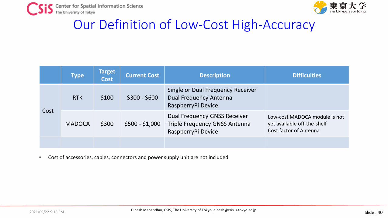
Slide : 40Dinesh Manandhar, CSIS, The University of Tokyo, [email protected]
Our Definition of Low-Cost High-Accuracy
TypeTarget Cost
Current Cost Description Difficulties
Cost
RTK $100 $300 - $600Single or Dual Frequency ReceiverDual Frequency AntennaRaspberryPi Device
MADOCA $300 $500 - $1,000Dual Frequency GNSS ReceiverTriple Frequency GNSS AntennaRaspberryPi Device
Low-cost MADOCA module is not yet available off-the-shelfCost factor of Antenna
• Cost of accessories, cables, connectors and power supply unit are not included
2021/09/22 9:16 PM
Slide : 41Dinesh Manandhar, CSIS, The University of Tokyo, [email protected]
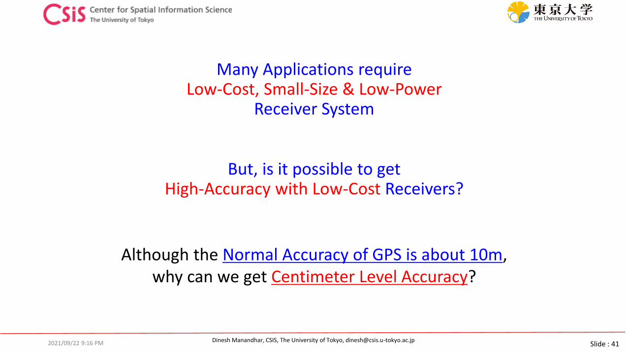
Many Applications require Low-Cost, Small-Size & Low-Power
Receiver System
But, is it possible to get High-Accuracy with Low-Cost Receivers?
Although the Normal Accuracy of GPS is about 10m, why can we get Centimeter Level Accuracy?
2021/09/22 9:16 PM
Slide : 42Dinesh Manandhar, CSIS, The University of Tokyo, [email protected]
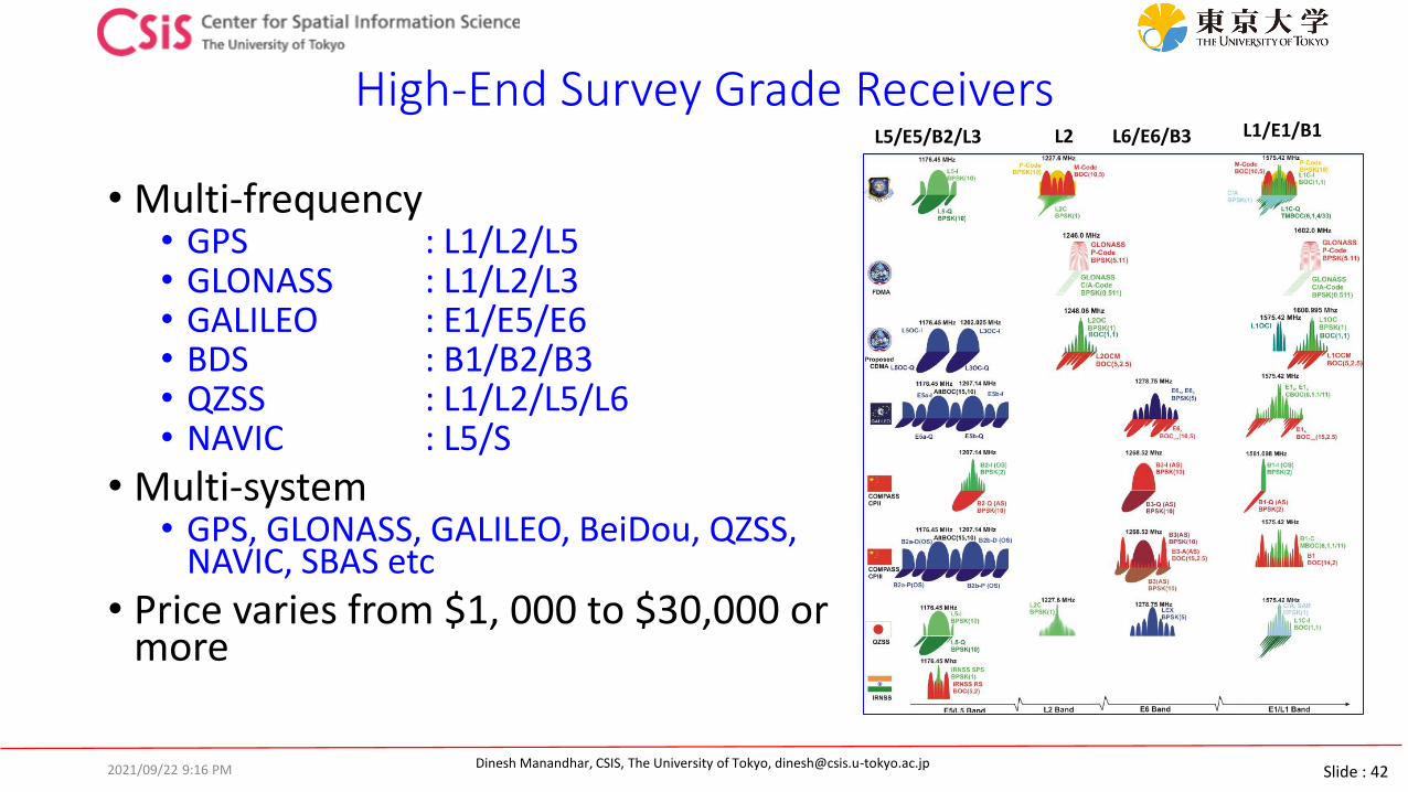
High-End Survey Grade Receivers
• Multi-frequency• GPS : L1/L2/L5• GLONASS : L1/L2/L3• GALILEO : E1/E5/E6• BDS : B1/B2/B3• QZSS : L1/L2/L5/L6• NAVIC : L5/S
• Multi-system • GPS, GLONASS, GALILEO, BeiDou, QZSS,
NAVIC, SBAS etc
• Price varies from $1, 000 to $30,000 or more
L1/E1/B1L6/E6/B3L2L5/E5/B2/L3
2021/09/22 9:16 PM

Slide : 43Dinesh Manandhar, CSIS, The University of Tokyo, [email protected]
Low-Cost Receivers
• Multi-System• GPS, GLONASS, GALILEO, BeiDou, QZSS, SBAS etc
• Basically Single Frequency• L1/E1/B1-Band• Very soon: Multi-System, Multi Frequency, L1/L2 or L1/L5
• Future trend for Mass Market System will be L1/L5• Some chip makers have already announced Multi-System, Multi-
Frequency GNSS Chips for Mass Market
• Low Cost: • Less than $300 (Multi-GNSS, L1 Only) including Antenna and all
necessary Hardware, Software• Our target is within $100 including everything.
L1/E1/B1*
*Note: Only one signal type from each system is processede.g. GPS has L1C/A and L1C in L1, ,but only L1C/A is used in Low-Cost Receiver
2021/09/22 9:16 PM
Slide : 44Dinesh Manandhar, CSIS, The University of Tokyo, [email protected]
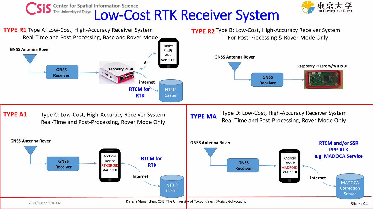
Low-Cost RTK Receiver System
Raspberry Pi 3B
GNSS Antenna Rover
BT
TabletRasPiAPP
Ver. : 1.0
NTRIPCaster
internet
Raspberry Pi Zero w/WiFi&BT
GNSS Antenna Rover
Type A: Low-Cost, High-Accuracy Receiver SystemReal-Time and Post-Processing, Base and Rover Mode
Type C: Low-Cost, High-Accuracy Receiver SystemReal-Time and Post-Processing, Rover Mode Only
Type B: Low-Cost, High-Accuracy Receiver SystemFor Post-Processing & Rover Mode Only
TYPE R1 TYPE R2
TYPE A1 Type D: Low-Cost, High-Accuracy Receiver SystemReal-Time and Post-Processing, Rover Mode Only
TYPE MA
RTCM for RTK
GNSS Antenna Rover
AndroidDevice
RTKDROIDVer. : 1.0
NTRIPCaster
Internet
RTCM for RTK GNSS
Receiver
GNSS Antenna Rover
MADOCACorrection
Server
Internet
RTCM and/or SSRPPP-RTK
e.g. MADOCA Service
GNSS Receiver
GNSS Receiver
GNSS Receiver
AndroidDevice
MADROIDVer. : 1.0
2021/09/22 9:16 PM

Slide : 45Dinesh Manandhar, CSIS, The University of Tokyo, [email protected]
Type – A1: GNSS Receiver with Android Device
GNSS Receiver
GNSS Antenna Rover
AndroidDevice
RTKDROIDVer. : 1.0
NTRIPCaster
WiFi
RTCM for Real-time
RTK
Type A1: Rover Mode
Real-Time and Post-Processing RTKBased on RTKLIB Engine
Real-time processing in Android DeviceAPP: RTKDroid
GNSS Receiver Module
2021/09/22 9:16 PM
Slide : 46Dinesh Manandhar, CSIS, The University of Tokyo, [email protected]
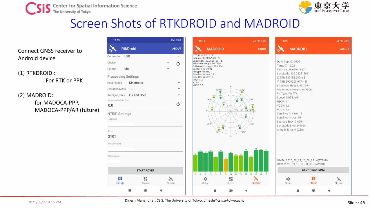
Screen Shots of RTKDROID and MADROID
Connect GNSS receiver to Android device
(1) RTKDROID : For RTK or PPK
(2) MADROID: for MADOCA-PPP, MADOCA-PPP/AR (future)
2021/09/22 9:16 PM
Slide : 47Dinesh Manandhar, CSIS, The University of Tokyo, [email protected]
MADOCA System: Direct from QZSS or Online Correction Data
GNSS / MADOCA Receiver
Antenna
QZSS
MADOCA PPP Processor
Position Output
GNSS Receiver + MADOCA Decoder
GN
SS S
ign
als
GNSS Receiver
Antenna
QZSS
MADOCA PPP Processor
Position Output
Online MADOCA Correction Data
GNSS Receiver Only
GN
SS S
ign
als
2021/09/22 9:16 PM

Slide : 48Dinesh Manandhar, CSIS, The University of Tokyo, [email protected]
How does MADOCA Work?
• MADOCA• Multi-GNSS Advanced Demonstration tool for Orbit and Clock Analysis
• Provides an accuracy of 10cm
• MADOCA signal broadcasts the following correction data: • Satellite Orbit, Satellite Clock, Signal Biases
• Currently, correction data are broadcasted for GPS, GLOANSS and QZSS satellites
2021/09/22 9:16 PM
Image from presentation file: Introduction to MADOCA by H. Kakimoto, GPAS Company
product
Interval RTCM Message
Estimate Provide GPS GLONASS QZSS
Orbit correction 30 1 1057 1063 1246
Clock correction 1 1 1058 1064 1247
HR-Clock correction 1 1 1062 1068 1251
URA 1 1 1061 1067 1250
Table Source: https://www.gpas.co.jp/service_madoca.php
Slide : 49Dinesh Manandhar, CSIS, The University of Tokyo, [email protected]
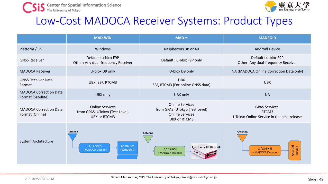
Low-Cost MADOCA Receiver Systems: Product TypesMAD-WIN MAD-π MADROID
Platform / OS Windows RaspberryPi 3B or 4B Android Device
GNSS ReceiverDefault : u-blox F9P
Other: Any dual-frequency ReceiverDefault : u-blox F9P only
Default : u-blox F9POther: Any dual-frequency Receiver
MADOCA Receiver U-blox D9 only U-blox D9 only NA (MADOCA Online Correction Data only)
GNSS Receiver Data Format
UBX, SBF, RTCM3UBX
SBF, RTCM3 (For online GNSS data)UBX
MADOCA Correction Data Format (Satellite)
UBX only UBX only NA
MADOCA Correction Data Format (Online)
Online Services from GPAS, UTokyo (Test Level)
UBX or RTCM3
Online Services from GPAS, UTokyo (Test Level)
Online ServicesUBX or RTCM3
GPAS Services, RTCM3
UTokyo Online Service in the next release
System Architecture
2021/09/22 9:16 PM

Slide : 50Dinesh Manandhar, CSIS, The University of Tokyo, [email protected]
MADOCA PPP Receiver System
50
65
GNSS Antenna
Antenna
F9P GNSS ReceiverL1/L2/E5B
MADOCA DecoderQZSS L6
COM Port: 1GNSS Data
COM Port: 2MADOCA Data
Use this baud-rate to receiverGNSS Raw Data
Use this baud-rate to receiverMADOCA Data
2021/09/22 9:16 PM

Slide : 51Dinesh Manandhar, CSIS, The University of Tokyo, [email protected]
MAD-WIN / MAD-PI User Interface
Log Files: 1. Solution: MADOCA PPP Solution in NEMA format2. Rover: Rover RAW Data in receiver’s proprietary formatCan be used for PPK (Post-Processing Kinematic) Solution or Post-Processing PPP3. Correction: MADOCA PPP Correction Data in receiver’s proprietary formatCan be used for Post-Processing MADOCA
2021/09/22 9:16 PM

Slide : 52Dinesh Manandhar, CSIS, The University of Tokyo, [email protected]
MAD-WIN Data ObservationReceiver: Online receiver access in Kashiwa / Correction Data: MADOCA Receiver in Bali
After few minutes observation
After two hours observation
After three hours observation
2021/09/22 9:16 PM

Slide : 53Dinesh Manandhar, CSIS, The University of Tokyo, [email protected]
MAD-PI:MADOCA with RaspberryPi Device
• MAD-Pi has been tested with RaspberryPi-3B device• It also works with RaspberryPi-4B
• If the device does not work, please try with a different USB port
• Do not remove and insert SD Card several times. It may get damaged.
• Observation data can be logged to an external USB memory disk. Memory drive of upto 64GB is supported.
• Files are created at 6-hour interval with Date/Time based filename.
• Ras-Pi 4 device consumes more power than Ras-Pi 3 device. Continuous operation of the device will generate heat. Keep the device in well ventilated area
• Do not keep the device in a closed box
• We have set both Ras-Pi 3 and Ras-Pi 4 devices with touch screens for easy operation.
• Mouse and External keyboard can be connected either via BT or USB ports
• Ras-Pi device can be connected by an Android device using BT
Raspberry-Pi device with Touch Screen
2021/09/22 9:16 PM
Slide : 54Dinesh Manandhar, CSIS, The University of Tokyo, [email protected]
MADOCA Data Processing
2021/09/22 9:16 PM

Slide : 55Dinesh Manandhar, CSIS, The University of Tokyo, [email protected]
GNSS Data Processing Software• Software
• U-center v.21.05• Data logging and viewing software from u-blox. Necessary to log and set-up
u-blox receivers
• https://www.u-blox.com/en/product/u-center
• Also, u-center 2 v.21.08 is available. You may try it, but we use u-center for exercise.
• RTKLIB• RTKLIB is very powerful software for RTK and PPP. It has many functions for
data conversion, data logging for RTK, DGPs etc.
• RTKLIB V. 2.4.3 b34
• http://www.rtklib.com/
• https://github.com/tomojitakasu/RTKLIB_bin/tree/rtklib_2.4.3
• RTKDROID• https://home.csis.u-tokyo.ac.jp/~dinesh/LCHAR.htm
• RTK Software based on RTKLIB for android device.
• Only for use with u-blox M8T, M8P or F9P receivers connected to an android device
• MAD-WIN / MAD-PI / MADROID• MAD-WIN is for MADOCA-PPP processing for high-accuracy for Windows PC.
• Google drive link will be provided to download software
Download this one
1. Select Code
2. Download ZIP

Slide : 56Dinesh Manandhar, CSIS, The University of Tokyo, [email protected]
Request for HW/SW• MADOCA Receiver Systems are distributed to overseas universities for joint
research and pilot projects
• Includes HW and SW
• Signing of MTA (Material Transfer Agreement) Document is necessary for HW
• If only SW is required, please send request through
• https://home.csis.u-tokyo.ac.jp/~dinesh/LCHAR.htm
• SW is provided under the understanding that the recipients provide feedbacks and some sample data
• Feedbacks are necessary to improve and debug the products
2021/09/22 9:16 PM
Slide : 57Dinesh Manandhar, CSIS, The University of Tokyo, [email protected]
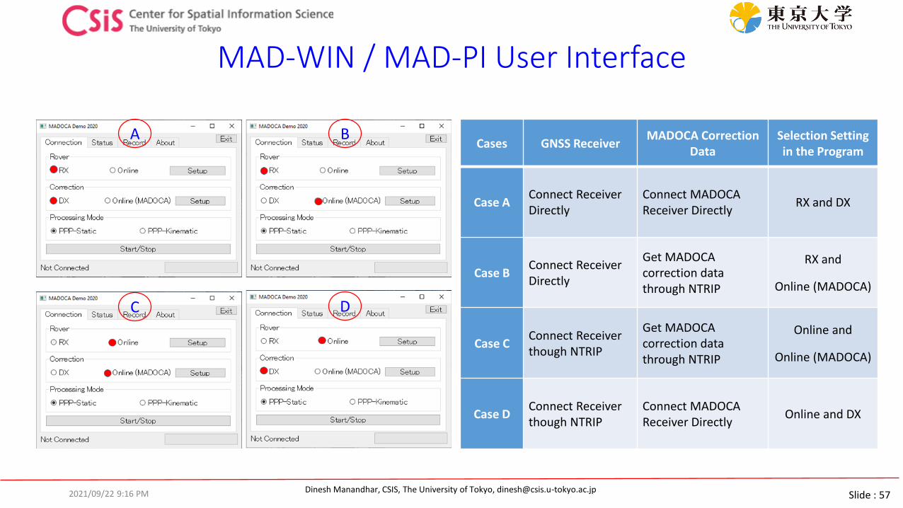
MAD-WIN / MAD-PI User Interface
Cases GNSS ReceiverMADOCA Correction
DataSelection Setting in the Program
Case AConnect Receiver Directly
Connect MADOCA Receiver Directly
RX and DX
Case BConnect Receiver Directly
Get MADOCA correction data through NTRIP
RX and
Online (MADOCA)
Case CConnect Receiver though NTRIP
Get MADOCA correction data through NTRIP
Online and
Online (MADOCA)
Case DConnect Receiver though NTRIP
Connect MADOCA Receiver Directly
Online and DX
A B
C D
2021/09/22 9:16 PM
Slide : 58Dinesh Manandhar, CSIS, The University of Tokyo, [email protected]
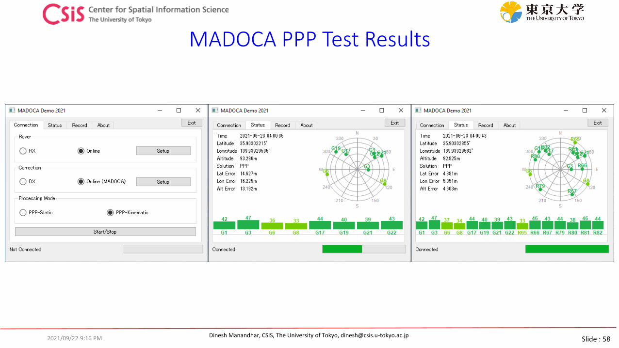
MADOCA PPP Test Results
2021/09/22 9:16 PM
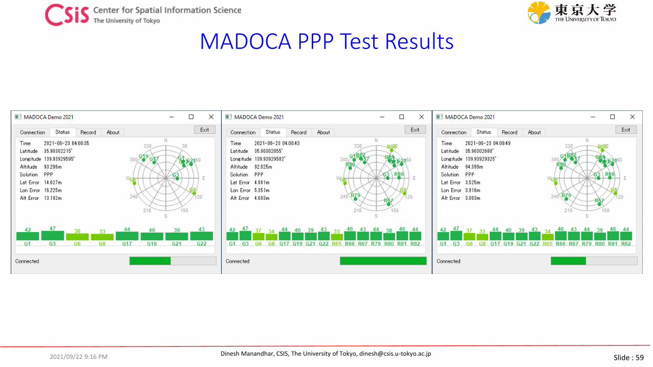
Slide : 59Dinesh Manandhar, CSIS, The University of Tokyo, [email protected]
MADOCA PPP Test Results
2021/09/22 9:16 PM

Slide : 60Dinesh Manandhar, CSIS, The University of Tokyo, [email protected]
MADOCA PPP Test Results
2021/09/22 9:16 PM
Slide : 61Dinesh Manandhar, CSIS, The University of Tokyo, [email protected]
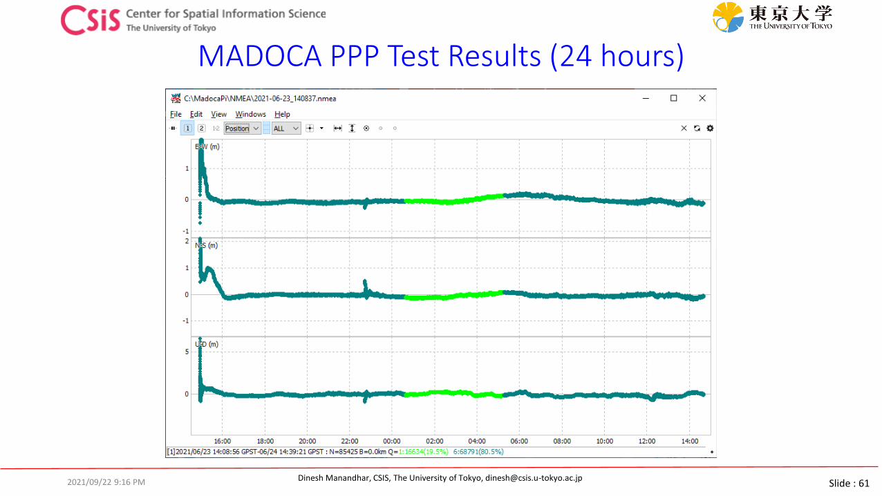
MADOCA PPP Test Results (24 hours)
2021/09/22 9:16 PM

Slide : 62Dinesh Manandhar, CSIS, The University of Tokyo, [email protected]
MADOCA PPP Test Results (24 hours)
2021/09/22 9:16 PM

Slide : 63Dinesh Manandhar, CSIS, The University of Tokyo, [email protected]
MADROID: MADOCA with Android Device
2021/09/22 9:16 PM
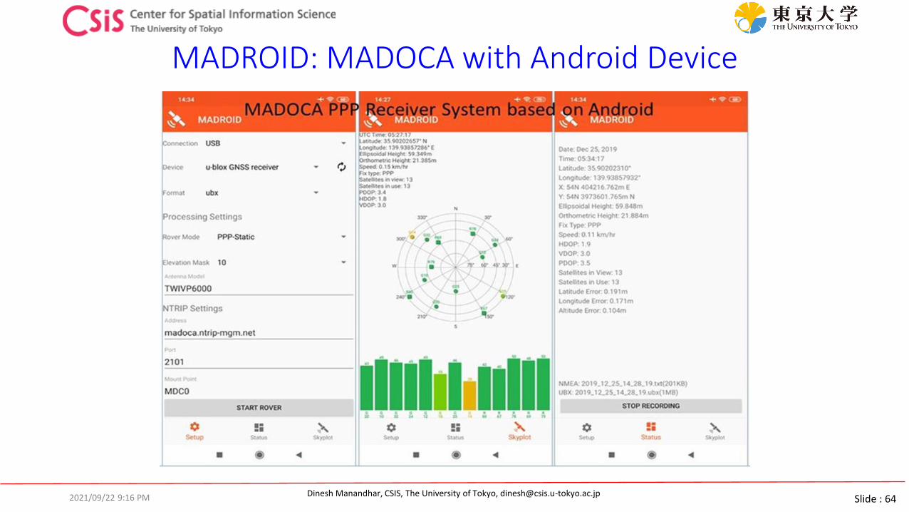
Slide : 64Dinesh Manandhar, CSIS, The University of Tokyo, [email protected]
MADROID: MADOCA with Android Device
2021/09/22 9:16 PM
Slide : 65Dinesh Manandhar, CSIS, The University of Tokyo, [email protected]
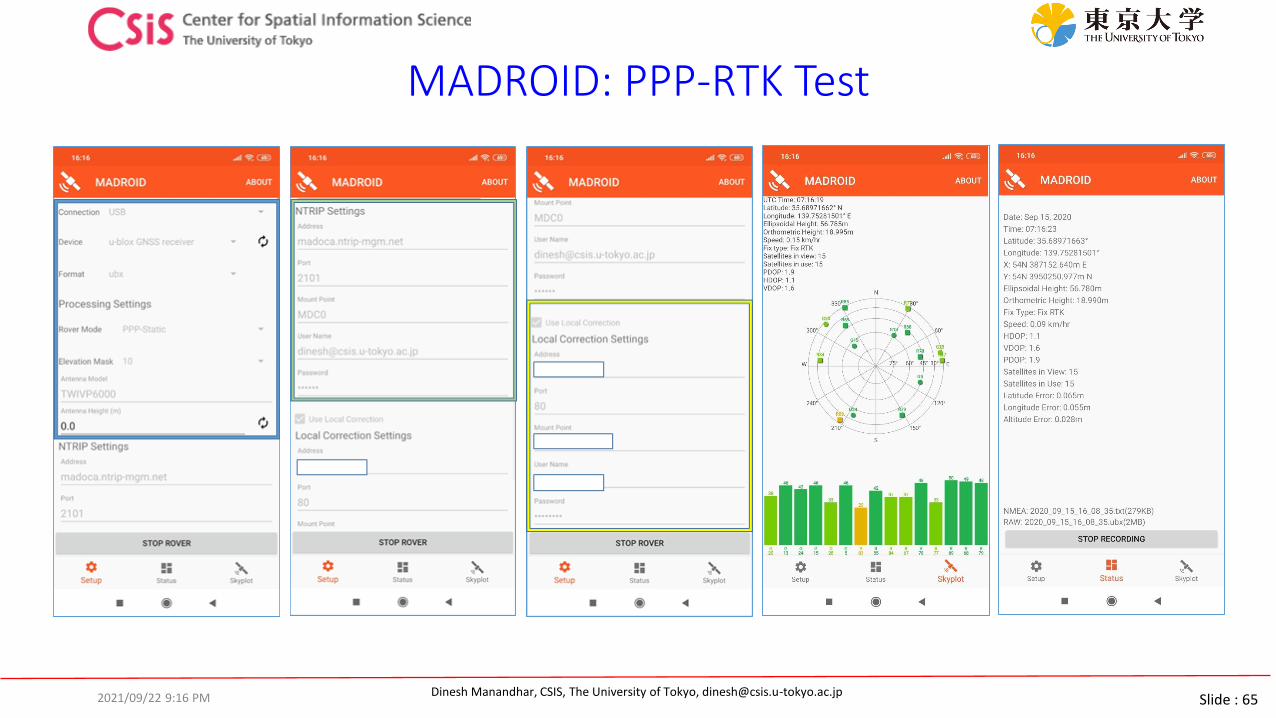
MADROID: PPP-RTK Test
2021/09/22 9:16 PM

Slide : 66Dinesh Manandhar, CSIS, The University of Tokyo, [email protected]
Low-Cost MADOCA Receiver for Sea-Level Rise Measurement
Source: Technical Report, GNSS/QZSS MADOCA PPP Data Acquisition for Sea Level Rise Measurement, DR. ROSALIE B. REYES, UP DGE and Project Leader, CLSR-Phil Project
2021/09/22 9:16 PM

Slide : 67Dinesh Manandhar, CSIS, The University of Tokyo, [email protected]
GNSS Technology Promotion Activities
2021/09/22 9:16 PM
Slide : 68Dinesh Manandhar, CSIS, The University of Tokyo, [email protected]
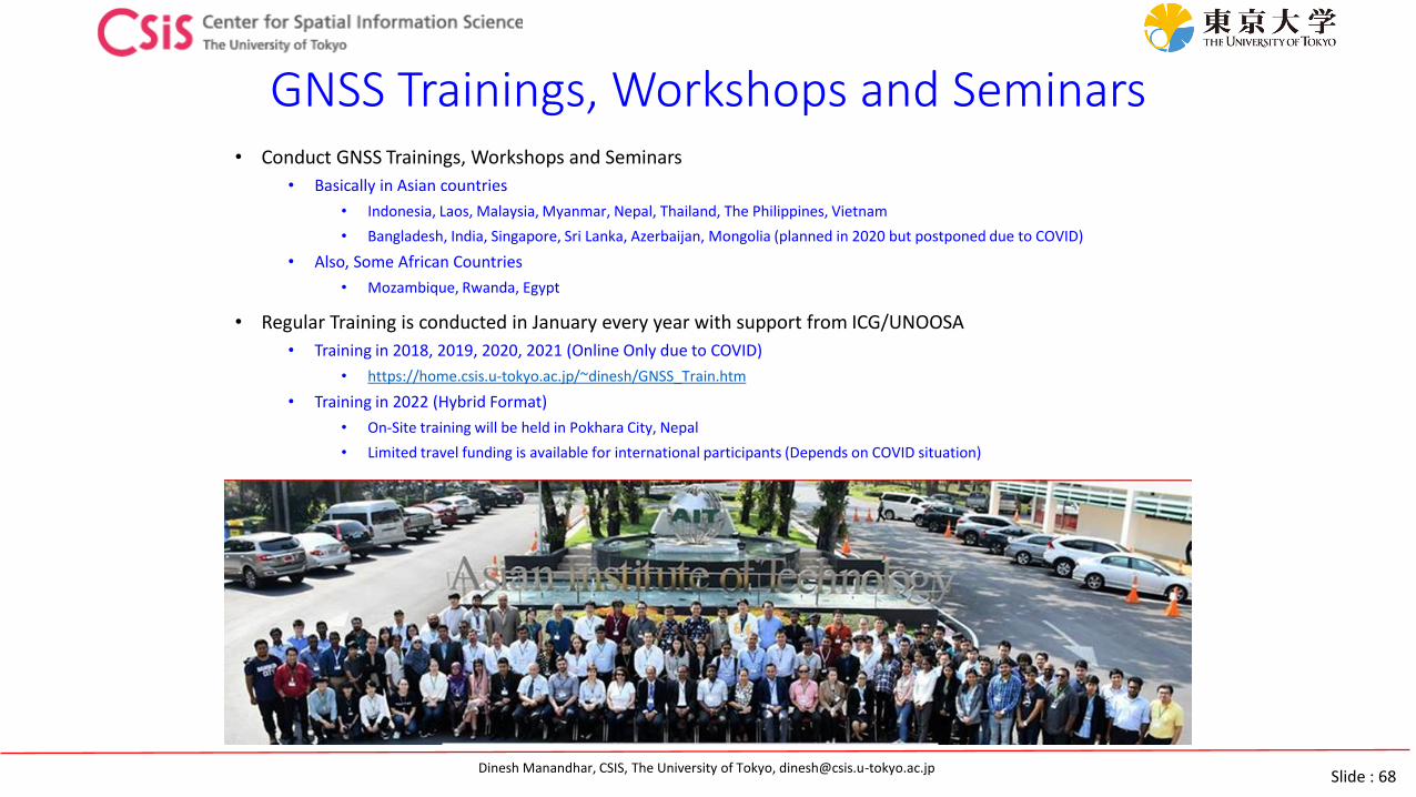
GNSS Trainings, Workshops and Seminars• Conduct GNSS Trainings, Workshops and Seminars
• Basically in Asian countries
• Indonesia, Laos, Malaysia, Myanmar, Nepal, Thailand, The Philippines, Vietnam
• Bangladesh, India, Singapore, Sri Lanka, Azerbaijan, Mongolia (planned in 2020 but postponed due to COVID)
• Also, Some African Countries
• Mozambique, Rwanda, Egypt
• Regular Training is conducted in January every year with support from ICG/UNOOSA
• Training in 2018, 2019, 2020, 2021 (Online Only due to COVID)
• https://home.csis.u-tokyo.ac.jp/~dinesh/GNSS_Train.htm
• Training in 2022 (Hybrid Format)
• On-Site training will be held in Pokhara City, Nepal
• Limited travel funding is available for international participants (Depends on COVID situation)
Slide : 69Dinesh Manandhar, CSIS, The University of Tokyo, [email protected]
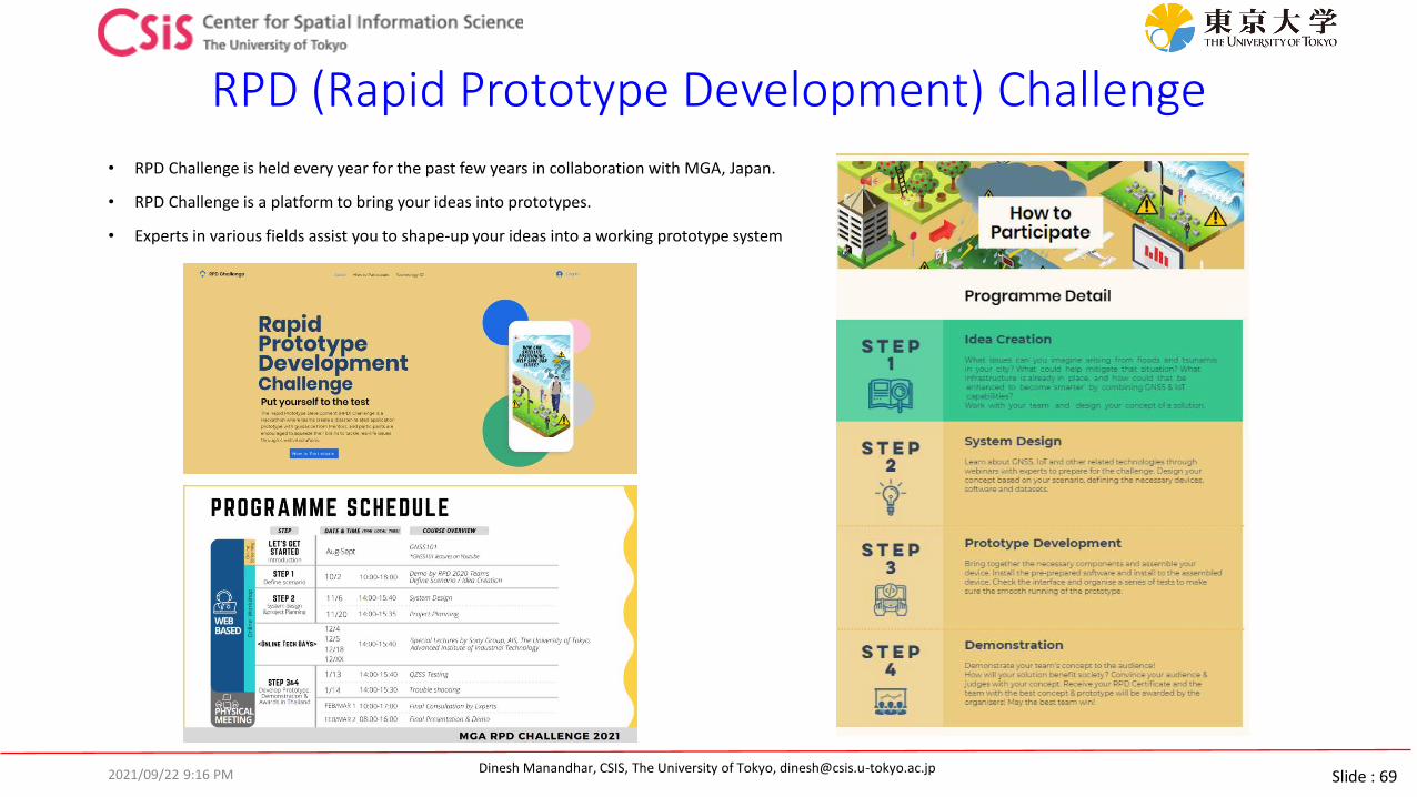
RPD (Rapid Prototype Development) Challenge
• RPD Challenge is held every year for the past few years in collaboration with MGA, Japan.
• RPD Challenge is a platform to bring your ideas into prototypes.
• Experts in various fields assist you to shape-up your ideas into a working prototype system
2021/09/22 9:16 PM

Slide : 70Dinesh Manandhar, CSIS, The University of Tokyo, [email protected]
Summary and Future Plans
• QZSS provides unique services for Early Warning System and High-Accuracy Positioning.
• We have developed Low-Cost MADOCA receiver systems • MAD-WIN, MAD-PI and MADROID
• MAD-PI will be improved for remote data logging.
• We will integration of current system with other systems• Traffic monitoring, EWS Application, GIS data collection tool, ……..
• Trainings, Seminars, Workshops and Joint Projects with foreign universities will be conducted• Please join our programs for further promotion of the technology in the region
• We share GNSS data from different types of receivers• Data from high-end survey grade receivers to low-cost receivers are available upon request
Refer https://home.csis.u-tokyo.ac.jp/~dinesh/ for more information.
2021/09/22 9:16 PM