introduction to ospf v2
DESCRIPTION
Introduction to OSPF v2TRANSCRIPT
Campus Networking Workshop
Introduction to OSPF
Agenda
• Basic Elements of OSPF• OSPF in Service Provider Networks• Best Common Practices in OSPF –
Network Aggregation• OSPF Command Reference

Basic Elements of OSPF

OSPF
• Open ShortestPath First
• Link State or SPF technology
• Developed by the IETF’s OSPF working group (RFC 1247)
• Designed for TCP/IP • Fast Convergence
• Variable length netmasks• Non-contiguous subnets• No need for periodic updates• Route authentication• OSPF is defined in RFC2328

Link-State
Topology information is stored in a DB separate from the routing table
AABBCC
2213131313
QQZZXX
X’s Link-state
ZZ
XX
YYQQ
Z’s Link-stateQ’s Link-state
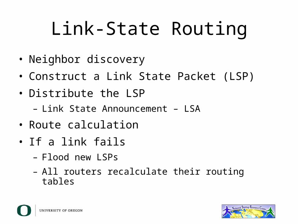
Link-State Routing• Neighbor discovery• Construct a Link State Packet (LSP)• Distribute the LSP
– Link State Announcement – LSA
• Route calculation• If a link fails
– Flood new LSPs– All routers recalculate their routing tables

FDDIDual Ring
Low Bandwidth Utilization
• Only propagate changes• Use Multicast in multi-access networks
R1
LSA
XLSA
FDDI Dual Ring
FDDI Dual Ring
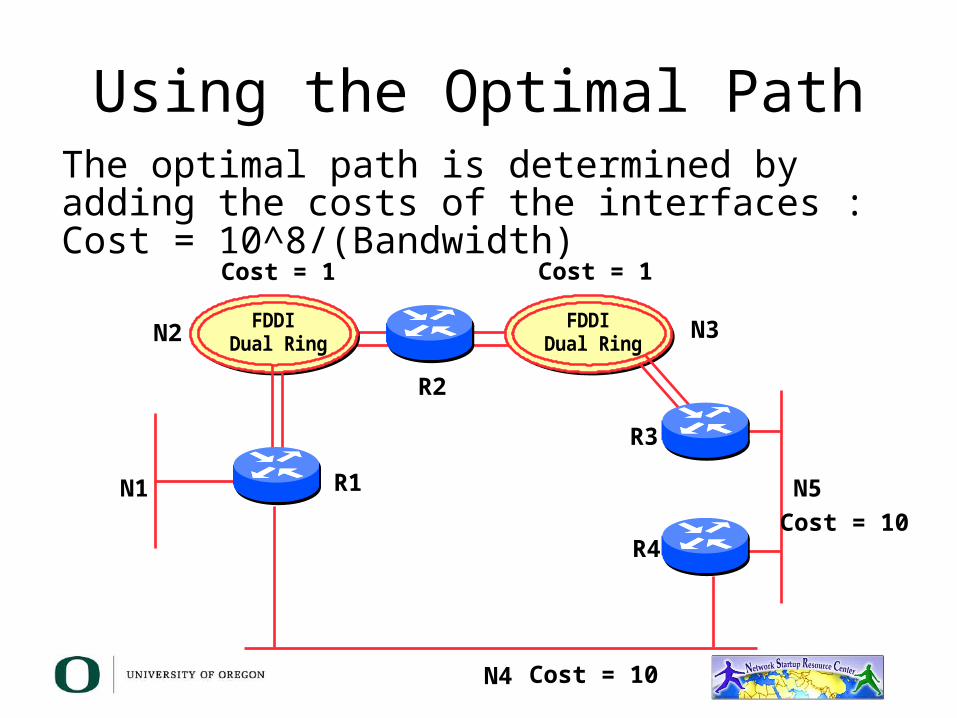
Using the Optimal PathThe optimal path is determined by adding the costs of the interfaces : Cost = 10^8/(Bandwidth)
N1
N2 N3
N4
N5R1
R2
R3
R4
Cost = 1 Cost = 1
Cost = 10
Cost = 10
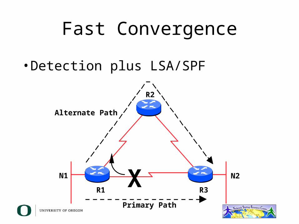
Fast Convergence
• Detection plus LSA/SPF
XR1 R3
R2
N2
Alternate Path
Primary Path
N1
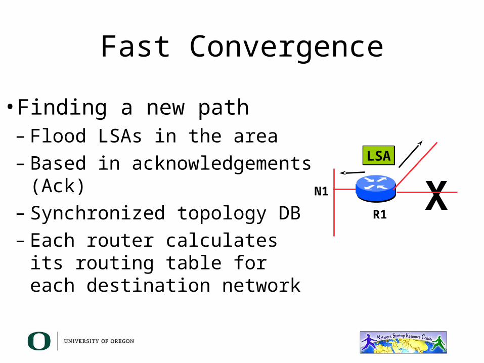
Fast Convergence
• Finding a new path– Flood LSAs in the area– Based in acknowledgements
(Ack)– Synchronized topology DB– Each router calculates its routing
table for each destination network
LSA
XR1
N1

Uses IP Multicast to Send/Receive changes
• Multi-Access networks– All routers must accept packets sent to the AllSPFRouters
(224.0.0.5) address– All DR and BDR routers must accept packets sent to the
AllDRouters (224.0.0.6) address
• Hello packets are sent to the AllSPFRouters address (Unicast for point-to-point and virtual links)
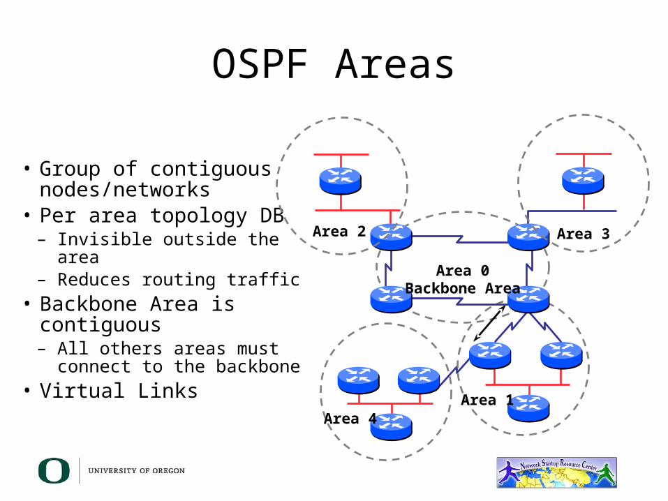
OSPF Areas
• Group of contiguous nodes/networks
• Per area topology DB– Invisible outside the area– Reduces routing traffic
• Backbone Area is contiguous– All others areas must connect to
the backbone• Virtual Links
Area 1Area 4
Area 0Backbone Area
Area 2 Area 3

Router Classification
• Internal Router (IR)• Area Border Router
(ABR)• Backbone Router (BR)• Autonomous System
Border Router (ASBR)Area 1
IR/BR
Area 0
Area 2 Area 3
IR
ABR/BR
To another AS
ASBR
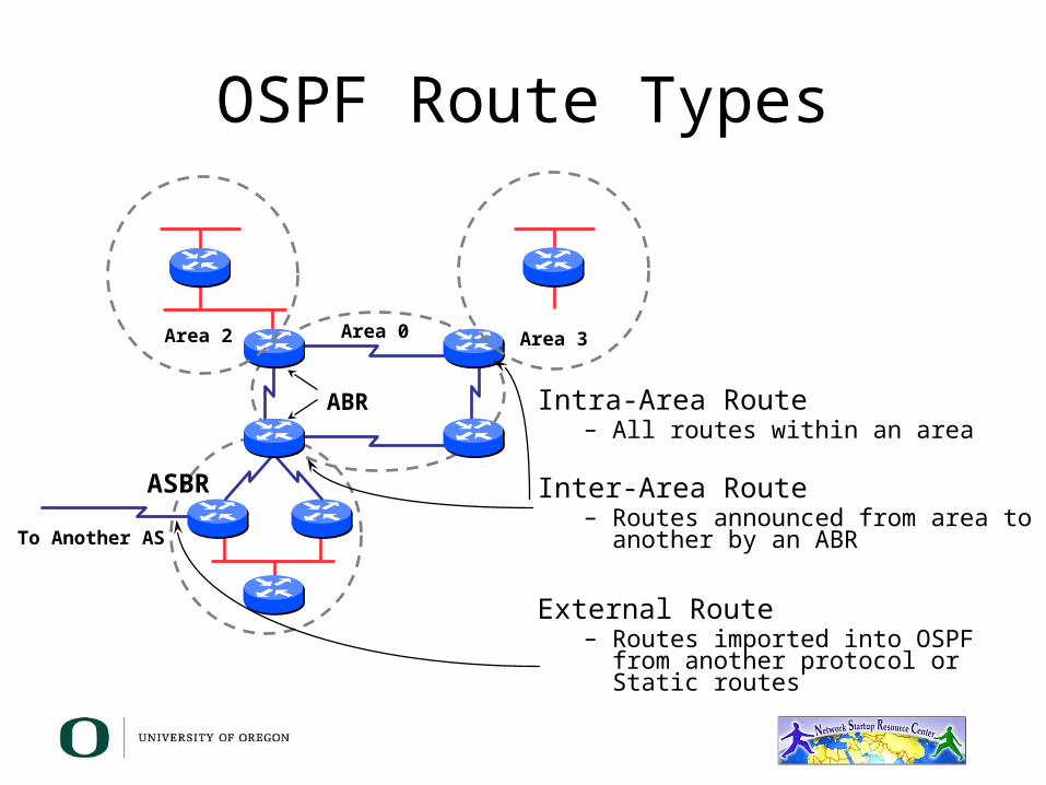
OSPF Route Types
Intra-Area Route– All routes within an area
Inter-Area Route– Routes announced from area to
another by an ABR
External Route– Routes imported into OSPF from
another protocol or Static routes
Area 0Area 2 Area 3
ABR
To Another AS
ASBR

Inter-Area Route Summarization
• Prefix or all subnets• Prefix or all networks• ‘Area range’ command
1.A 1.B 1.C
FDDIDual Ring
R1 (ABR)
R2
Network1
Next HopR1
Network1.A1.B1.C
Next HopR1R1R1
With Summarization
WithoutSummarization
BackboneArea 0
Area 1
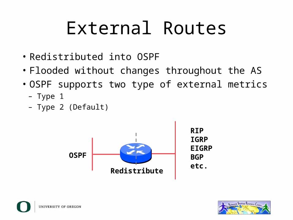
External Routes• Redistributed into OSPF• Flooded without changes throughout the AS• OSPF supports two type of external metrics
– Type 1– Type 2 (Default)
RIPIGRPEIGRPBGPetc.
OSPF
Redistribute
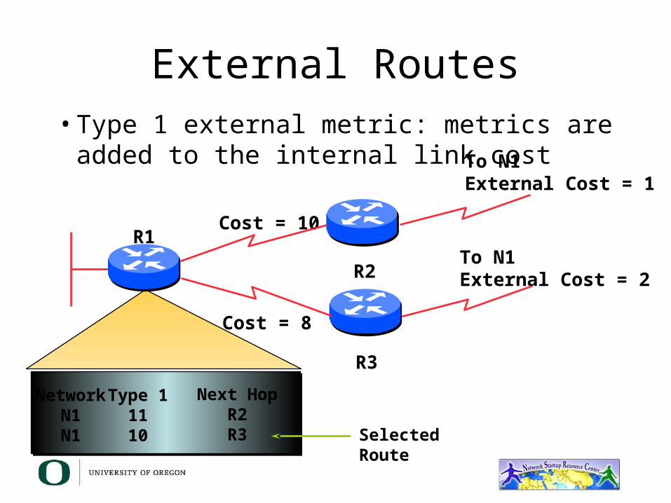
External Routes• Type 1 external metric: metrics are added to
the internal link cost
NetworkN1N1
Type 11110
Next HopR2R3
Cost = 10
To N1External Cost = 1
To N1External Cost = 2R2
R3
R1
Cost = 8
Selected Route
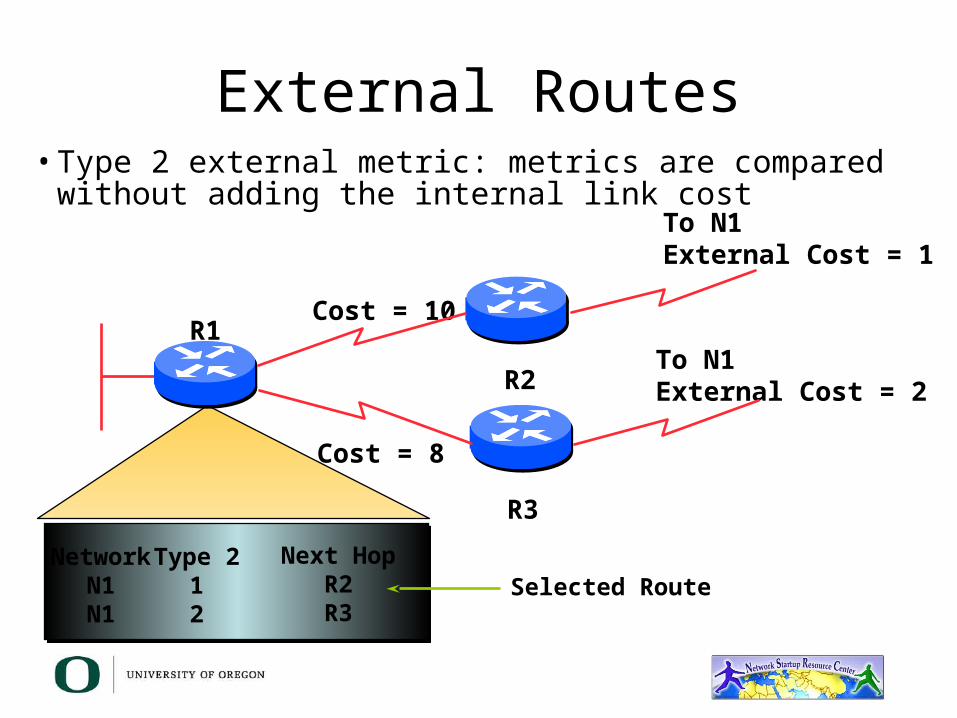
External Routes• Type 2 external metric: metrics are compared
without adding the internal link cost
NetworkN1N1
Type 212
Next HopR2R3
Cost = 10
To N1External Cost = 1
To N1External Cost = 2R2
R3
R1
Cost = 8
Selected Route

Topology/Links-State DB
• A router has a separate DB for each area it belongs
• All routers within an area have an identical DB• SPF calculation is done separately for each area• LSA flooding is limited to the particular area
Protocol Functionality
• Bringing up adjacencies• LSA Types• Area Classification

The Hello Protocol• Responsible to establish and maintain neighbor
relationships• Elects designated router in multi-access
networks
FDDIDual Ring
Hello
HelloHello
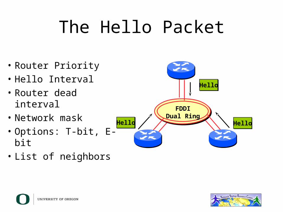
The Hello Packet
• Router Priority• Hello Interval• Router dead interval• Network mask• Options: T-bit, E-bit• List of neighbors
FDDIDual Ring
Hello
HelloHello
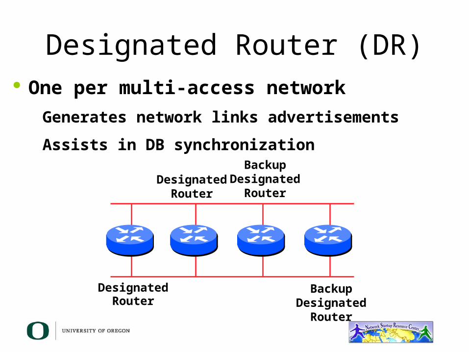
Designated Router (DR) One per multi-access network
Generates network links advertisements
Assists in DB synchronization
DesignatedRouter
DesignatedRouter
BackupDesignated
Router
BackupDesignated
Router

Designated Router by Priority• Configured priority (per interface)• Otherwise determined by the highest router ID
– The router ID is the loopback interface address, in configured otherwise is the highest IP address
144.254.3.5
R2 Router ID = 131.108.3.3
131.108.3.2 131.108.3.3
R1 Router ID = 144.254.3.5
DR
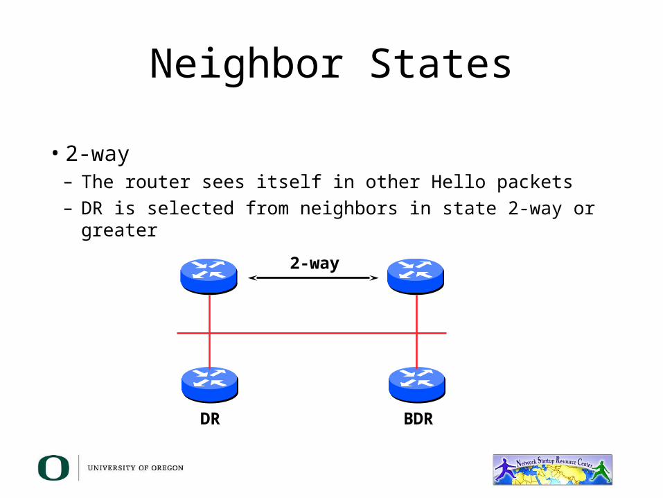
Neighbor States
• 2-way– The router sees itself in other Hello packets– DR is selected from neighbors in state 2-way or greater
DR BDR
2-way

Neighbor States
• Full– Routers are fully adjacent– DB is synchronized– Relationship to the DR and
BDR
DR BDR
Full

When to Become Adjacent
• Underlying network is point-to-point• Underlying network type is virtual link• The router itself is the DR• The router itself is the BDR• The neighboring router is the DR• The neighboring router is the BDR

LSAs Propagate Along Adjacencies
• LSAs acknowledged along adjacencies
DR BDR

Routing Protocol Packets
• Share a common protocol header• Routing protocol packets are sent with a TOS of 0• Five types of OSPF routing protocol packets
– Hello – packet type 1– DB Description – packet type 2– Link-state request – packet type 3– Link-state update – packet type 4– Link-state Acknowledgment – packet type 5
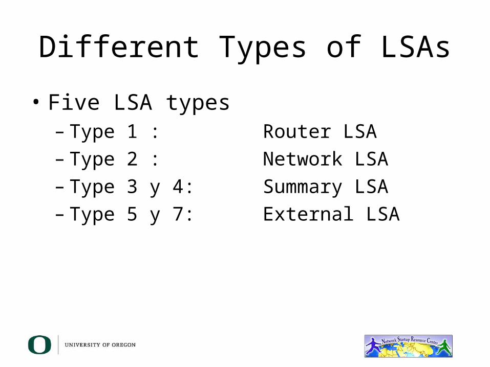
Different Types of LSAs
• Five LSA types– Type 1 : Router LSA– Type 2 : Network LSA– Type 3 y 4: Summary LSA– Type 5 y 7: External LSA
Router LSA (Type 1)
• Describes the state and cost of the router’s link to the area
• All the router’s links in an area must be described in a single LSA
• Flooded throughout the particular area and not beyond
• Router indicates whether it is an ASBR, ABR, or the end point of a virtual link
Network LSA (Type 2)
• Generated for every transit broadcast or NBMA network
• Describes all the routers attached to the network
• Only the DR originates this type of LSA• Flooded throughout the area and not beyond
Summary LSA (Type 3 y 4)
• Describes a destination outside the area but still within the AS
• Flooded throughout a single area• Originated by an ABR• Only intra-area routes are advertised into
the backbone (Area 0)• Type 4 is the information about the ASBR
External LSA (Type 5)
• Defines routes to destinations outside the AS• Default route is also sent as external• Two Types of external LSA:
• E1: Considers the total cost of to the external destination• E2: Considers only the cost of the outgoing interface to the
external destination

Not Summarized: Specific Link
• Specific link LSA advertised out• Link state changes propagate out
BackboneArea #0
External Links
1.A
1.C
1.B
1.D
TokenRing
TokenRing
TokenRing
TokenRing
3.D
3.A
3.C
3.B
1.A1.B1.C1.D
3.A3.B3.C3.D
2.A2.B2.C
2.A
2.C
2.B
TokenRing
TokenRing
ASBR
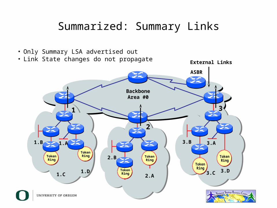
Summarized: Summary Links
• Only Summary LSA advertised out• Link State changes do not propagate
BackboneArea #0
ASBR
External Links
1.A
1.C
1.B
1.D
TokenRing
TokenRing
TokenRing
TokenRing
3.D
3.A
3.C
3.B
2.A
2.B
TokenRing
TokenRing
1 3
2

BackboenArea #0
External Links
1.A
1.C
1.B
1.D
TokenRing
TokenRing
TokenRing
TokenRing
3.D
3.A
3.C
3.B
2.A
2.C
2.B
TokenRing
TokenRing
ASBR
Not Summarized: Specific Links
• Specific Link LSA advertised in• Links state changes propagate in
2.A2.B2.C3.A3.B3.C3.D
1.A1.B1.C1.D3.A3.B3.C3.D
1.A1.B1.C1.D2.A2.B2.C
ASBR
External Links
1.A
1.C
1.B
1.DTokenRing
TokenRing
TokenRing
TokenRing
3.C
3.B
2.ATokenRing
TokenRing
2,3
1,3
1,2
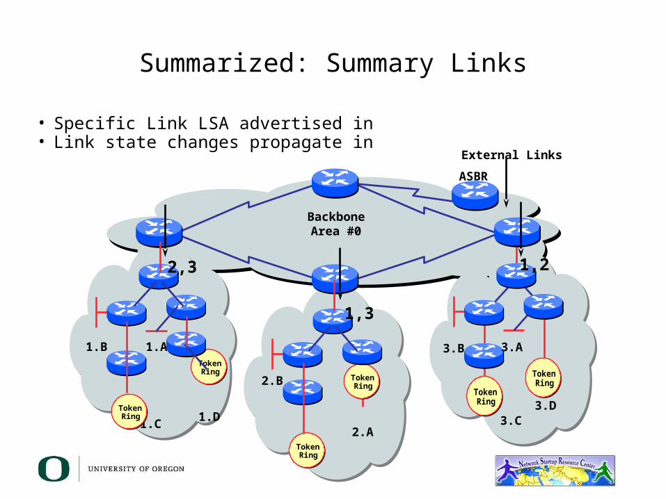
Summarized: Summary Links
• Specific Link LSA advertised in• Link state changes propagate in
BackboneArea #0
3.D
3.A
2.B
TokenRing
TokenRing
TokenRing
TokenRing
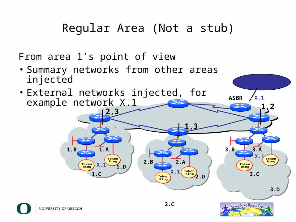
Regular Area (Not a stub)
From area 1’s point of view• Summary networks from other areas injected• External networks injected, for example
network X.1 ASBRExternal Networks
1.A
1.C
1.B
1.D TokenRing
TokenRing
3.C
3.B
2.A
2,3
1,3
1,2X.1
X.1
X.1X.1
2.D
2.C
2.B
3.A
3.D
TokenRing
TokenRing
TokenRing
TokenRing
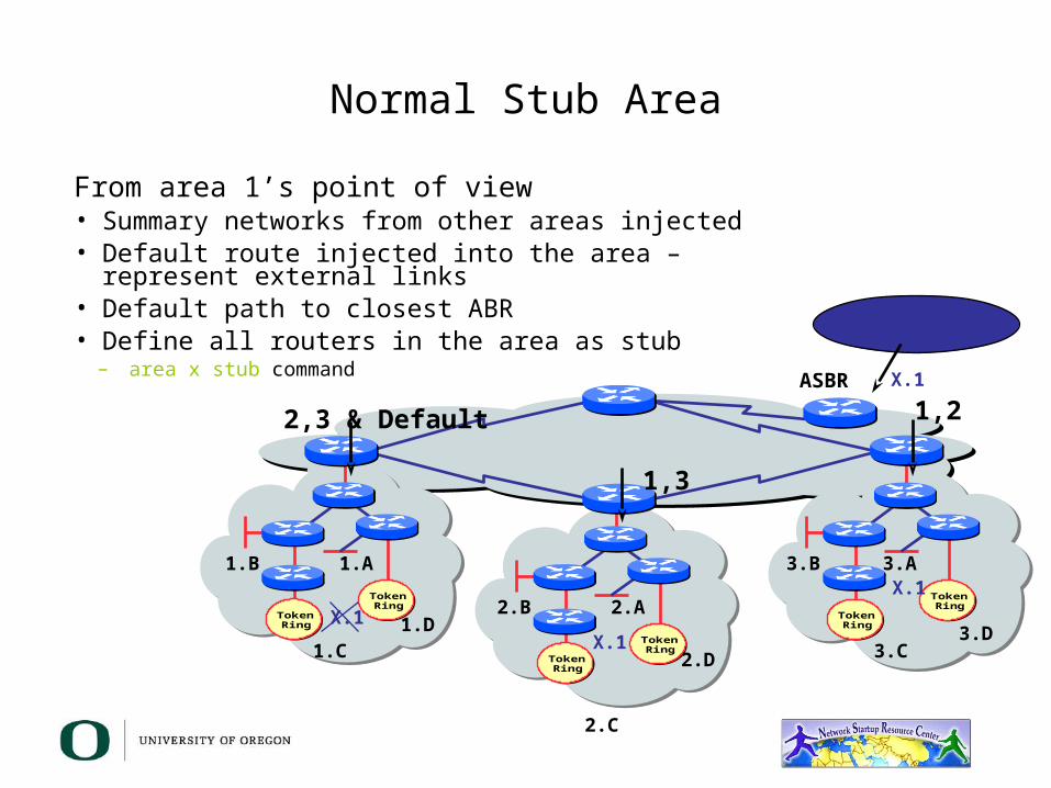
Normal Stub Area
From area 1’s point of view• Summary networks from other areas injected• Default route injected into the area – represent external
links• Default path to closest ABR• Define all routers in the area as stub
– area x stub command ASBRExternal Networks
1.A
1.C
1.B
1.D TokenRing
TokenRing
3.C
3.B
2.A
2,3 & Default
1,3
1,2X.1
X.1
X.1X.1
2.D
2.C
2.B
3.A
3.D
TokenRing
TokenRing
TokenRing
TokenRing
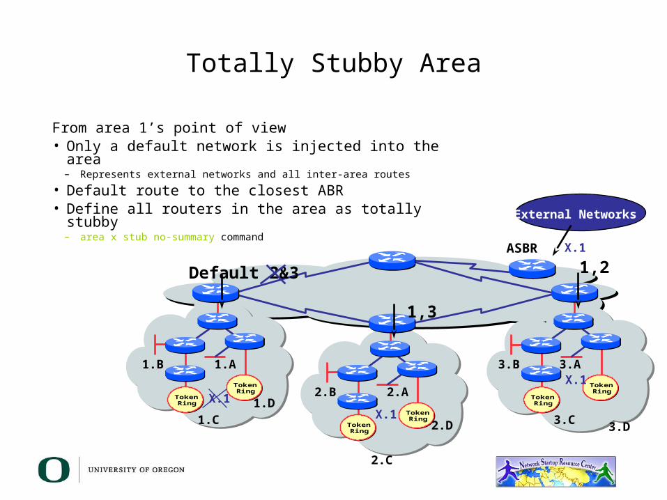
Totally Stubby Area
From area 1’s point of view• Only a default network is injected into the area
– Represents external networks and all inter-area routes
• Default route to the closest ABR• Define all routers in the area as totally stubby
– area x stub no-summary commandASBR
External Networks
1.A
1.C
1.B
1.D TokenRing
TokenRing
3.C
3.B
2.A
Default 2&3
1,3
1,2X.1
X.1
X.1X.1
2.D
2.C
2.B
3.A
3.D

TokenRing
TokenRing
TokenRing
TokenRing
Not-So-Stubby Area
• Capable of importing external routes in a limited fashion
• Type-7 LSAs carry external information within an NSSA
• NSSA border routers translate selected type-7 LSAs into type -5 external network LSAs
ASBR
External Networks
1.A
1.C
1.B
1.D TokenRing
TokenRing
3.C
3.B
2.A
Default 2&3
1,3
1,2X.1
X.1, X.2
X.1, X.2X.1
2.D
2.C
2.B
3.A
3.DExternalNetworks X.2

Addressing
Area 1Network 131.108.0.0Subnets 17-31Range 255.255.240.0
Area 2Network 131.108.0.0Subnets 33-47Range 255.255.240.0
area 3Network 131.108.0.0Subnets 49-63Range 255.255.240.0
Area 0Network 192.117.49.0Range 255.255.255.0
Try to assign contiguous subnet ranges to facilitate summarization

Summary
• Scalable OSPF Network Design– Area hierarchy– Stub areas– Contiguous addressing– Route summarization
OSPF Design Service Provider Networks
BackboneRouter
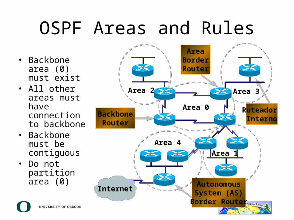
OSPF Areas and Rules• Backbone area
(0) must exist• All other areas
must have connection to backbone
• Backbone must be contiguous
• Do not partition area (0) Area 1
Area 4
Area 0
Area 2 Area 3
Ruteador Interno
AreaBorderRouter
AutonomousSystem (AS)
Border Router
Internet
OSPF Design• Figure out your addressing first – OSPF
and addressing go together– The objective is to maintain a small link-state
DB– Create address hierarchy to match the
network topology– Separate blocks for infrastructure, customer
interfaces, customers, etc.

OSPF Design
• Examine the physical topology– Is it meshed or hub-and-spoke (star)
• Try to use as Stubby an area as possible– It reduces overhead and LSA counts
• Push the creation of a backbone– Reduces mesh and promotes hierarchy

OSPF Design
• One SPF per area, flooding done per area– Try not to overload the ABRs
• Different types of areas do different flooding– Normal areas– Stub areas– Totally stubby (stub no-summary)– Not so stubby areas (NSSA)
OSPF Design
• Redundancy– Dual links out of each area – using metrics (cost) for traffic
engineering– Too much redundancy …
• Dual links to backbone in stub areas must be the same – otherwise sub-optimal routing will result
• Too much redundancy in the backbone area without good summarization will affect convergence in the area 0
OSPF for ISPs
• OSPF features you should consider:– OSPF logging neighbor changes– OSPF reference cost– OSPF router ID command– OSPF Process Clear/Restart
OSPF Best Common Practices – Adding Networks

OSPF – Network Aggregation
• BCP – Individual OSPF network statement for each infrastructure link– Have separate IP address blocks for
infrastructure and customer links– Use IP unnumbered interfaces or
BGP to carry /30 to customers– OSPF should only carry infrastructure
routes in an ISP’s network
OC12c
OC12c
Customer Connections
OC48
ISP Backbone

OSPF – Adding Networks
• Redistribute connected subnet– Works for all connected interfaces on the
router but sends networks as external types-2s – which are not summarized• router ospf 100• redistribute connected subnets
• Not recommended

OSPF – Adding Networks
• Specific network statements– Each interface requires an OSPF network
statement. Interfaces that should not bet broadcasting Hello packets need a passive-interface statement• router ospf 100• network 192.168.1.1 0.0.0.3 area 51• network 192.168.1.5 0.0.0.3 area 51• passive interface Serial 1/0
OSPF – Adding Networks
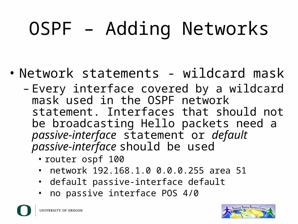
• Network statements - wildcard mask– Every interface covered by a wildcard mask used
in the OSPF network statement. Interfaces that should not be broadcasting Hello packets need a passive-interface statement or default passive-interface should be used• router ospf 100• network 192.168.1.0 0.0.0.255 area 51• default passive-interface default• no passive interface POS 4/0
OSPF – Adding Networks
• The key theme when selecting which method to use is to keep the links-state DB as small as possible– Increases stability– Reduces the amount of information in the
LSAs– Speeds up convergence time
OSPF – UsefulFeatures
OSPF Logging Neighbor Changes
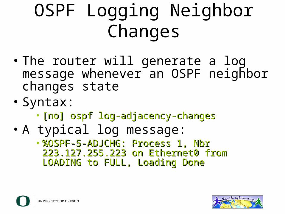
• The router will generate a log message whenever an OSPF neighbor changes state
• Syntax:• [no] ospf log-adjacency-changes[no] ospf log-adjacency-changes
• A typical log message:• %OSPF-5-ADJCHG: Process 1, Nbr %OSPF-5-ADJCHG: Process 1, Nbr
223.127.255.223 on Ethernet0 from LOADING to 223.127.255.223 on Ethernet0 from LOADING to FULL, Loading DoneFULL, Loading Done

Number of State Changes
• The number of state transitions is available via SNMP (ospfNbrEvents) and the CLI:– show ip ospf neighbor [type number] show ip ospf neighbor [type number]
[neighbor-id] [detail][neighbor-id] [detail]• Detail—(Optional) Displays all neighbors given in detail (list
all neighbors). When specified, neighbor state transition counters are displayed per interface or neighbor ID
State Changes (Cont.)
• To reset OSPF related statistics, use the clear ip clear ip ospf countersospf counters EXEC command. – clear ip ospf counters [neighbor [<type clear ip ospf counters [neighbor [<type
number>] [neighbor-id]]number>] [neighbor-id]]
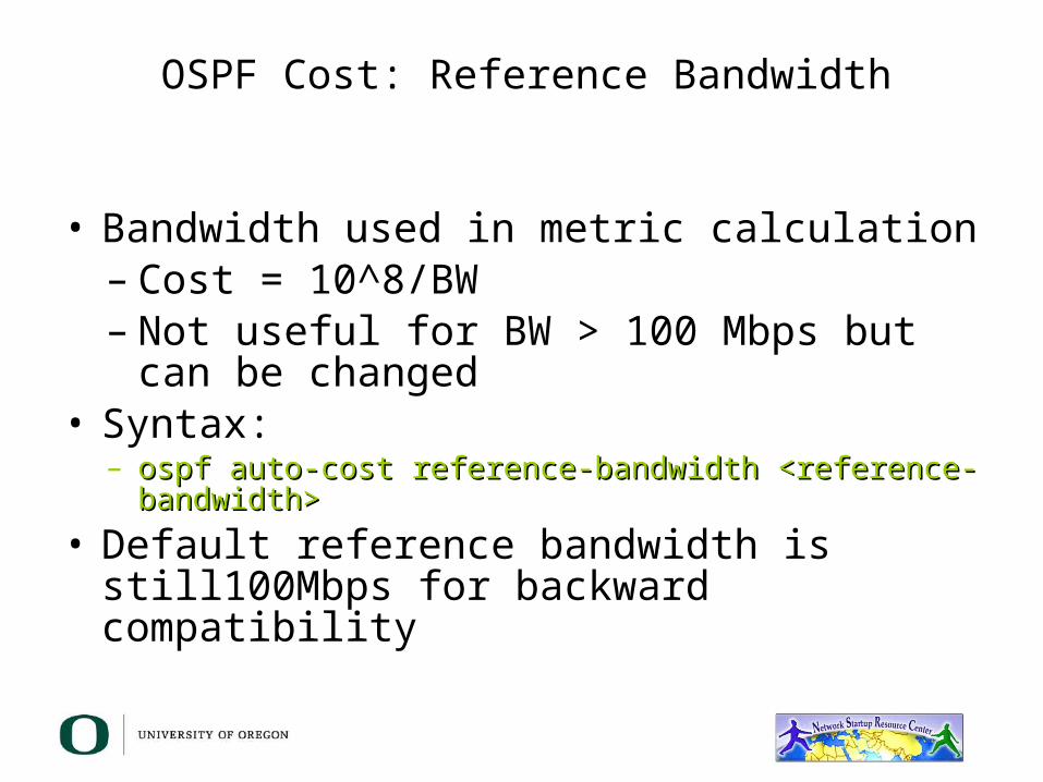
OSPF Cost: Reference Bandwidth
• Bandwidth used in metric calculation– Cost = 10^8/BW– Not useful for BW > 100 Mbps but can be
changed• Syntax:
– ospf auto-cost reference-bandwidth <reference-bandwidth>ospf auto-cost reference-bandwidth <reference-bandwidth>• Default reference bandwidth is still100Mbps for
backward compatibility

OSPF Router ID
• If the loopback interface exists and has an IP address, that is used as the router ID in routing protocols - stability!
• If the loopback interface does not exist, or has no IP address, the router ID is the highest IP address configured – danger!
• Subcommand to manually set the OSPF router ID :– router-id <ip address>
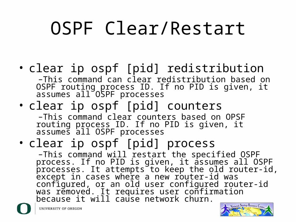
OSPF Clear/Restart
• clear ip ospf [pid] redistribution–This command can clear redistribution based on OSPF routing process ID. If no PID is given, it assumes all OSPF processes
• clear ip ospf [pid] counters–This command clear counters based on OPSF routing process ID. If no PID is given, it assumes all OSPF processes
• clear ip ospf [pid] process–This command will restart the specified OSPF process. If no PID is given, it assumes all OSPF processes. It attempts to keep the old router-id, except in cases where a new router-id was configured, or an old user configured router-id was removed. It requires user confirmation because it will cause network churn.
OSPF Command Summary
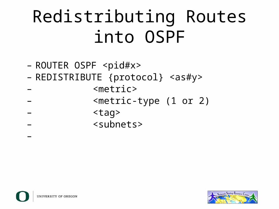
Redistributing Routes into OSPF
– ROUTER OSPF <pid#x>– REDISTRIBUTE {protocol} <as#y>– <metric>– <metric-type (1 or 2)– <tag>– <subnets>–
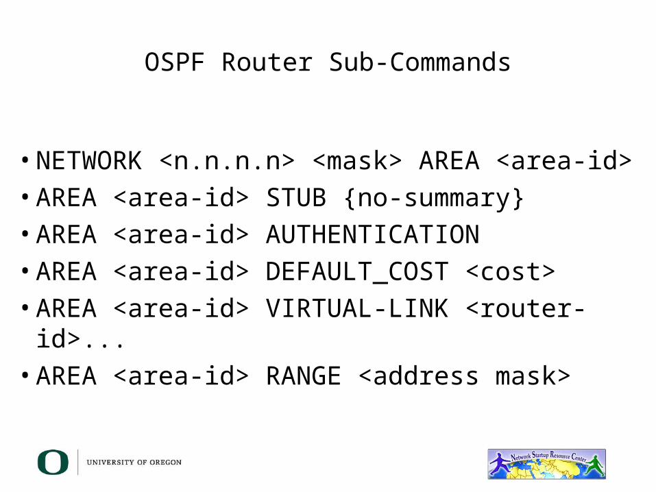
OSPF Router Sub-Commands
• NETWORK <n.n.n.n> <mask> AREA <area-id>• AREA <area-id> STUB {no-summary}• AREA <area-id> AUTHENTICATION• AREA <area-id> DEFAULT_COST <cost>• AREA <area-id> VIRTUAL-LINK <router-id>...• AREA <area-id> RANGE <address mask>
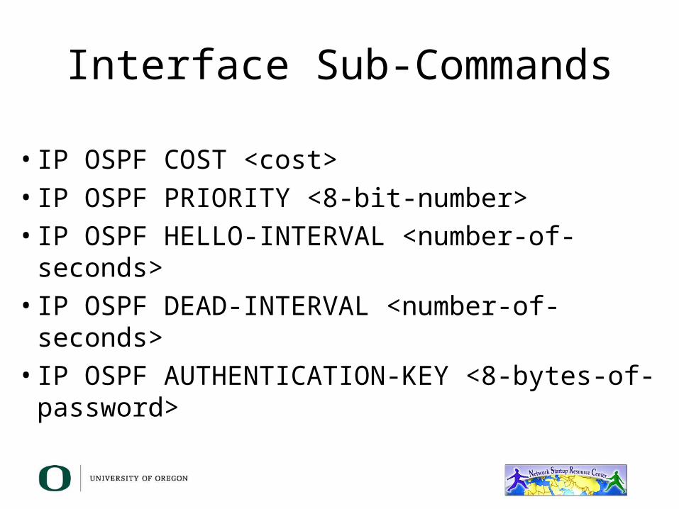
Interface Sub-Commands
• IP OSPF COST <cost>• IP OSPF PRIORITY <8-bit-number>• IP OSPF HELLO-INTERVAL <number-of-seconds>• IP OSPF DEAD-INTERVAL <number-of-seconds>• IP OSPF AUTHENTICATION-KEY <8-bytes-of-
password>