introduction to networking networking hardware€¦ · • repeaters and hubs • switches •...
TRANSCRIPT
Slide 1
Introduction To Networking
Networking Hardware
Slide 2Copyright(c)2006, Groove Systems. All Rights Reserved.
Networking Hardware
• NICs
• Repeaters and Hubs
• Switches
• Routers
• Network Example

Slide 3
NICs
Slide 4Copyright(c)2006, Groove Systems. All Rights Reserved.
NICs
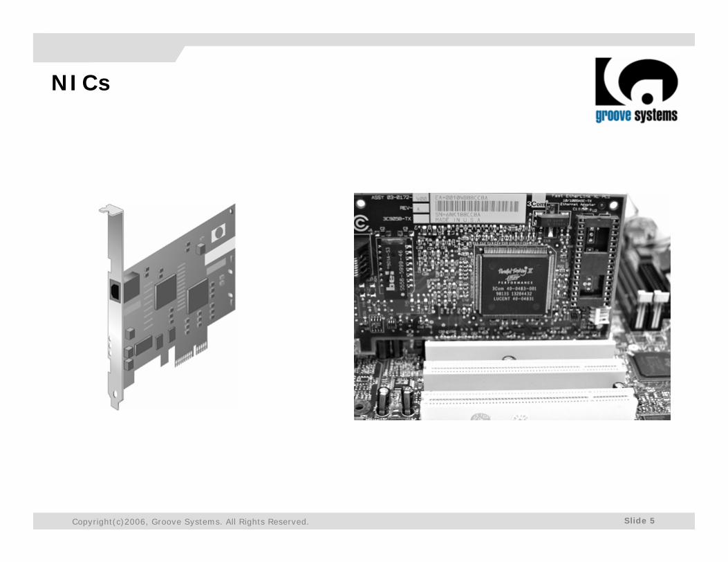
• Network interface cards (also called NICs, network adapters, or network cards) are connectivity devices that enable a workstation, server, printer, or other node to receive and transmit data over the network media
• Nearly all NICs contain a data transceiver, the device that transmits and receives data signals
• NICs belong to both the Physical layer and Data Link layer of the OSI Model, because they apply data signals to the wire and assemble or disassemble data frames
• In addition, they perform the routines that determine which node has the right to transmit data over a network at any given instant
Slide 5Copyright(c)2006, Groove Systems. All Rights Reserved.
NICs

Slide 6
Repeaters and Hubs
Slide 7Copyright(c)2006, Groove Systems. All Rights Reserved.
Repeaters and Hubs
• Repeaters operate in the Physical layer of the OSI Model and, therefore, have no means to interpret the data they retransmit• They simply regenerate a signal over an entire segment
• A repeater contains one input port and one output port, so it is capable only of receiving and repeating a data stream
• Repeaters are suited only to bus topology networks
• The advantage to using a repeater is that it allows you to extend a network inexpensively
Slide 8Copyright(c)2006, Groove Systems. All Rights Reserved.
Repeaters and Hubs
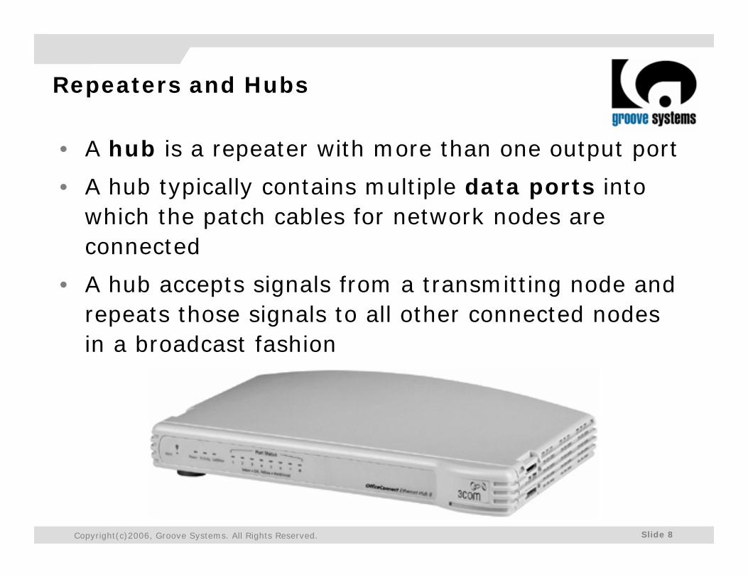
• A hub is a repeater with more than one output port
• A hub typically contains multiple data ports into which the patch cables for network nodes are connected
• A hub accepts signals from a transmitting node and repeats those signals to all other connected nodes in a broadcast fashion
Slide 9Copyright(c)2006, Groove Systems. All Rights Reserved.
Repeaters and Hubs
• All devices connected to a hub share the same amount of bandwidth and the same collision domain
• A collision domain is a logically or physically distinct Ethernet network segment on which all participating devices must detect and accommodate data collisions
• The more nodes participating in the same collision domain, the higher the likelihood of transmission errors and slower performance

Slide 10
Switches
Slide 11Copyright(c)2006, Groove Systems. All Rights Reserved.
Switches
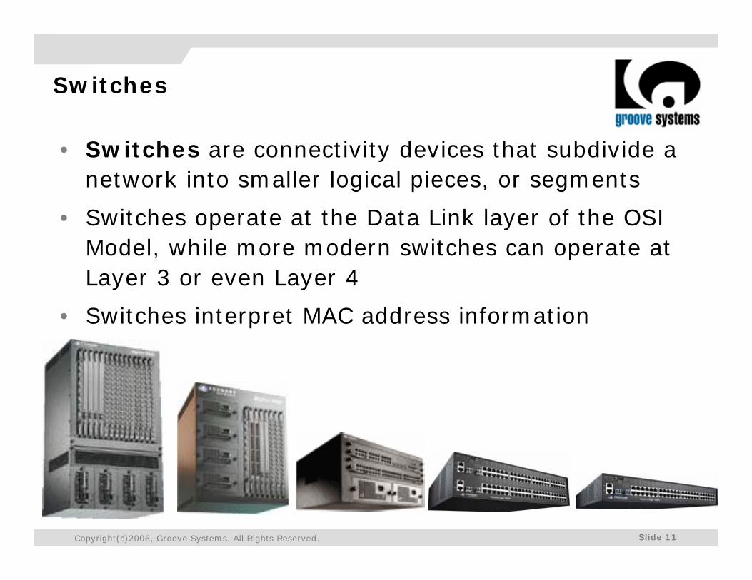
• Switches are connectivity devices that subdivide a network into smaller logical pieces, or segments
• Switches operate at the Data Link layer of the OSI Model, while more modern switches can operate at Layer 3 or even Layer 4
• Switches interpret MAC address information
Slide 12Copyright(c)2006, Groove Systems. All Rights Reserved.
Switches
• Because they have multiple ports, switches can make better use of limited bandwidth
• Each device connected to a switch effectively receives its own dedicated channel to the switch
• From the Ethernet perspective, each dedicated channel represents a collision domain• Because a switch limits the number of devices in a collision
domain, it limits the potential for collisions
• By their nature switches provide better security than many other devices because they isolate one device's traffic from other devices' traffic
Slide 13Copyright(c)2006, Groove Systems. All Rights Reserved.
Switches
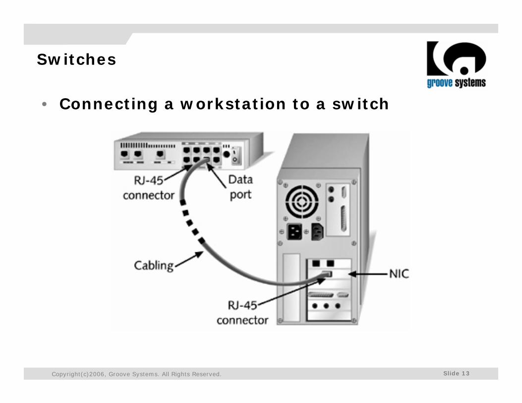
• Connecting a workstation to a switch
Slide 14Copyright(c)2006, Groove Systems. All Rights Reserved.
Switches
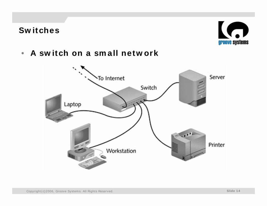
• A switch on a small network
Slide 15Copyright(c)2006, Groove Systems. All Rights Reserved.
Switches
• Switches differ in the method of switching they use:1. Cut-through mode2. Store and forward mode
• Cut-Through Mode• A switch running in cut-through mode reads a frame's
header and decides where to forward the data before it receives the entire packet
• What if the frame becomes corrupt? Because the cut-through mode does not allow the switch to read the frame check sequence (FCS) before it begins transmitting, it can't verify data integrity in that way
Slide 16Copyright(c)2006, Groove Systems. All Rights Reserved.
Switches
• Store and Forward Mode• In store and forward mode, a switch reads the entire
data frame into its memory and checks it for accuracy before transmitting the information
• Although this method is more time-consuming than the cut-through method, it allows store and forward switches to transmit data more accurately
• Store and forward mode switches are more appropriate for larger LAN environments, because they do not propagate data errors

Slide 17
Routers
Slide 18Copyright(c)2006, Groove Systems. All Rights Reserved.
Routers
• A router is a multiport connectivity device that directs data between nodes on a network
• Routers can integrate LANs and WANs running at different transmission speeds and using a variety of protocols
• when a router receives an incoming packet, it reads the packet's logical addressing information• Based on this, it determines to which network the packet
must be delivered• Then it determines the shortest path to that network• Finally it forwards the packet to the next hop in that path
Slide 19Copyright(c)2006, Groove Systems. All Rights Reserved.
Routers
• A router's strength lies in its intelligence
• Not only can routers keep track of the locations of certain nodes on the network, as switches can, but they can also determine the shortest, fastest path between two nodes
• For this reason, and because they can connect dissimilar network types, routers are powerful, indispensable devices on large LANs and WANs
• The Internet, for example, relies on a multitude of routers across the world
Slide 20Copyright(c)2006, Groove Systems. All Rights Reserved.
Routers
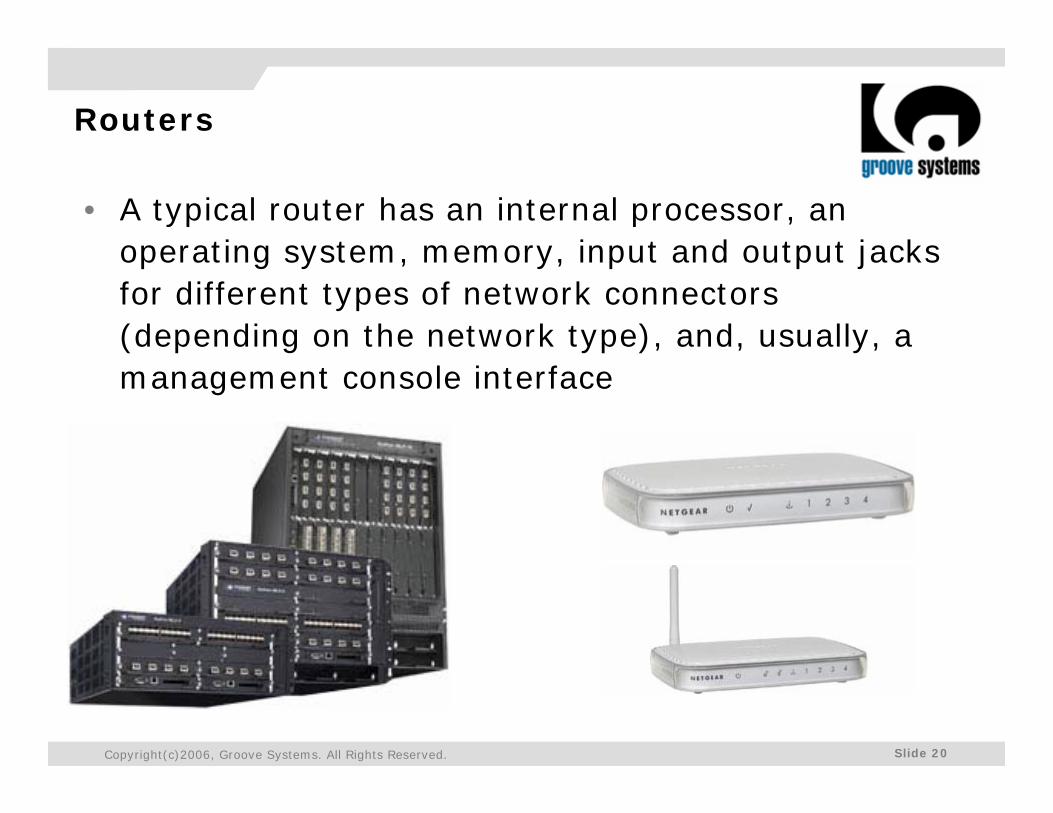
• A typical router has an internal processor, an operating system, memory, input and output jacks for different types of network connectors (depending on the network type), and, usually, a management console interface
Slide 21Copyright(c)2006, Groove Systems. All Rights Reserved.
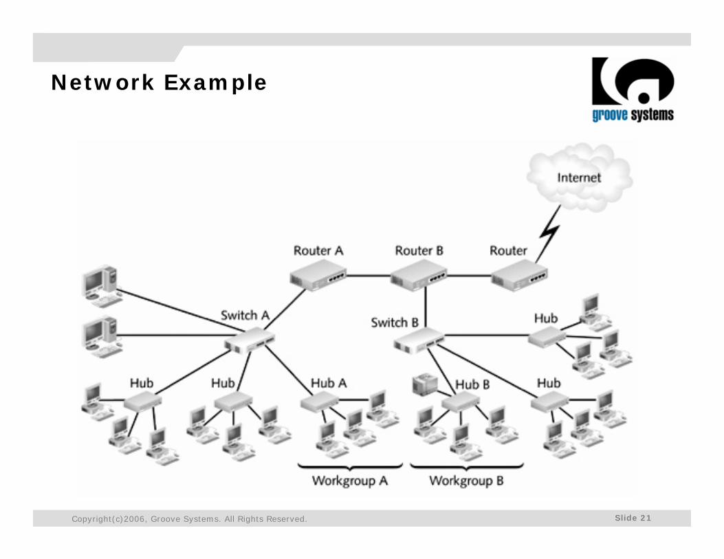
Network Example