introduction to...
TRANSCRIPT
INTRODUCTION TO
MICROPROCESSOR
UNIT 1
LECTURE 1
MICROPROCESSOR
The microprocessor is a multipurpose,
programmable device that accepts digital data as
input, processes it according to instructions stored
in its memory, and provides results as output. It is
an example of sequential digital logic, as it has
internal memory.
2
BLOCK DIAGRAM OF A BASIC
COMPUTER SYSTEM
ROM RAM I/O
interface
I/O
devices
CPU
3
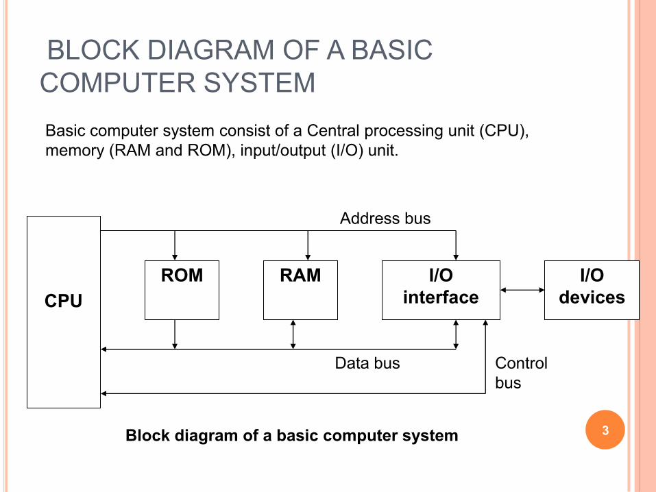
Basic computer system consist of a Central processing unit (CPU),
memory (RAM and ROM), input/output (I/O) unit.
Block diagram of a basic computer system
Address bus
Data bus Control
bus
BASIC COMPONENT OF MICROCOMPUTER
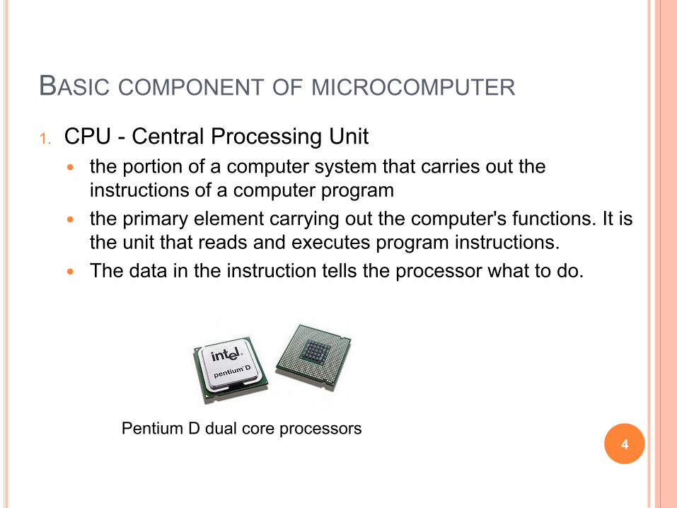
1. CPU - Central Processing Unit
the portion of a computer system that carries out the
instructions of a computer program
the primary element carrying out the computer's functions. It is
the unit that reads and executes program instructions.
The data in the instruction tells the processor what to do.
4 Pentium D dual core processors

2. Memory
Physical devices used to store data or programs (sequences of
instructions) on a temporary or permanent basis for use in an
electronic digital computer.
Computer main memory comes in two principal varieties: random
access memory (RAM) and read only memory(ROM).
RAM can be read and written to anytime the CPU commands it,
but ROM is pre-loaded with data and software that never
changes, so the CPU can only read from it.
ROM is typically used to store the computer's initial start-up
instructions.
In general, the contents of RAM are erased when the power to
the computer is turned off, but ROM retains its data indefinitely.
In a PC, the ROM contains a specialized program called the
BIOS that orchestrates loading the computer's operating system
from the hard disk drive into RAM whenever the computer is
turned on or reset. 5

3. I/O Unit
Input/output (I/O), refers to the communication between an
information processing system (such as a computer), and the
outside world possibly a human, or another information
processing system.
Inputs are the signals or data received by the system, and
Outputs are the signals or data sent from it
Devices that provide input or output to the computer are called
peripherals.
On a typical personal computer , peripherals include input
devices like the keyboard and mouse, and output devices such
as the display and printer . Hard disk drives, floppy disk drives
and optical disc drives serve as both input and output devices.
Computer networking is another form of I/O.
6

EVOLUTION OF MICROPROCESSOR
7
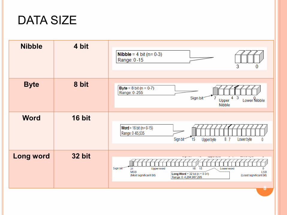
DATA SIZE
Nibble 4 bit
Byte 8 bit
Word 16 bit
Long word
32 bit
8
FETCHING & EXECUTION CYCLES
Fetching Cycles
The fetch cycle takes the instruction required
from memory, stores it in the instruction register,
and
moves the program counter on one so that it
points to the next instruction.
Execute cycle
The actual actions which occur during the
execute cycle of an instruction.
depend on both the instruction itself and the
addressing mode specified to be used to access
the data that may be required. 9
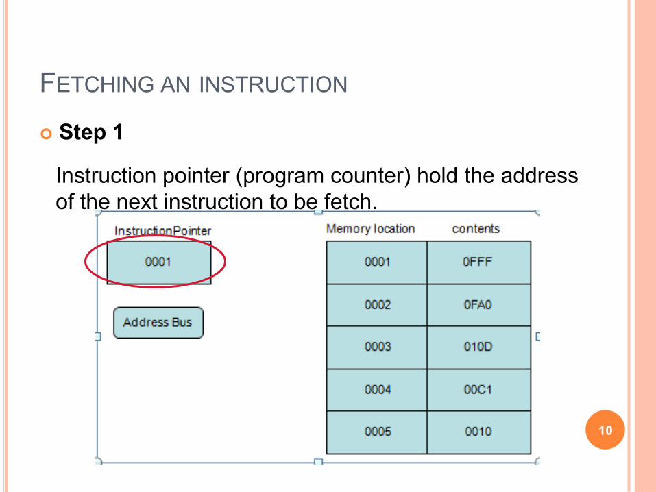
FETCHING AN INSTRUCTION
Step 1
10
Instruction pointer (program counter) hold the address
of the next instruction to be fetch.
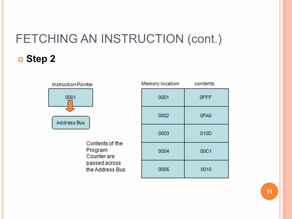
Step 2
11
FETCHING AN INSTRUCTION (cont.)
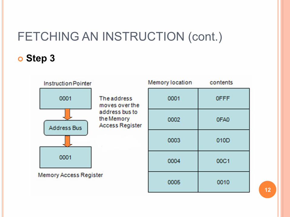
Step 3
12
FETCHING AN INSTRUCTION (cont.)
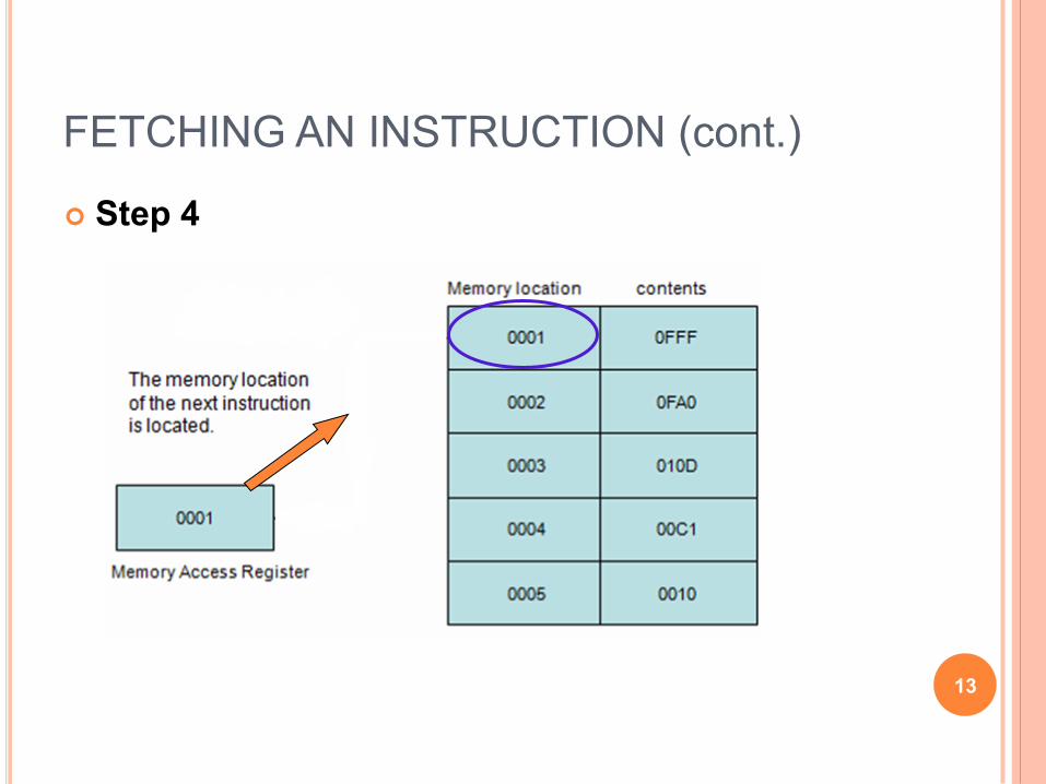
Step 4
13
FETCHING AN INSTRUCTION (cont.)
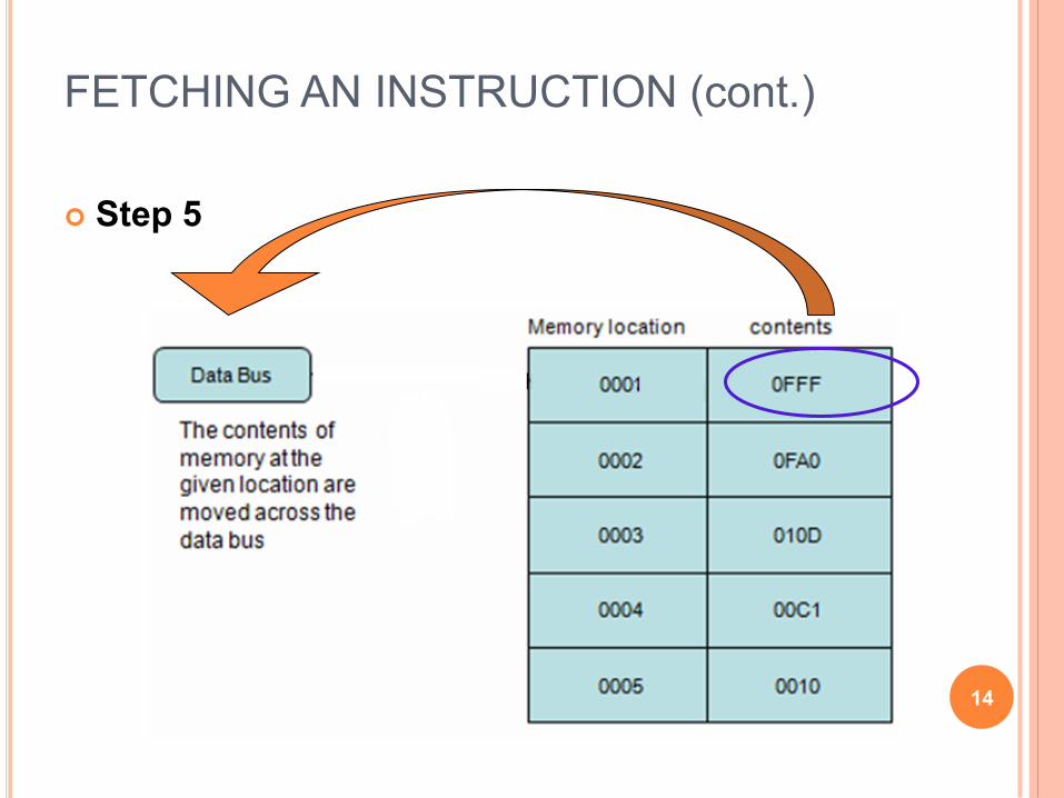
Step 5
14
FETCHING AN INSTRUCTION (cont.)

Step 6
15
FETCHING AN INSTRUCTION (cont.)
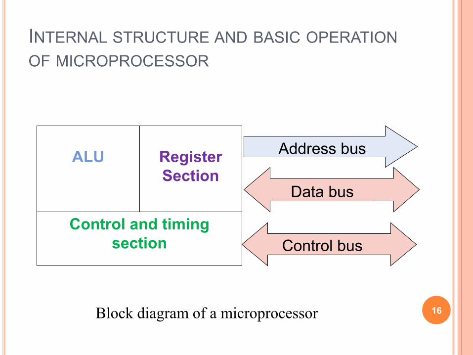
INTERNAL STRUCTURE AND BASIC OPERATION
OF MICROPROCESSOR
ALU
Register
Section
Control and timing
section
Address bus
Data bus
Control bus
16 Block diagram of a microprocessor

CONTROL UNIT
The circuitry that controls the flow of information
through the processor, and coordinates the
activities of the other units within it.
In a way, it is the "brain within the brain", as it
controls what happens inside the processor, which
in turn controls the rest of the PC.
On a regular processor, the control unit performs
the tasks of fetching, decoding, managing
execution and then storing results.
17
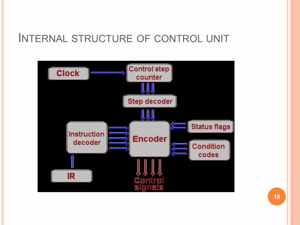
INTERNAL STRUCTURE OF CONTROL UNIT
18
ACCUMULATOR
a register in which intermediate arithmetic and logic
results are stored.
example for accumulator use is summing a list of
numbers.
The accumulator is initially set to zero, then each
number in turn is added to the value in the accumulator.
Only when all numbers have been added is the result
held in the accumulator written to main memory or to
another, non-accumulator, CPU register.
19
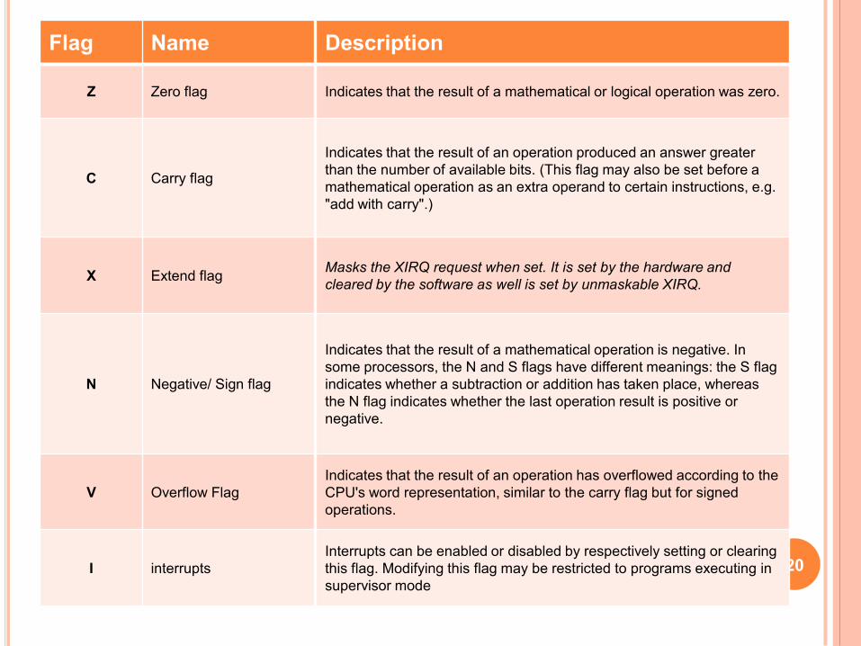
Flag Name
Z Zero flag
C Carry flag
X Extend flag
N Negative/ Sign flag
V Overflow Flag
I interrupts 20
Description
Indicates that the result of a mathematical or logical operation was zero.
Indicates that the result of an operation produced an answer greater
than the number of available bits. (This flag may also be set before a
mathematical operation as an extra operand to certain instructions, e.g.
"add with carry".)
Masks the XIRQ request when set. It is set by the hardware and
cleared by the software as well is set by unmaskable XIRQ.
Indicates that the result of a mathematical operation is negative. In
some processors, the N and S flags have different meanings: the S flag
indicates whether a subtraction or addition has taken place, whereas
the N flag indicates whether the last operation result is positive or
negative.
Indicates that the result of an operation has overflowed according to the
CPU's word representation, similar to the carry flag but for signed
operations.
Interrupts can be enabled or disabled by respectively setting or clearing
this flag. Modifying this flag may be restricted to programs executing in
supervisor mode
PROGRAM COUNTER (PC)
a 16 bit register, used to store the next address of the operation code to be fetched by the CPU.
Not much use in programming, but as an indicator to user only.
Purpose of PC in a Microprocessor
to store address of tos (top of stack)
to store address of next instruction to be executed.
count the number of instructions.
to store base address of the stack. 21
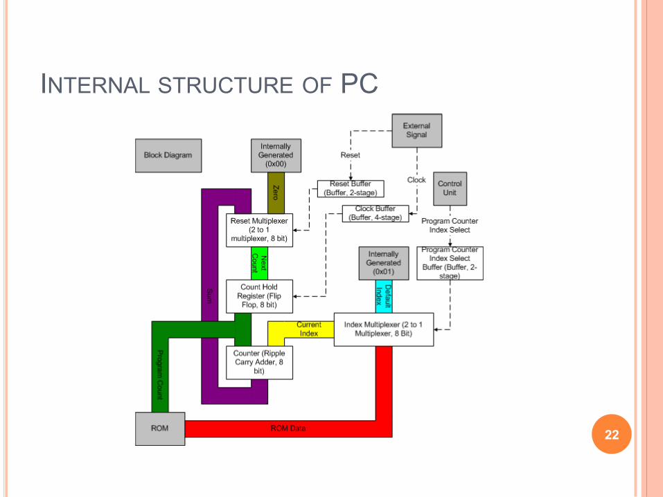
INTERNAL STRUCTURE OF PC
22
STACK POINTER (SP)
The stack is configured as a data structure that grows downward from high memory to low memory.
At any given time, the SP holds the 16-bit address of the next free location in the stack.
The stack acts like any other stack when there is a subroutine call or on an interrupt. ie. pushing the return address on a jump, and retrieving it after the operation is complete to come back to its original location.
23
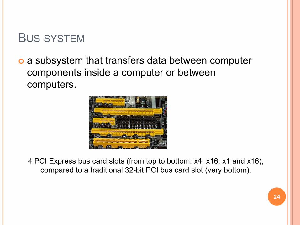
BUS SYSTEM
a subsystem that transfers data between computer
components inside a computer or between
computers.
4 PCI Express bus card slots (from top to bottom: x4, x16, x1 and x16),
compared to a traditional 32-bit PCI bus card slot (very bottom).
24
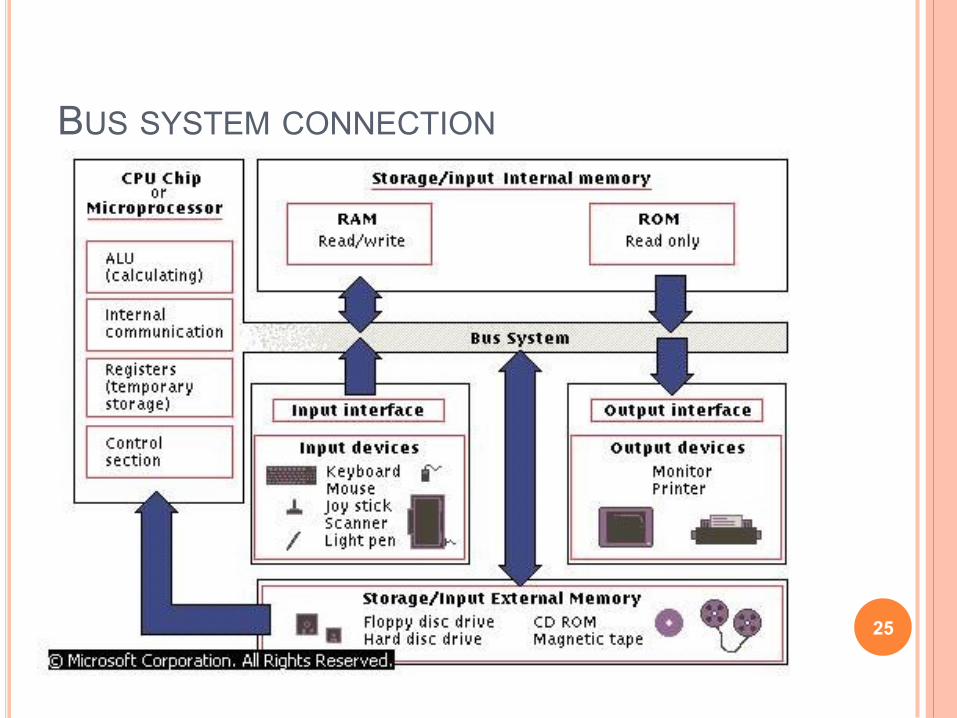
BUS SYSTEM CONNECTION
25
DATA BUS
The data bus is 'bi-directional'
data or instruction codes from memory or
input/output are transferred into the
microprocessor
the result of an operation or computation is sent
out from the microprocessor to the memory or
input/output.
Depending on the particular microprocessor,
the data bus can handle 8 bit or 16 bit data.
26
ADDRESS BUS
The address bus is 'unidirectional', over which the
microprocessor sends an address code to the
memory or input/output.
The size (width) of the address bus is specified by
the number of bits it can handle.
The more bits there are in the address bus, the
more memory locations a microprocessor can
access.
A 16 bit address bus is capable of addressing
65,536 (64K) addresses.
27

CONTROL BUS
The control bus is used by the microprocessor to
send out or receive timing and control signals in
order to coordinate and regulate its operation and
to communicate with other devices, i.e. memory or
input/output.
28
MICRO PROCESSOR CLOCK
Also called clock rate, the speed at which a microprocessor executes instructions. Every computer contains an internal clock that regulates the rate at which instructions are executed and synchronizes all the various computer components.
The CPU requires a fixed number of clock ticks (or clock cycles) to execute each instruction. The faster the clock, the more instructions the CPU can execute per second. Clock speeds are expressed in megahertz (MHz) or gigahertz (GHz).
Some microprocessors are superscalar, which means that they can execute more than one instruction per clock cycle.
Like CPUs, expansion buses also have clock speeds. Ideally, the CPU clock speed and the bus clock speed should be the same so that neither component slows down the other. In practice, the bus clock speed is often slower than the CPU clock speed, which creates a bottleneck. This is why new local buses, such as AGP, have been developed.
29
EXAMPLES OF MICRO PROCESSOR
Intel 8085
Intel 8086
30
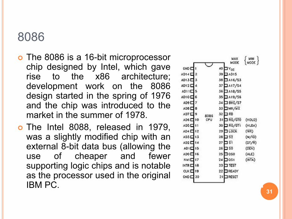
8086
The 8086 is a 16-bit microprocessor chip designed by Intel, which gave rise to the x86 architecture; development work on the 8086 design started in the spring of 1976 and the chip was introduced to the market in the summer of 1978.
The Intel 8088, released in 1979, was a slightly modified chip with an external 8-bit data bus (allowing the use of cheaper and fewer supporting logic chips and is notable as the processor used in the original IBM PC.
31
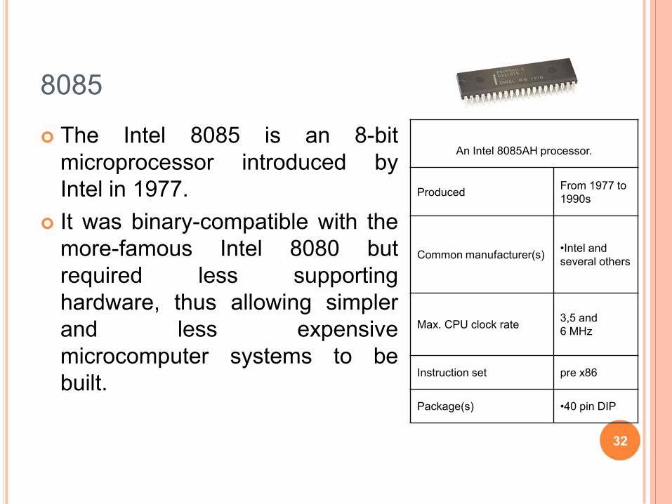
8085
The Intel 8085 is an 8-bit
microprocessor introduced by
Intel in 1977.
It was binary-compatible with the
more-famous Intel 8080 but
required less supporting
hardware, thus allowing simpler
and less expensive
microcomputer systems to be
built.
An Intel 8085AH processor.
Produced From 1977 to
1990s
Common manufacturer(s) •Intel and
several others
Max. CPU clock rate 3,5 and
6 MHz
Instruction set pre x86
Package(s) •40 pin DIP
32