introduction to microcontrollers ii - marquetteperezjc/eece143/handoutup2.pdf · 2001-10-29 ·...
TRANSCRIPT
1
© J. Chris Perez 2001
EECE143 Lecture uP2Introduction to Microcontrollers II
Introduction to Microcontrollers II
brset, brclrIndexed Addressing Example
µp Laboratory #2BUFFALO
Assembling Code
© J. Chris Perez 2001
EECE143 Lecture uP2Introduction to Microcontrollers II
EECE 143 Digital Design ProjectPurpose:To allow students to design their own digital project in order to demonstrate the
utilization of digital design concepts.Examples: Digital Alarm Clock, Traffic Light Simulation, Soda pop machine controller
Scoreboard Display with timersDesign Criteria: If required, all clock sources must be designed and built by students.
You may use IC’s available in the Open Lab.You may use discrete LS or HC ICs as well as GALs.
Grading:Design Proposal 10 DUE: Monday, November 5th in class(Preliminary design diagrams, flowcharts)Design Project 30 Presentations & Reports: Thursday,Dec 6th(Neatness of design, design complexity Making it work)Presentations 60(Visual Aids, Ability to communicate design, Peer, TA and Teacher Evals)Final Report (Writeup) 100(Purpose, Preparation, Experiment Procedure,Design Description, Schematics,
Flowcharts, Code, Future Design Improvements and Considerations)Total 200

2
© J. Chris Perez 2001
EECE143 Lecture uP2Introduction to Microcontrollers II
Digital Design Projects• Digital Alarm Clock
• Digital Temperature Buffer/Storage• Soda Pop Machine with Password for Free Soda• Car Turning Signal Light Controller• Electric Door Lock Control Circuit• Traffic Light Signal Controllers• Digital Tic-Tac-Toe
• Digital Slot Machine• Digital Kitchen Timer• Sports Scoreboard with Timer• Digital Sampler and Playback
© J. Chris Perez 2001
EECE143 Lecture uP2Introduction to Microcontrollers II
Design Project Presentation
• Thursday December 6• 5-10 minutes to present your project and
demonstrate• You will be graded on
– How well you communicate your design– How well you answer questions– Audio/visual aids (Powerpoint presentations,
poster boards…)

3
© J. Chris Perez 2001
EECE143 Lecture uP2Introduction to Microcontrollers II
Design Project Written Report• Due at time of presentation• Typed• Should include the following
– Purpose– Design Description: A module by module description
of your design.– Equations used in your design. Truth Tables…– COMPLETE schematic diagrams, block diagrams– Flow charts and Code ( if applicable)– Testing Procedures: Give a step by step account of how
you test to verify your circuit works.– Future Design Improvements and Conclusion
© J. Chris Perez 2001
EECE143 Lecture uP2Introduction to Microcontrollers II
Design Project Grade Breakdown
• Design Proposal 10• Design Project 30• Presentations 60• Written Report 100Total 200

4
© J. Chris Perez 2001
EECE143 Lecture uP2Introduction to Microcontrollers II
A Look at Appendix A of the HC11 Reference Manual
© J. Chris Perez 2001
EECE143 Lecture uP2Introduction to Microcontrollers II
Load Accumulator
LDA LoaD Accumulator LDA
Operation: AccX ⇐ (M)
Description: Loads the contents of memory into the 8-bit accumulator. The condition codesare set according to the data.
Condition Codes and Boolean Formulae:
S X H I N Z V C- - - - 0 -
N R7Set if MSB of result is set; cleared otherwise
Z R7' • R6' • R5' • R4' • R3' • R2' • R1' • R0'Set if result is $00; cleared otherwise
V 0cleared
Source Form: LDAA (opr); LDAB (opr)
5
© J. Chris Perez 2001
EECE143 Lecture uP2Introduction to Microcontrollers II
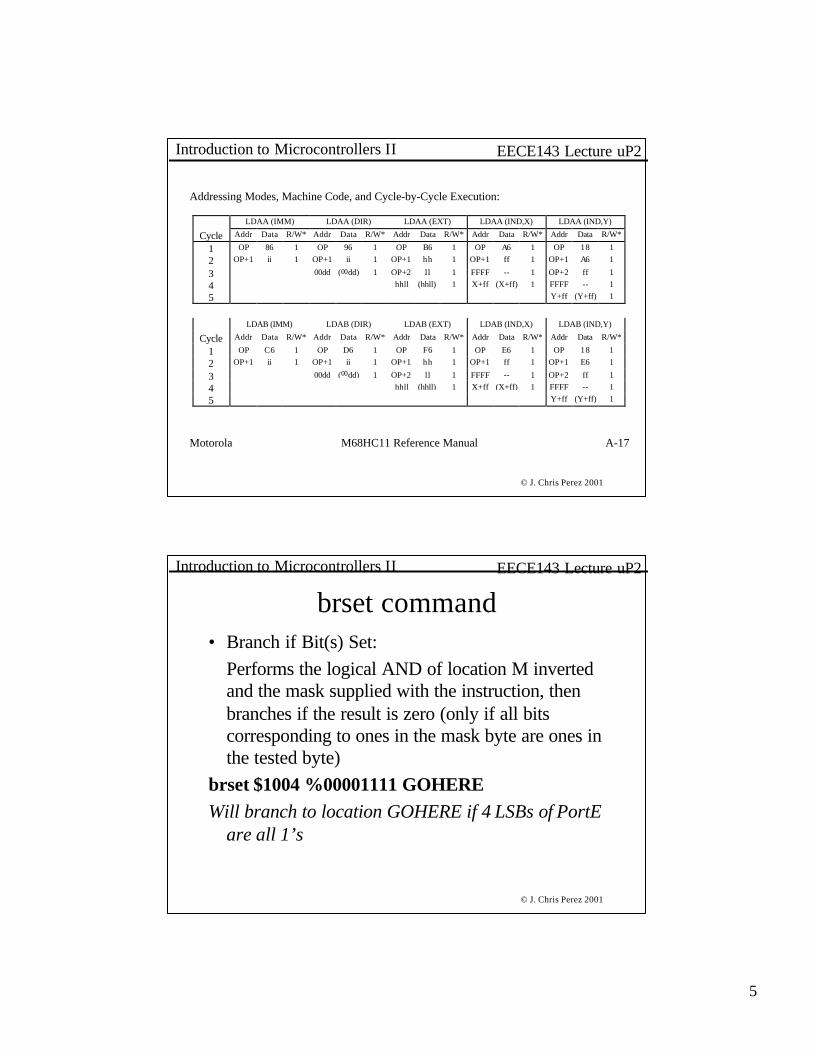
Addressing Modes, Machine Code, and Cycle-by-Cycle Execution:
LDAA (IMM) LDAA (DIR) LDAA (EXT) LDAA (IND,X) LDAA (IND,Y)
Cycle Addr Data R/W* Addr Data R/W* Addr Data R/W* Addr Data R/W* Addr Data R/W*
1 OP 86 1 OP 96 1 OP B6 1 OP A6 1 OP 18 1
2 OP+1 ii 1 OP+1 ii 1 OP+1 hh 1 OP+1 ff 1 OP+1 A6 1
3 00dd (00dd) 1 OP+2 ll 1 FFFF -- 1 OP+2 ff 1
4 hhll (hhll) 1 X+ff (X+ff) 1 FFFF -- 1
5 Y+ff (Y+ff) 1
LDAB (IMM) LDAB (DIR) LDAB (EXT) LDAB (IND,X) LDAB (IND,Y)
Cycle Addr Data R/W* Addr Data R/W* Addr Data R/W* Addr Data R/W* Addr Data R/W*
1 OP C6 1 OP D6 1 OP F6 1 OP E6 1 OP 18 1
2 OP+1 ii 1 OP+1 ii 1 OP+1 hh 1 OP+1 ff 1 OP+1 E6 1
3 00dd (00dd) 1 OP+2 ll 1 FFFF -- 1 OP+2 ff 1
4 hhll (hhll) 1 X+ff (X+ff) 1 FFFF -- 1
5 Y+ff (Y+ff) 1
Motorola M68HC11 Reference Manual A-17
© J. Chris Perez 2001
EECE143 Lecture uP2Introduction to Microcontrollers II
brset command• Branch if Bit(s) Set:
Performs the logical AND of location M inverted and the mask supplied with the instruction, then branches if the result is zero (only if all bits corresponding to ones in the mask byte are ones in the tested byte)
brset $1004 %00001111 GOHEREWill branch to location GOHERE if 4 LSBs of PortE
are all 1’s

6
© J. Chris Perez 2001
EECE143 Lecture uP2Introduction to Microcontrollers II
brclr command• Branch if Bit(s) Clear:
Performs the logical AND of location M and the mask supplied with the instruction, then branches if the result is zero (only if all bits corresponding to ones in the mask byte are zeros in the tested byte)
brset $1004 %00001111 GOHEREWill branch to location GOHERE if 4 LSBs of PortE
are all 0’s
© J. Chris Perez 2001
EECE143 Lecture uP2Introduction to Microcontrollers II
Example: count_br.lst
0001 * COUNT_BR.A110002 * Count pulses at an input.0003 * Two digit BCD output.0004 * Bruce Hoeppner 11/10/920005 * 06/19/94 brset, brclr0006 * NOTE: modifications not tested0007 * NOTE: bset, bclr, brset, brclr instructions0008 * work for direct (page 0) or indexed mode00090010 * Bounceless input at bit0 of PORTE0011 * Output to PORTB0012 * Constants - Hardware dependent0013 1000 REGBASE equ $10000014 0000 _PORTA equ $000015 0004 _PORTB equ $040016 000a _PORTE equ $0a0017 0001 BIT0 equ %000000010018 *************************************************001900200021 c000 org $C000 ;origin in user RAM0022 * Initialize0023 c000 4f MAIN clra0024 c001 ce 10 00 ldx #REGBASE0025 c004 a7 04 staa _PORTB,x ;Initialize Output00260027 * Looking for a POSITIVE EDGE0028 * First: Loop until input = 0 (loop while bit=1)0029 c006 1e 0a 01 fc WAIT0 brset _PORTE,x BIT0 WAIT000300031 * above one line replaces following three,0032 * and it is more clear0033 *WAIT0ldab $100a ;read input0034 * andb #$01 ;mask off 7 MSBs0035 * bne WAIT00036
This program uses the brset brclr commands which check to see if a bit or bits are set or cleared.

7
© J. Chris Perez 2001
EECE143 Lecture uP2Introduction to Microcontrollers II
0037 * Then: Loop until input = 1 (loop while bit=0)0038 c00a 1f 0a 01 fc WAIT1 brclr _PORTE,x BIT0 WAIT100390040 * above one line replaces following three,0041 * and it is more clear0042 *WAIT1 ldab $100A ;read input0043 * andb #$01 ;mask off 7 msbs0044 * beq WAIT100450046 * Only get here if after a +edge at specified bit00470048 *Increment Count (Use adda so daa works)0049 c00e 8b 01 adda #$01 ;increment AccA0050 c010 19 daa ;adjust for BCD00510052 c011 a7 04 staa _PORTB,x ;write to PORTB0053 c013 7e c0 06 jmp WAIT0
When you compare this code with that of count.a11 you will see it is a lot shorter and easier to understand
© J. Chris Perez 2001
EECE143 Lecture uP2Introduction to Microcontrollers II
Using Indexed Addressing in LoopsPORTE equ $100A ;Set definition for PORTEBUFFALO equ $e00a ;Set definition for BUFFALO
org $c000 ;Store program at $c000ldx #$D000 ;load initial value of x register
READ ldaa PORTE ; load value into AccAstaa 0,x ; store value of AccA into memory locationinx ;Increment Register xcmpx #$D00A ;Is x Register = $D00A?blt READ ;If less than get another valuejmp BUFFALO ; If it is, end programend

8
© J. Chris Perez 2001
EECE143 Lecture uP2Introduction to Microcontrollers II
AccA
IndexX
D000D001D002D003
D009D00A
$00 $100A
© J. Chris Perez 2001
EECE143 Lecture uP2Introduction to Microcontrollers II
AccA
IndexX $D000
D000D001D002D003
D009D00A
$00 $100A
ldx #$D000 : Loads Index Register X with $D000 immediate mode

9
© J. Chris Perez 2001
EECE143 Lecture uP2Introduction to Microcontrollers II
AccA
IndexX
$00
$D000
D000D001D002D003
D009D00A
$00 $100A
ldaa PORTE : loads Acca with the contents of PORTE ($100A)
© J. Chris Perez 2001
EECE143 Lecture uP2Introduction to Microcontrollers II
AccA
IndexX
$00
$D000
$00 D000D001D002D003
D009D00A
$00 $100A
staa 0,x ;Puts the contents of AccA into the memory location [D000 + 0]

10
© J. Chris Perez 2001
EECE143 Lecture uP2Introduction to Microcontrollers II
AccA
IndexX
$00
$D001
$00 D000D001D002D003
D009D00A
$00 $100A
inx : increments the Index register X
© J. Chris Perez 2001
EECE143 Lecture uP2Introduction to Microcontrollers II
AccA
IndexX
$00
$D001
$00 D000D001D002D003
D009D00A
$00 $100A
cmpx #$D00A : compares the contents of index register X with $D00A immediate mode
=$D00A?If less than, it branches back to READ, otherwise jmp BUFFALO

11
© J. Chris Perez 2001
EECE143 Lecture uP2Introduction to Microcontrollers II
AccA
IndexX
$00
$D001
D000D001D002D003
D009D00A
$00 $100A
ldaa PORTE : loads Acca with the contents of PORTE ($100A)
© J. Chris Perez 2001
EECE143 Lecture uP2Introduction to Microcontrollers II
AccA
IndexX
$00
$D001
$00$00
D000D001D002D003
D009D00A
$00 $100A
staa 0,x ;Puts the contents of AccA into the memory location [D001 + 0]

12
© J. Chris Perez 2001
EECE143 Lecture uP2Introduction to Microcontrollers II
AccA
IndexX
$00
$D002
$00$00
D000D001D002D003
D009D00A
$00 $100A
inx : increments the Index register X
© J. Chris Perez 2001
EECE143 Lecture uP2Introduction to Microcontrollers II
AccA
IndexX
$00
$D001
$00$00
D000D001D002D003
D009D00A
$00 $100A
cmpx #$D00A : compares the contents of index register X with $D00A immediate mode
=$D00A?If less than, it branches back to READ, otherwise jmp BUFFALO

13
© J. Chris Perez 2001
EECE143 Lecture uP2Introduction to Microcontrollers II
Guide to A11 FilesPORTB equ $1004
org $C000MAIN clra
staa PORTBWAIT0 ldab $100a
andb #$01bne WAIT0
WAIT1 LDAB $100aandb #$01beq WAIT1adda #$01daastaa $1004jmp WAIT0
;constant declarations should be put before the org statement;org <address to store program>;labels and constants should start in column 1, all other
statements should be tabbed to the right;Default is decimal, use $ for HEX or % for binary;Anything after a “;” or a * is a comment
© J. Chris Perez 2001
EECE143 Lecture uP2Introduction to Microcontrollers II
AS11 Common Mistakessee page 9-23
• Missing “#” Motorola defaults to direct or extended addressing mode.• Using signed branches on unsigned data. AS11 has both signed and unsigned
conditional branches. Unsigned (BHI BLO BHS BLS) Signed (BGT BLTBGE BLE)
• Flow charts drawn after code is written. Know what you want to do before you try to write the code.
• Missing a “$”. AS11 defaults to decimal. NOTE: BUFFALO only allows HEX. No “$” is needed when using the onboard assembler ASM.
• Loading a 16-bit value into an 8-bit location or vice versa.• Improper ending for embedded code. Use (in)finite loop or jump to
BUFFALO.• On reads: high byte first, low byte second.• Errors when pushing and pulling from stack.• Memory usage• high byte AccD == AccA, low byte AccD == AccB

14
© J. Chris Perez 2001
EECE143 Lecture uP2Introduction to Microcontrollers II
Code Size and Execution Time0001 * IndStor.a110002 * J. Chris Perez0003 * Program uses indexed registering to loop0004 * through a set of instructions0005 * to increment value located0006 * in AccA and store result in consecutive0007 * Memory locations0008 0009 c000 org $c000 ;Set location of program in memory0010 c000 4f clra ;Clear Accumulator A0011 c001 ce d0 00 ldx #$d000 ; Load Index X with initial location0012 c004 a7 00 HERE staa 0,x ;Store contents of AccA0013 c006 8b 01 adda #$01 ;Increment A0014 c008 08 inx ;Increment Index X0015 c009 8c d0 0a cpx #$d00a ;Compare to $d00a0016 c00c 2d f6 blt HERE ; If less than, jump to store new value0017 c00e 7e e0 0a jmp $e00a ;Jump to BUFFALO�HERE c004 *0012 0016
© J. Chris Perez 2001
EECE143 Lecture uP2Introduction to Microcontrollers II
0001 * IndStor.a110002 * J. Chris Perez0003 * Program uses indexed registering to loop0004 * through a set of instructions0005 * to increment value located0006 * in AccA and store result in consecutive0007 * Memory locations0008 0009 c000 org $c000 ;Set location of program in memory0010 c000 4f clra ;Clear Accumulator A0011 c001 ce d0 00 ldx #$d000 ; Load Index X with initial location0012 c004 a7 00 HERE staa 0,x ;Store contents of AccA0013 c006 8b 01 adda #$01 ;Increment A0014 c008 08 inx ;Increment Index X0015 c009 8c d0 0a cpx #$d00a ;Compare to $d00a0016 c00c 2d f6 blt HERE ; If less than, jump to store new value0017 c00e 7e e0 0a jmp $e00a ;Jump to BUFFALO�HERE c004 *0012 0016
Program is in C000-C010, therefore the program takes up 17 memory spaces.

15
© J. Chris Perez 2001
EECE143 Lecture uP2Introduction to Microcontrollers II
0001 * INNOT2.A11 Read word, NOT it, Write it0002 * Bruce Hoeppner 01 JAN 940003 * Chris Perez 14 June 20000004 *0005 * Read an 8 -bit word from PortE.0006 * Complement the word.0007 * Write the word to PortB.0008 * Definitions0009 1004 PORTB equ $10040010 e00a BUFFALO equ $e00a0011 *********************************** *********0012 * Load program into 8k user RAM0013 c000 org $C0000014 * Read 8 -bit word fromPortE into AccA0015 c000 b6 10 0a ldaa $100a0016 * Complement the word.0017 c003 43 coma0018 * Write the word to PortB0019 c004 b7 10 04 staa PORTB0020 0021 * Jump back to beginning of program0022 c007 7e e0 0a jmp BUFFALO beginning of program�BUFFALO e00a *0010 0022PORTB 1004 *0009 0019
This program is in C000-C009, therefore the program takes up 10 memory spaces.
© J. Chris Perez 2001
EECE143 Lecture uP2Introduction to Microcontrollers II
0001 * INNOT2.A11 Read word, NOT it, Write it0002 * Bruce Hoeppner 01 JAN 940003 * Chris Perez 14 June 20000004 *0005 * Read an 8 -bit word from PortE.0006 * Complement the word.0007 * Write the word to PortB.0008 * Definitions0009 1004 PORTB equ $10040010 e00a BUFFALO equ $e00a0011 *********************************** *********0012 * Load program into 8k user RAM0013 c000 org $C0000014 * Read 8 -bit word fromPortE into AccA0015 c000 b6 10 0a ldaa $100a0016 * Complement the word.0017 c003 43 coma0018 * Write the word to PortB0019 c004 b7 10 04 staa PORTB0020 0021 * Jump back to beginning of program0022 c007 7e e0 0a jmp BUFFALO beginning of program�BUFFALO e00a *0010 0022PORTB 1004 *0009 0019
This program takes 13 cycles (6.5x10⁻⁶ sec) to execute.
From Appendix A:Instruction addressing mode Cycles
ldaa extended 4 coma inherent 2staa extended 4jmp extended 3
Total: 13
13 cycles/freq = 13 / 2MHz= 6.5x10 -6 sec

16
© J. Chris Perez 2001
EECE143 Lecture uP2Introduction to Microcontrollers II
Laboratory µp2: SoftwarePrelab: Create flowcharts and write code for the following:1. Data Entry – Enter eight 4-bit numbers using a dipswitch (or BCD switch). Read the
number when a button is pressed. Store the numbers in sequential memory locations,start at $D000. Display each number as it is entered.
2. Data Sort —Sort eight 4-bit numbers in memory. (Largest to smallest)3. Data Sum – Compute the sum of eight 4-bit numbers in memory. Display result in
BCD.4. Combine Routines – Combine the functions of 1,2 and 3 into one program. Use 2 bits
of PortA to specify which function to perform.00=Data Entry, 01=Data Sort,10=DataSum, 11=Exit Program
Design Rules:1. Use proper documentation when creating your source code.M68HC11EVB I/O limitations: PortB, PortE, PortA (excluding PA7 and PA3)
Remember for Prelab: Show schematic diagrams for all external hardware designs.
© J. Chris Perez 2001
EECE143 Lecture uP2Introduction to Microcontrollers II
Open your hyperterminal connection to the EVB.Power up your EVB and press the EVB RESET button.Note the contents of the screen:BUFFALO-stands for “Bit User Fast Friendly Aid to Logical Operations”

17
© J. Chris Perez 2001
EECE143 Lecture uP2Introduction to Microcontrollers II
© J. Chris Perez 2001
EECE143 Lecture uP2Introduction to Microcontrollers II
Press Enter. This brings up the BUFFALO prompt > You are ready to use the 68HC11EVB.

18
© J. Chris Perez 2001
EECE143 Lecture uP2Introduction to Microcontrollers II
ASM == on-board assemblerASM address
Displays the assembly language for specified address. User may change the instruction and/or data.Labels may not be used. Instead, use the actual memory location where the label points to. Use your .LST file for help.
Use <CR> to advance to next line of code.Use <CTRL-C> to abort on-board assembly.
© J. Chris Perez 2001
EECE143 Lecture uP2Introduction to Microcontrollers II
19
© J. Chris Perez 2001
EECE143 Lecture uP2Introduction to Microcontrollers II
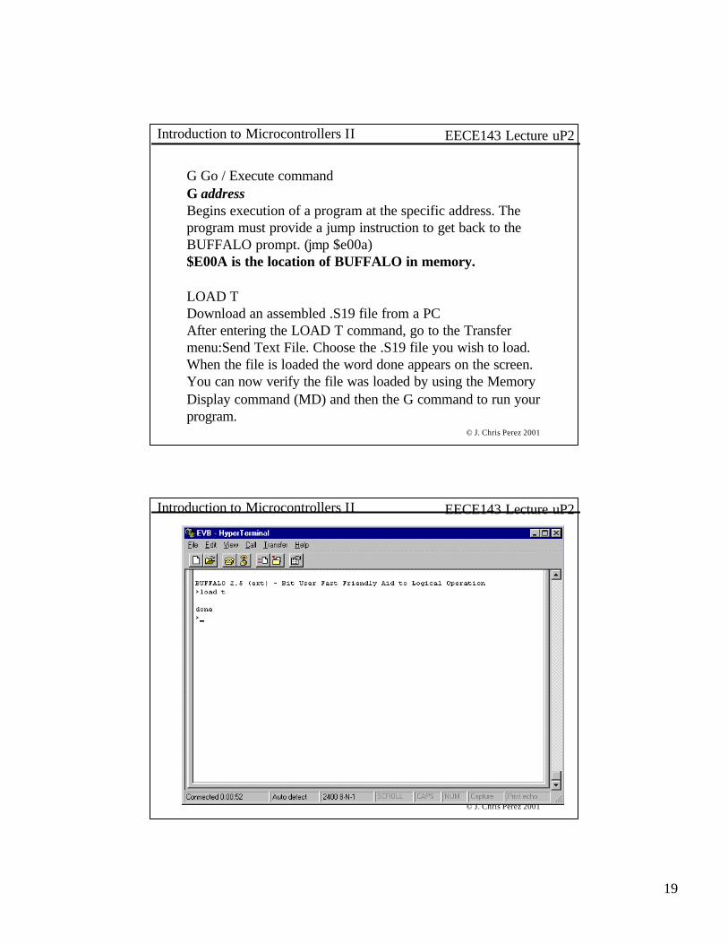
G Go / Execute commandG addressBegins execution of a program at the specific address. The program must provide a jump instruction to get back to the BUFFALO prompt. (jmp $e00a)$E00A is the location of BUFFALO in memory.
LOAD TDownload an assembled .S19 file from a PCAfter entering the LOAD T command, go to the Transfer menu:Send Text File. Choose the .S19 file you wish to load. When the file is loaded the word done appears on the screen. You can now verify the file was loaded by using the Memory Display command (MD) and then the G command to run your program.
© J. Chris Perez 2001
EECE143 Lecture uP2Introduction to Microcontrollers II
20
© J. Chris Perez 2001
EECE143 Lecture uP2Introduction to Microcontrollers II
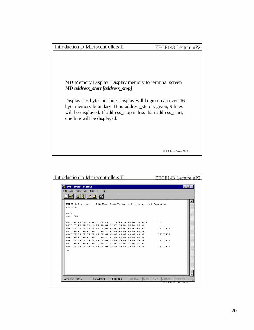
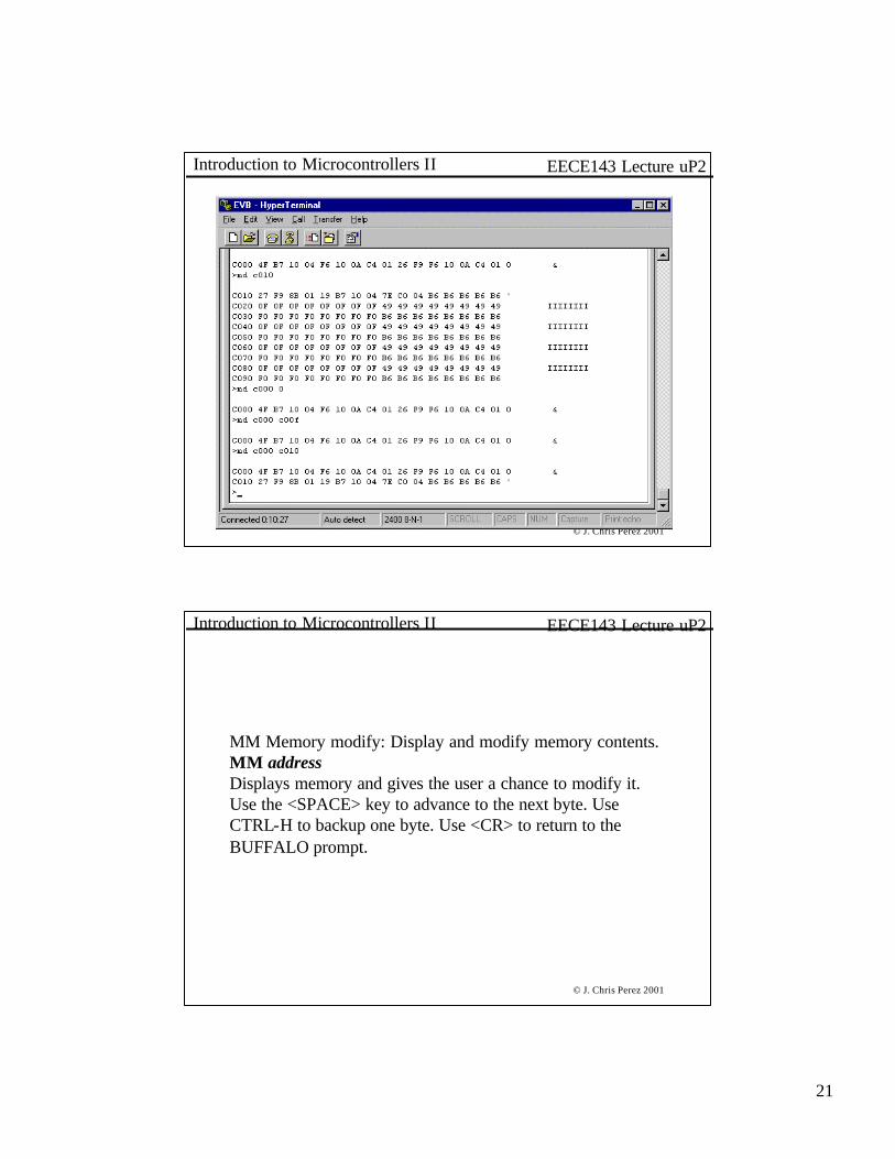
MD Memory Display: Display memory to terminal screenMD address_start [address_stop]
Displays 16 bytes per line. Display will begin on an even 16 byte memory boundary. If no address_stop is given, 9 lines will be displayed. If address_stop is less than address_start, one line will be displayed.
© J. Chris Perez 2001
EECE143 Lecture uP2Introduction to Microcontrollers II
21
© J. Chris Perez 2001
EECE143 Lecture uP2Introduction to Microcontrollers II
© J. Chris Perez 2001
EECE143 Lecture uP2Introduction to Microcontrollers II
MM Memory modify: Display and modify memory contents.MM addressDisplays memory and gives the user a chance to modify it.Use the <SPACE> key to advance to the next byte. Use CTRL-H to backup one byte. Use <CR> to return to the BUFFALO prompt.

22
© J. Chris Perez 2001
EECE143 Lecture uP2Introduction to Microcontrollers II
© J. Chris Perez 2001
EECE143 Lecture uP2Introduction to Microcontrollers II
RM Register Modify: Display and modify 68HC11 registers.RM [p,y,x,a,b,c,s]Displays the contents of the 68HC11’s registers. Also gives the user the chance to modify them.Registers include:
P – program counterY – index register YX – index register XA – Accumulator AB – Accumulator BC – Condition code registerS –Stack pointer

23
© J. Chris Perez 2001
EECE143 Lecture uP2Introduction to Microcontrollers II
© J. Chris Perez 2001
EECE143 Lecture uP2Introduction to Microcontrollers II
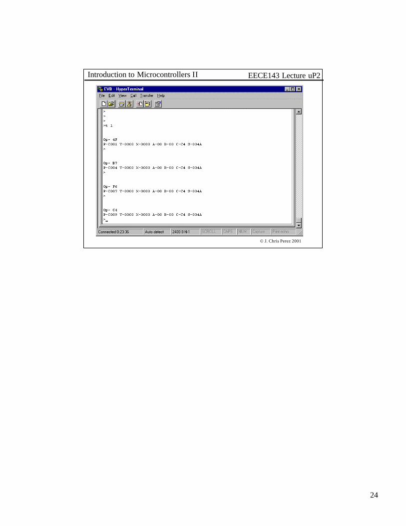
T Trace InstructionsT [n]The trace instruction allows the user to execute a program n instructions at a time. The user must set the program counter to the correct starting address before using the trace command. The machine code for the instruction will be displayed along with the registers after each instructions.
24
© J. Chris Perez 2001
EECE143 Lecture uP2Introduction to Microcontrollers II