introduction to medical imaging mri physicsmueller/teaching/cse577/mriphysics.pdf · introduction...
TRANSCRIPT
Introduction to Medical Imaging
MRI Physics
Klaus Mueller
Computer Science Department
Stony Brook University
The Essential Element for MRI: Hydrogen
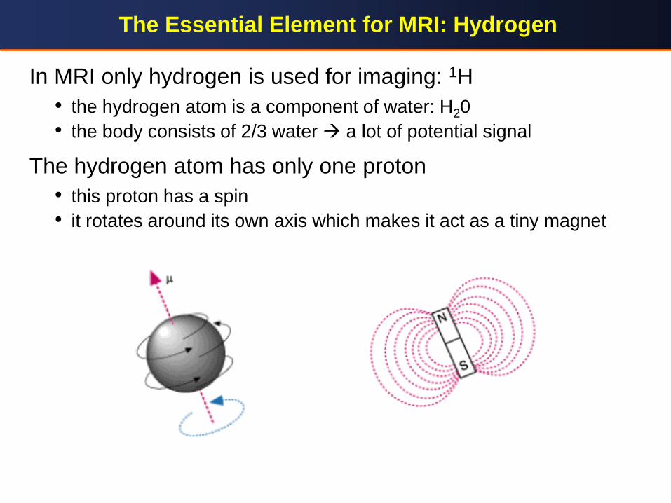
In MRI only hydrogen is used for imaging: 1H
• the hydrogen atom is a component of water: H20
• the body consists of 2/3 water a lot of potential signal
The hydrogen atom has only one proton
• this proton has a spin
• it rotates around its own axis which makes it act as a tiny magnet
Alignment of Protons
parallel
B0
anti-parallel
B0
off
on
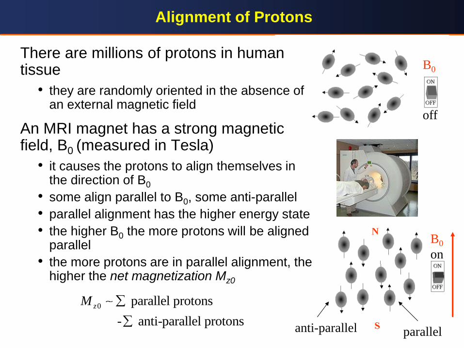
0 parallel protons
- anti-parallel protons
zM
There are millions of protons in human tissue
• they are randomly oriented in the absence of an external magnetic field
An MRI magnet has a strong magnetic field, B0 (measured in Tesla)
• it causes the protons to align themselves in the direction of B0
• some align parallel to B0, some anti-parallel
• parallel alignment has the higher energy state
• the higher B0 the more protons will be aligned parallel
• the more protons are in parallel alignment, the higher the net magnetization Mz0
Larmor Frequency
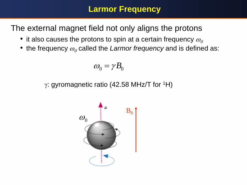
The external magnet field not only aligns the protons
• it also causes the protons to spin at a certain frequency w0
• the frequency w0 called the Larmor frequency and is defined as:
: gyromagnetic ratio (42.58 MHz/T for 1H)
0 0Bw
B0
0w

Measuring the Net Magnetization Mz0
We suspect that Mz0 is related to the amount of hydrogen
• but how do we measure Mz0?
A way to measure a magnetic field is via electromagnetic induction
• moving the magnet in and out of the coil induces an alternating current which can be measured
• the faster we move the magnet, the more current is induced
• the problem with Mz0 is that it is not changing and therefore cannot be measured via induction
Need a way to turn Mz0 into an alternating magnet field
• then the stronger Mz0, the more current would be induced
• also need to perform the measurements orthogonal to B0
Turn Mz0 into such an orthogonal, alternating magnet field by adding a precession component

Proton Spin Precession: Introduction
Equivalent to a spinning top
Now the magnetic field has
• a longitudinal (along B0) component Mz
• a transverse component ( B0) Mxy
Due to the precession Mxy oscillates in a sinusoidal fashion
• can be measured via induction in an RF coil
• will induce a sinusoidal current at frequency w0
• the magnitude is
The highest amount of induction occurs when the flip angle is 90˚
• then Mxy = Mz0 the desired measurement
B0
x
z y
Mxy
Mz RF coil
flip angle a
0 sinxy zM M a
How To Create The Precession
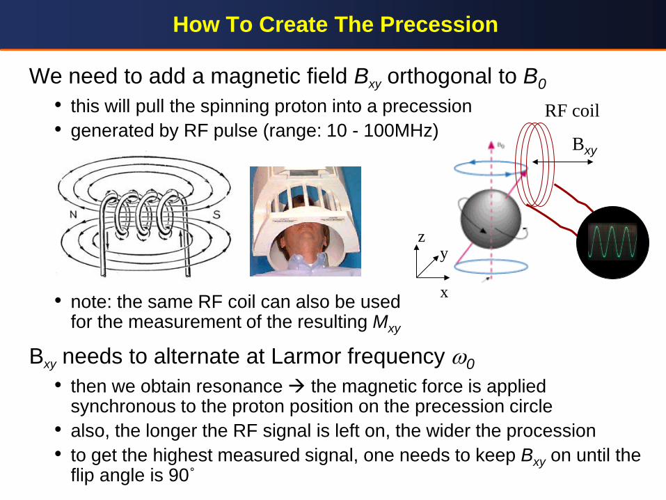
We need to add a magnetic field Bxy orthogonal to B0
• this will pull the spinning proton into a precession
• generated by RF pulse (range: 10 - 100MHz)
• note: the same RF coil can also be used for the measurement of the resulting Mxy
Bxy needs to alternate at Larmor frequency w0
• then we obtain resonance the magnetic force is applied synchronous to the proton position on the precession circle
• also, the longer the RF signal is left on, the wider the procession
• to get the highest measured signal, one needs to keep Bxy on until the flip angle is 90˚
x
z y
Bxy
RF coil
Mz0 90
Bxy
Mz0
More Formally
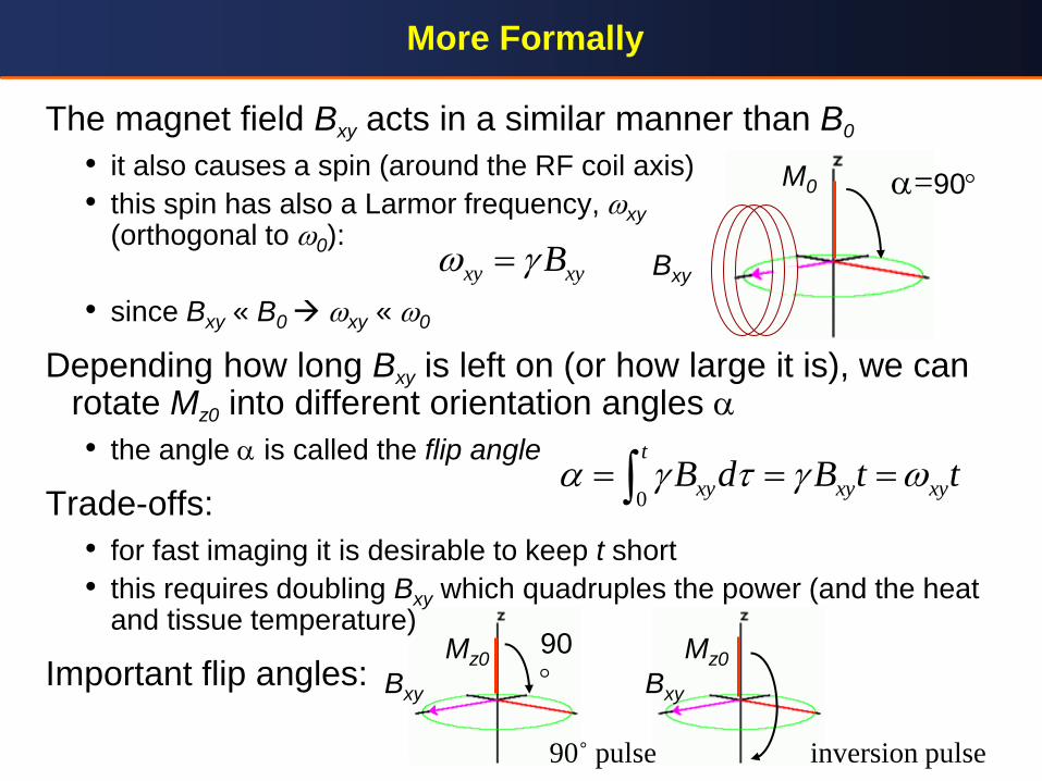
The magnet field Bxy acts in a similar manner than B0
• it also causes a spin (around the RF coil axis)
• this spin has also a Larmor frequency, wxy (orthogonal to w0):
• since Bxy « B0 wxy « w0
Depending how long Bxy is left on (or how large it is), we can rotate Mz0 into different orientation angles a
• the angle a is called the flip angle
Trade-offs:
• for fast imaging it is desirable to keep t short
• this requires doubling Bxy which quadruples the power (and the heat and tissue temperature)
Important flip angles:
xy xyBw
0
t
xy xy xyB d B t ta w
Bxy
90˚ pulse inversion pulse
a=90
Bxy
M0
Relaxation
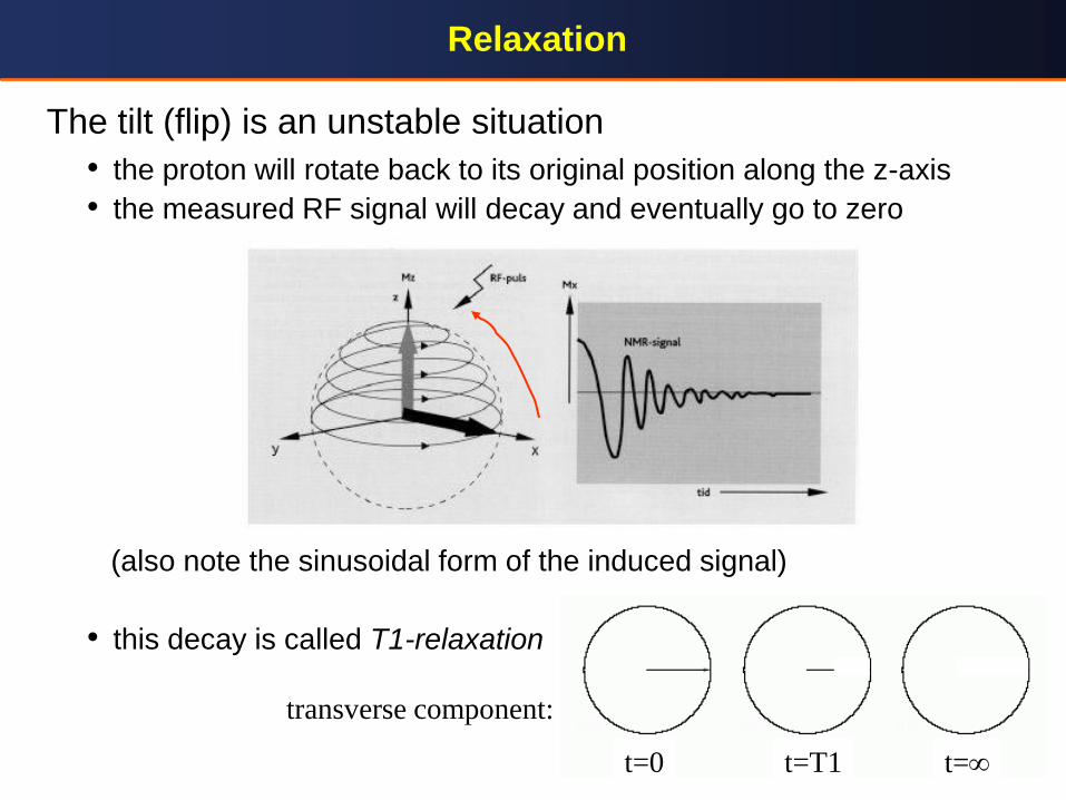
The tilt (flip) is an unstable situation
• the proton will rotate back to its original position along the z-axis
• the measured RF signal will decay and eventually go to zero
(also note the sinusoidal form of the induced signal)
• this decay is called T1-relaxation
transverse component:
t=0 t=T1 t=
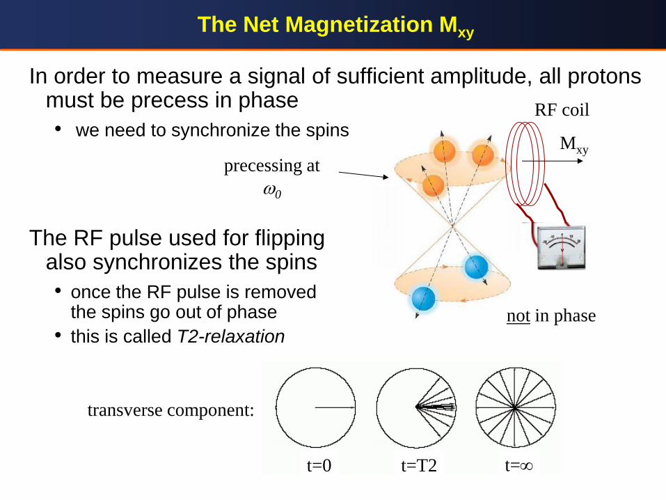
The Net Magnetization Mxy
In order to measure a signal of sufficient amplitude, all protons must be precess in phase
• we need to synchronize the spins
The RF pulse used for flipping also synchronizes the spins
• once the RF pulse is removed the spins go out of phase
• this is called T2-relaxation
Mxy
RF coil
not in phase
t=0 t=T2 t=
transverse component:
precessing at
w0
Spin-Spin Relaxation (T2)
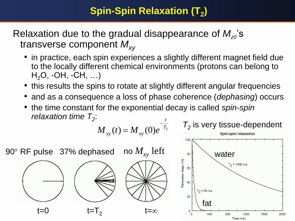
Relaxation due to the gradual disappearance of Mz0’s transverse component Mxy
• in practice, each spin experiences a slightly different magnet field due to the locally different chemical environments (protons can belong to H2O, -OH, -CH, …)
• this results the spins to rotate at slightly different angular frequencies
• and as a consequence a loss of phase coherence (dephasing) occurs
• the time constant for the exponential decay is called spin-spin relaxation time T2:
2( ) (0)
t
T
xy xyM t M e
fat
water 90 RF pulse
T2 is very tissue-dependent
37% dephased no Mxy left
t=T2 t= t=0
Spin-Lattice Relaxation (T1)
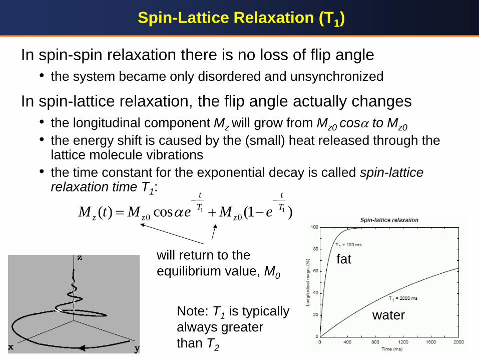
In spin-spin relaxation there is no loss of flip angle
• the system became only disordered and unsynchronized
In spin-lattice relaxation, the flip angle actually changes
• the longitudinal component Mz will grow from Mz0 cosa to Mz0
• the energy shift is caused by the (small) heat released through the lattice molecule vibrations
• the time constant for the exponential decay is called spin-lattice relaxation time T1:
1 1
0 0( ) cos (1 )
t t
T T
z z zM t M e M ea
fat
water
will return to the
equilibrium value, M0
Note: T1 is typically
always greater
than T2
Summary: Energy Absorption and Relaxation
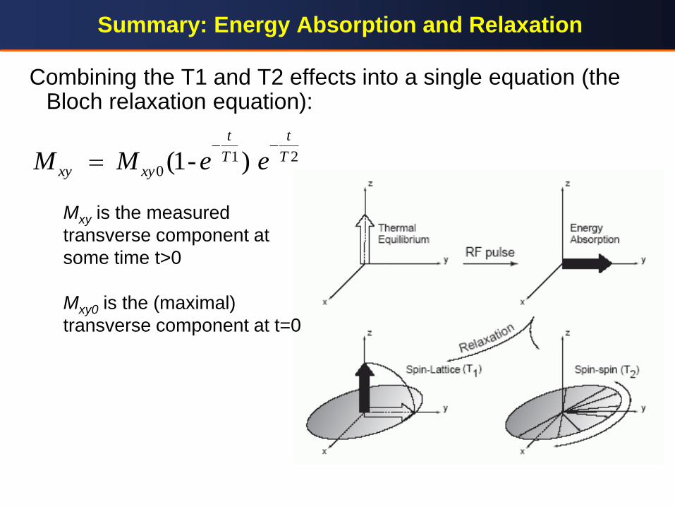
Combining the T1 and T2 effects into a single equation (the Bloch relaxation equation):
1 20 (1- )
t t
T Txy xyM M e e
Mxy is the measured
transverse component at
some time t>0
Mxy0 is the (maximal)
transverse component at t=0
Complex Exponential Representation
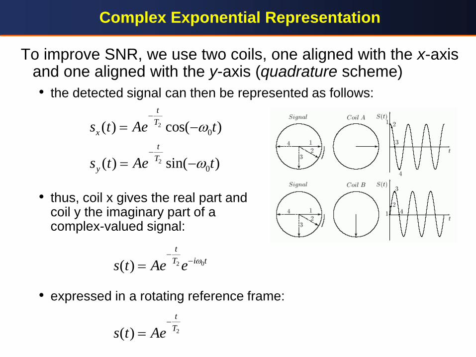
To improve SNR, we use two coils, one aligned with the x-axis and one aligned with the y-axis (quadrature scheme)
• the detected signal can then be represented as follows:
• thus, coil x gives the real part and coil y the imaginary part of a complex-valued signal:
• expressed in a rotating reference frame:
2
2
0
0
( ) cos( )
( ) sin( )
t
T
x
t
T
y
s t Ae t
s t Ae t
w
w
02( )
t
i tTs t Ae ew
2( )
t
Ts t Ae