introduction to logic and combinatorial logic 243 (computer architecture) lecture 4 - introduction...
TRANSCRIPT

COSC 243 (Computer
Architecture)Lecture 4 - Introduction to Logic
and Combinatorial Logic
1
COSC 243
Introduction to Logic
And
Combinatorial Logic

Overview
• This Lecture
– Introduction to Digital Logic
• Gates
• Boolean algebra
– Combinatorial Logic
– Source: Chapter 11 (10th edition)
– Source: J.R. Gregg, Ones and Zeros
• Next Lecture
– Sequential Logic
– Source: Lecture notes
COSC 243 (Computer
Architecture)Lecture 4 - Introduction to Logic
and Combinatorial Logic
2

Internal Assessment
• Data representation test
• During tutorial time in week 3
• 10% of final mark
– No calculators
– Paper provided
– Bring a pen or pencil
COSC 243 (Computer
Architecture)Lecture 4 - Introduction to Logic
and Combinatorial Logic
3

A Bit of History
• Aristotle (384-322 B.C.)
• George Boole (1815-1864)
– Sought to characterize all of human
intelligence in precise symbolic form
– Symbolic logic
COSC 243 (Computer
Architecture)Lecture 4 - Introduction to Logic
and Combinatorial Logic
4

Introduction to Digital Logic
• By digital we mean binary
– True = High = On = 1
– False = Low = Off = 0
COSC 243 (Computer
Architecture)Lecture 4 - Introduction to Logic
and Combinatorial Logic
5

Basic Logic Gates
• Inverter or NOT
• AND
• NAND
• OR
• NOR
• EOR or XOR
COSC 243 (Computer
Architecture)Lecture 4 - Introduction to Logic
and Combinatorial Logic
6

COSC 243 (Computer
Architecture)Lecture 4 - Introduction to Logic
and Combinatorial Logic
7
Inverter or NOT
Q = Ā
A Q
0 1
1 0
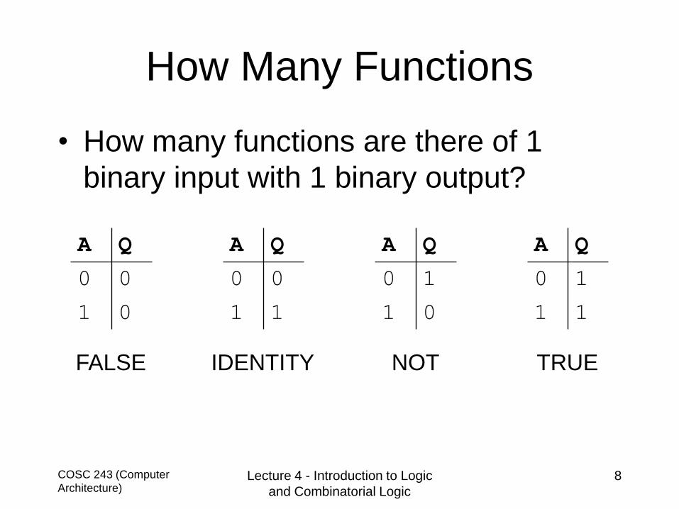
How Many Functions
• How many functions are there of 1
binary input with 1 binary output?
COSC 243 (Computer
Architecture)Lecture 4 - Introduction to Logic
and Combinatorial Logic
8
FALSE IDENTITY NOT TRUE
A Q
0 0
1 0
A Q
0 0
1 1
A Q
0 1
1 0
A Q
0 1
1 1

How Many Functions
• How many functions are there of 2
binary inputs with 1 binary output?
• Which ones are useful?
COSC 243 (Computer
Architecture)Lecture 4 - Introduction to Logic
and Combinatorial Logic
9
A B Q
0 0 0
0 1 0
1 0 1
1 1 1 What is the name of this function?
Is it useful?
B=0 B=1
A=0 0 0
A=1 1 1
Also written

COSC 243 (Computer
Architecture)Lecture 4 - Introduction to Logic
and Combinatorial Logic
10
ANDQ = A · B
Can be extended: Q = A · B · C · . . .
A B Q
0 0 0
0 1 0
1 0 0
1 1 1

COSC 243 (Computer
Architecture)Lecture 4 - Introduction to Logic
and Combinatorial Logic
11
NAND (and then not)Q =𝐀·𝐁
A B Q
0 0 1
0 1 1
1 0 1
1 1 0

COSC 243 (Computer
Architecture)Lecture 4 - Introduction to Logic
and Combinatorial Logic
12
OR
Q = A + B
Can be extended Q = A + B + C + . . .
A B Q
0 0 0
0 1 1
1 0 1
1 1 1

COSC 243 (Computer
Architecture)Lecture 4 - Introduction to Logic
and Combinatorial Logic
13
NOR (or then not)Q = 𝐀 + 𝐁
A B Q
0 0 1
0 1 0
1 0 0
1 1 0

COSC 243 (Computer
Architecture)Lecture 4 - Introduction to Logic
and Combinatorial Logic
14
EOR / XOR (exclusive or)
Q = A B = Ā • B + A • ഥ𝐁
A B Q
0 0 0
0 1 1
1 0 1
1 1 0

Introduction to Combinatorial
Logic• Combinatorial logic circuit - one whose
outputs are dependent only on the inputs
• Assume the outputs respond immediately
• In real circuits, propagation delays must
be considered
– Hence the clock-cycle on your PC
COSC 243 (Computer
Architecture)Lecture 4 - Introduction to Logic
and Combinatorial Logic
15

COSC 243 (Computer
Architecture)Lecture 4 - Introduction to Logic
and Combinatorial Logic
16
Introduction to Combinatorial
Logic (cont)
Combinatorial
Logic
Circuit
i1
in
O1
On
•
•
•
•
•
•Input Output

COSC 243 (Computer
Architecture)Lecture 4 - Introduction to Logic
and Combinatorial Logic
17
Defining a Combinatorial
Circuit• Truth table
– For each of the 2n possible combinations of input
signals, the binary value of each of the m outputs
is listed
• Boolean equations
– Each output signal is expressed as a Boolean
function of its input signals
• Graphical signals
– Interconnection of gates used to implement the
circuit

COSC 243 (Computer
Architecture)Lecture 4 - Introduction to Logic
and Combinatorial Logic
18
1-Bit Half Adder
A
B
Sum S
Carry C
1-bit
half adder
A B C S
0 0 0 0
0 1 0 1
1 0 0 1
1 1 1 0
The 1-bit Half Adder is the
result of adding 2 binary
digits together (A+B)

COSC 243 (Computer
Architecture)Lecture 4 - Introduction to Logic
and Combinatorial Logic
19
1-Bit Half Adder (cont)
S = Ā • B + A • ഥ𝐁= A xor B
C = A • B
= A and B
A B C S
0 0 0 0
0 1 0 1
1 0 0 1
1 1 1 0

Full Adder
Inputs Outputs
A B Cin Cout S
0 0 0 0 0
1 0 0 0 1
0 1 0 0 1
1 1 0 1 0
0 0 1 0 1
1 0 1 1 0
0 1 1 1 0
1 1 1 1 1
COSC 243 (Computer
Architecture)Lecture 4 - Introduction to Logic
and Combinatorial Logic
20

Ripple Carry Adder
COSC 243 (Computer
Architecture)Lecture 4 - Introduction to Logic
and Combinatorial Logic
21

Boolean Precedence
COSC 243 (Computer
Architecture)Lecture 4 - Introduction to Logic
and Combinatorial Logic
22
Operator Precedence
- (NOT) 1
• (AND) 2
+ (OR) 3

COSC 243 (Computer
Architecture)Lecture 4 - Introduction to Logic
and Combinatorial Logic
23
Boolean Algebra
Identity Proposition
A + 0 = A
A + 1 = 1
A • 1 = A
A • 0 = 0
Inverse Proposition
A + Ā= 1
A • Ā= 0

COSC 243 (Computer
Architecture)Lecture 4 - Introduction to Logic
and Combinatorial Logic
24
Boolean Algebra (cont)
Commutative Proposition
A • B = B • A
A + B = B + A
Distributive Proposition
A • (B + C) = (A • B) + (A • C)
A + (B • C) = (A + B) • (A + C)
Law of Involution
ന𝐀 = 𝐀

COSC 243 (Computer
Architecture)Lecture 4 - Introduction to Logic
and Combinatorial Logic
25
Boolean Algebra (cont)
Simplification Theorem
A + A • B = A
A + Ā • B = A + B
(A + B) • (A + C) = A + B • C
A B A+A•B
0 0 0
0 1 0
1 0 1
1 1 1
What will your compiler do when you write
if (a or (a and b))
{
…
}
Is it useful to know this?

Boolean Algebra (cont)
De Morgan's Theorem
The theorem holds for any number of inputs
e.g.
A • B • C .... • X = Ā + ഥ𝐁 + ത𝐂 + ......+ ഥ𝐗
COSC 243 (Computer
Architecture)Lecture 4 - Introduction to Logic
and Combinatorial Logic
26
𝐀 + 𝐁 = Ā • ഥ𝐁
A • B = Ā + ഥ𝐁

COSC 243 (Computer
Architecture)Lecture 4 - Introduction to Logic
and Combinatorial Logic
27
Proof by Truth TableUse first version of De Morgan’s theorem
𝐀 + 𝐁 = Ā • ഥ𝐁
𝐀 𝐁 𝐀 + 𝐁 𝐀 + 𝐁 Ā ഥ𝐁 Ā • ഥ𝐁
0 0 0 1 1 1 1
0 1 1 0 1 0 0
1 0 1 0 0 1 0
1 1 1 0 0 0 0

De Morgan
• Equations of 1-bit half adder requires 2 AND gates, 1
OR gate, and 2 NOT gates
• Inefficient since IC’s contain groups of a single type
of gate
• De Morgan’s theorem states it is possible to convert
a NOR into a NAND and vice versa
COSC 243 (Computer
Architecture)Lecture 4 - Introduction to Logic
and Combinatorial Logic
28

COSC 243 (Computer
Architecture)Lecture 4 - Introduction to Logic
and Combinatorial Logic
29
Equivalent Ways of Drawing
NAND / NOR Gates

Boolean Algebra (cont)
• Actually, De Morgan Said:
– Any Boolean function can be represented as the logical sum
of logical products
• And it gets better because AND and OR can be
described by combinations of NAND gates
– Or alternatively NOR gates
• So all combinatorial circuits can be described using
simply one gate type
– The Apollo Guidance Computer used about 5600 NOR gates
and no other gate types!
COSC 243 (Computer
Architecture)Lecture 4 - Introduction to Logic
and Combinatorial Logic
30

NAND Logic
• NOT
• AND
• OR
COSC 243 (Computer
Architecture)Lecture 4 - Introduction to Logic
and Combinatorial Logic
31

NAND Logic
• NAND
• NOR
• XOR
COSC 243 (Computer
Architecture)Lecture 4 - Introduction to Logic
and Combinatorial Logic
32

COSC 243 (Computer
Architecture)Lecture 4 - Introduction to Logic
and Combinatorial Logic
33
Example:
3-Bit Parity Generator• Add an extra bit to data such that the number
of ones in the data is always odd
• Output - a single output (P)
• Inputs - three inputs labeled A, B, C
Parity
Generator
A
CPB

COSC 243 (Computer
Architecture)Lecture 4 - Introduction to Logic
and Combinatorial Logic
34
Example (cont)
3-Bit Parity Generator• Boolean Equation
– In ‘sum of products form’
• In which rows does p=1
• What are the inputs on those rows
A B C P
0 0 0 0 1
1 0 0 1 0
2 0 1 0 0
3 0 1 1 1
4 1 0 0 0
5 1 0 1 1
6 1 1 0 1
7 1 1 1 0
P = ഥA•ഥB•തC + ഥA•B•C + A•ഥB•C + A•B•തC

COSC 243 (Computer
Architecture)Lecture 4 - Introduction to Logic
and Combinatorial Logic
35
Example (cont)
3-Bit Parity Generator

COSC 243 (Computer
Architecture)Lecture 4 - Introduction to Logic
and Combinatorial Logic
36
7-Segment Decimal Decoder
Example

ROMs
• Combinatorial logic is dependant only
on the n inputs
• There are 2n possible inputs each
numbered from 0 to 2n-1
• The result is a look-up table where the
input specifies a row
• So the logic can be implemented in a
ROM chip (with m outputs)
COSC 243 (Computer
Architecture)Lecture 4 - Introduction to Logic
and Combinatorial Logic
37

Transistor
• Electronic Switch
– B=Base, C=Collector, E=Emitter
• Apply 0v to B and the switch opens
– C is disconnected from E
• Apply +5v to B and the switch closes
– C is connected to E
• In other words, B is the switch that connects
C to E
COSC 243 (Computer
Architecture)Lecture 4 - Introduction to Logic
and Combinatorial Logic
38
B
E
C

NAND Gate
• For Q to be Low (binary 0)
– A and B must be closed
• Otherwise
– If A is open
• +5V flows to Q
– If A is closed but B is open
• +5V flows to Q
– If A and B are closed
• “short circuit Q”
COSC 243 (Computer
Architecture)Lecture 4 - Introduction to Logic
and Combinatorial Logic
39
A
B
Q+5V

Electronic Switch
• How about a switch that we can
– turn on and off with a control line (C)
• Output (Q) = Input (A) iff C = 1
• This is the same as an AND gate
COSC 243 (Computer
Architecture)Lecture 4 - Introduction to Logic
and Combinatorial Logic
40
SwitchA Q
C
A Q
C

• A digital switch in which the select lines (sel1 & sel2)
select between the inputs(I0 I1, I2, I3)
• Imagine I is 4 x 1-bit memory cells and sel selects
the memory location for output to OUT
Multiplexer
COSC 243 (Computer
Architecture)Lecture 4 - Introduction to Logic
and Combinatorial Logic
41
sel1 sel2
I0
I1
I2
I3
OUT
SELECT
INPUTS
I0
I1
I2
I3
00
I0
I1
I2
I3
01
I0
I1
I2
I3
10
I0
I1
I2
I3
11

Multiplexer
COSC 243 (Computer
Architecture)Lecture 4 - Introduction to Logic
and Combinatorial Logic
42
sel1 sel2 OUT
0 0 I0
0 1 I1
1 0 I2
1 1 I3
http://en.wikipedia.org/wiki/Multiplexer

Demultiplexer
• The demultiplexer works in reverse
– One of the outputs (Y0-Y3) is selected (sel1-sel2) for input
• Imagine INPUT is 1-bit value and sel selects where
to store the value
COSC 243 (Computer
Architecture)Lecture 4 - Introduction to Logic
and Combinatorial Logic
43
sel1 sel2
Y3
Y2
Y1
Y0
SELECT
OUTPUT
INPUT
sel1 sel2 OUTPUT
0 0 Y0
0 1 Y1
1 0 Y2
1 1 Y3
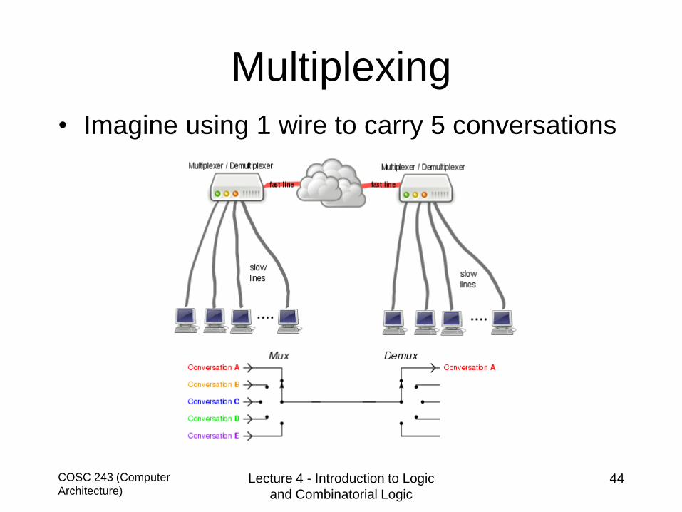
Multiplexing
• Imagine using 1 wire to carry 5 conversations
COSC 243 (Computer
Architecture)Lecture 4 - Introduction to Logic
and Combinatorial Logic
44

COSC 243 (Computer
Architecture)Lecture 4 - Introduction to Logic
and Combinatorial Logic
45
Summary
• Logic gates
– symbols
– truth tables
• Boolean algebra
– Rules
• Equations from truth tables
• Combinatorial logic

Homework
• Draw a half adder using only NAND gates
• Extend your half-adder to a full adder using
only NAND gates
• Draw the circuit for a 3-bit ripple carry adder
• Encode your 3-bit ripple carry adder as a
program (Java / Python) and check it works
• Draw the circuit for a 1-input 2-selector 4-
output demultiplexer
COSC 243 (Computer
Architecture)Lecture 4 - Introduction to Logic
and Combinatorial Logic
46