introduction to logging -while-drilling lwd_presentation .… · - hardware – - 3 large...
TRANSCRIPT
© 2008 Weatherford. All rights reserved.
Drilling Services Technology
Introduction to Logging-While-Drilling

© 2010 Weatherford. All rights reserved.
MWD and LWD
• LWD provides formation evaluation measurements
• MWD provides drilling mechanics and survey measurements
– It also transmits data up hole by mud pulse telemetry
© 2010 Weatherford. All rights reserved.
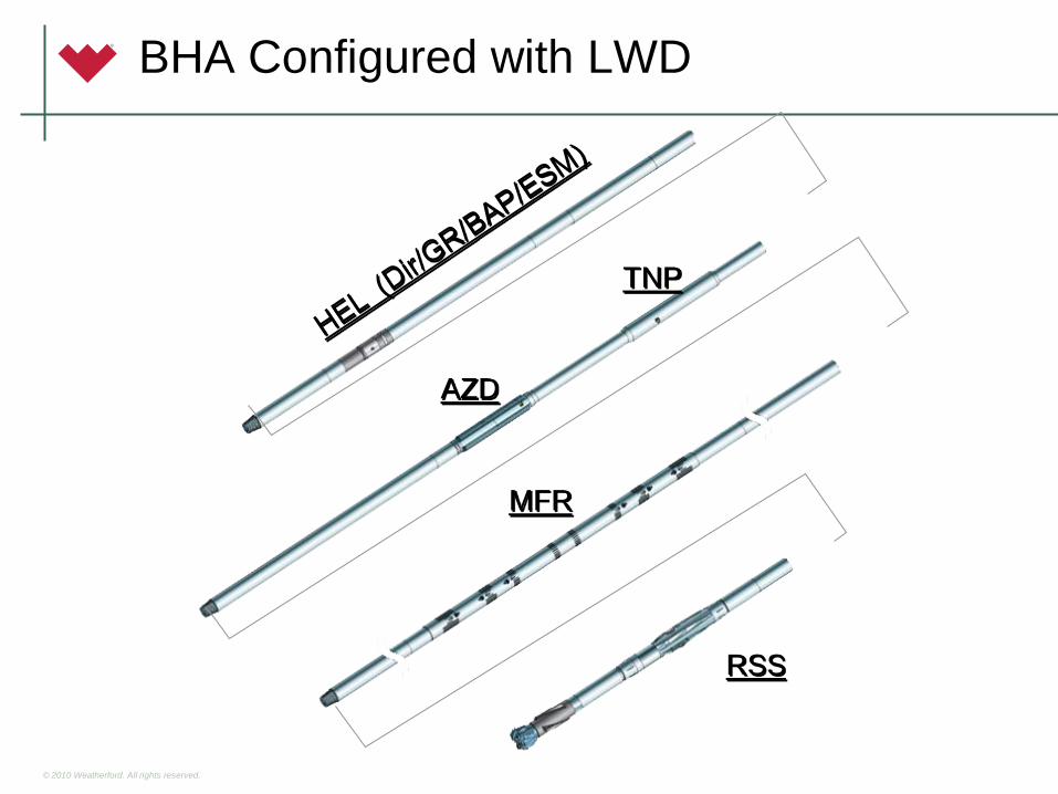
BHA Configured with LWD
RSS
MFR
TNP
AZD

© 2010 Weatherford. All rights reserved.
HEL™ System Components
• Pressure Modulated Telemetry (PMT™) assembly
• ESM Environment Severity Measurement sensor or TVM Total Vibration Monitor
• Dual Battery Module (DBM™) assembly
• High Temperature Azimuthal Gamma Ray (HAGR™) tool
• Bore/Annular Pressure (BAP™) tool
• Integrated Directional Sonde (IDS™) tool

© 2010 Weatherford. All rights reserved.
EMpulse™ MWD system
© 2010 Weatherford. All rights reserved.
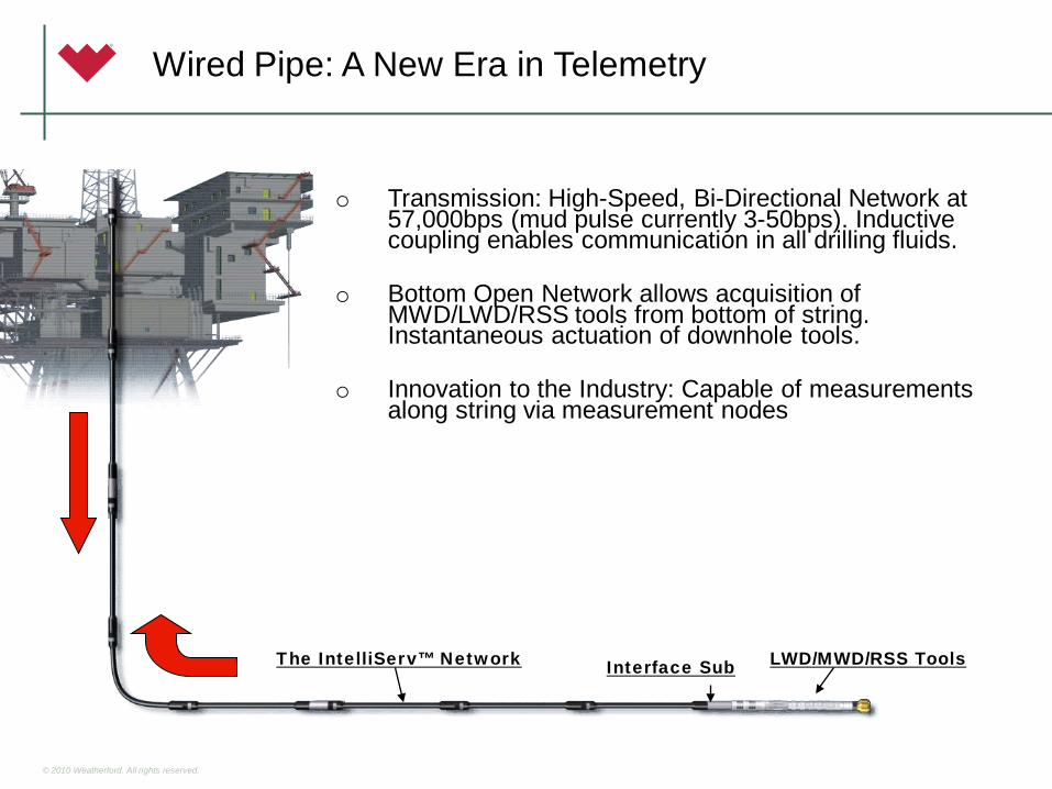
o Transmission: High-Speed, Bi-Directional Network at 57,000bps (mud pulse currently 3-50bps). Inductive coupling enables communication in all drilling fluids.
o Bottom Open Network allows acquisition of MWD/LWD/RSS tools from bottom of string. Instantaneous actuation of downhole tools.
o Innovation to the Industry: Capable of measurements along string via measurement nodes
LWD/MWD/RSS ToolsThe IntelliServ™ Network Interface Sub
Wired Pipe: A New Era in Telemetry
© 2010 Weatherford. All rights reserved.
LWD Sensors
• Gamma Ray
– HAGR – High-Temperature Azimuthal Gamma Ray
– SAGR - Spectral Azimuthal Gamma Ray
• Resistivity - MFR – Multi-Frequency Resistivity
• AZD - Azimuthal Density
• TNP – Thermal Neutron Porosity
• ShockWave Sonic
• PressureWave Formation Tester
© 2010 Weatherford. All rights reserved.
Gamma Ray Introduction
The Gamma Ray Curve:
• Measures the naturally occurring radiation from the rocks surrounding the borehole.
• It’s a passive recording.
• Shales usually exhibit higher levels of radiation than non shale formations.
8

© 2010 Weatherford. All rights reserved.
4-3/4” Insert
10 tubes (5 x 2)
6-3/4” Insert
16 tubes (8 x 2)8-1/4 & 9-1/2” Insert
18 tubes (6 x 3)
High-Temperature Azimuthal Gamma Ray (HAGR)

© 2010 Weatherford. All rights reserved.
HAGR Placement Options
RSS
MFR
TNP
AZD
Middle of the HEL Collar
Bottom of the MFR Collar
Top of the RSS Tool

© 2010 Weatherford. All rights reserved.
1
2
3
45
6
7
8
As the tool rotates, X- and Y-axis magnetometers track the
orientation of each detector tube.
As each gamma ray count is detected, it is placed in one of 8
azimuthal bins, based on the detector position at the time of
detection.
Total, Up/Down, Quadrant, and Octant GR count rates and API values are computed at the end
of each sample period.
HAGR Azimuthal Data Acquisition

© 2010 Weatherford. All rights reserved.
The 8 azimuthally oriented GR
curves…
…are interpolated vertically and circumferentially to produce a
360º borehole image.
Dips are computed from planar features picked
on the image log.

© 2010 Weatherford. All rights reserved. 13

© 2010 Weatherford. All rights reserved.
10 d
eg
20 d
eg30
deg
40 d
eg50
deg
70 d
eg
Bed is dipping 44 deg. to the southeast
“Tail” of the tadpole gives dip direction on a 0-360 azimuth scale.
“Body” of the tadpole gives dip angle (from horizontal) on the 0-90 horizontal grid scale.
Bed is dipping 30 deg. to the southeast

© 2010 Weatherford. All rights reserved.
HAGR Image Across Major Unconformity

© 2010 Weatherford. All rights reserved.
HAGR Summary
• Environment: 180°C (356°F), 30,000 psi
• Tool Sizes: 4-3/4”, 6-3/4”, 8-1/4”, 9-1/2”– Sensor configuration optimized for each tool size
• Output:– Total GR– Up / Down GR– Up / Down / Left / Right quadrant curves– 8-Bin Borehole Image (Real-Time & Recorded)
• Applications:– Correlation, Vsh– Geosteering, Basic structural information
• Can be placed in HEL, MFR, or RSS collars to get close to bit.

© 2010 Weatherford. All rights reserved.
LWD Sensors
• Gamma Ray
– HAGR - High-Temperature Azimuthal Gamma Ray
– SAGR - Spectral Azimuthal Gamma Ray
• Resistivity - MFR – Multi-Frequency Resistivity
• AZD - Azimuthal Density
• TNP – Thermal Neutron Porosity
• ShockWave Sonic
• PressureWave Formation Tester

© 2010 Weatherford. All rights reserved. 18
Spectral Gamma Ray
• Spectral Gamma Ray devices are also “passive” detectors of radioactive gamma ray decay occurring within formations
• Unlike natural gamma devices, the spectral device uses a detector which can distinguish the origin of each gamma ray it detects
• This can be done because potassium, thorium, and uranium each have unique decay spectrums
© 2010 Weatherford. All rights reserved.
Spectral Azimuthal Gamma Ray (SAGR) Tool
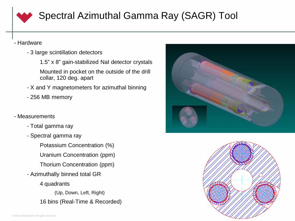
- Hardware
– - 3 large scintillation detectors
• 1.5” x 8” gain-stabilized NaI detector crystals
• Mounted in pocket on the outside of the drill collar, 120 deg. apart
– - X and Y magnetometers for azimuthal binning
– - 256 MB memory
• - Measurements
– - Total gamma ray
– - Spectral gamma ray
• Potassium Concentration (%)
• Uranium Concentration (ppm)
• Thorium Concentration (ppm)
– - Azimuthally binned total GR
• 4 quadrants– (Up, Down, Left, Right)
• 16 bins (Real-Time & Recorded)

© 2010 Weatherford. All rights reserved.

© 2010 Weatherford. All rights reserved.

© 2010 Weatherford. All rights reserved.
Same amount of Potassium
Difference is U, Th

© 2010 Weatherford. All rights reserved.
SAGR in Barnett Shale Horizontal Well

© 2010 Weatherford. All rights reserved. Issued: 8-9-04, Revision: 1, Document owner: Marketing 24
SAGR Applications
The SAGR tool addresses three distinct applications:
• Spectral Gamma Ray Measurement
– Clay typing
– Organic shale evaluation• Uranium associated w/ organic matter
• Clay-content vs. brittleness relationships
• Azimuthal Gamma Ray / Borehole Imaging
– Geosteering and basic structural information
• Fast Logging / High Resolution Gamma Ray Logging
– Count rate ~ 50 times higher than standard LWD GR

© 2010 Weatherford. All rights reserved.
LWD Sensors
• Gamma Ray
– HAGR - High-Temperature Azimuthal Gamma Ray
– SAGR - Spectral Azimuthal Gamma Ray
• Resistivity - MFR – Multi-Frequency Resistivity
• AZD - Azimuthal Density
• TNP – Thermal Neutron Porosity
• ShockWave Sonic
• PressureWave Formation Tester
© 2010 Weatherford. All rights reserved.
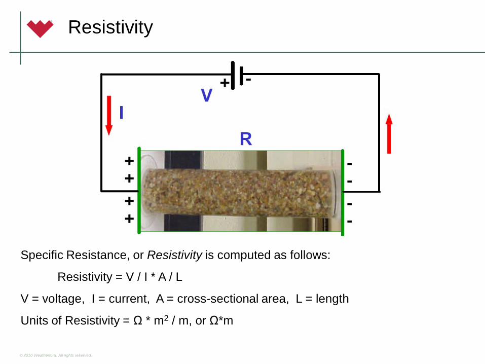
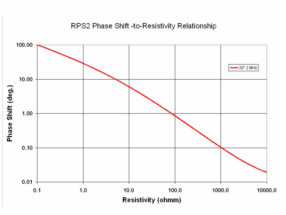
Specific Resistance, or Resistivity is computed as follows:
Resistivity = V / I * A / L
V = voltage, I = current, A = cross-sectional area, L = length
Units of Resistivity = Ω * m2 / m, or Ω*m
Resistivity

Transmitter Antenna (2 MHz to 100 kHz)
Receiver Antennas(6 to 10 inch receiver spacing)
LWD propagation resistivity tools emit radio-frequency electromagnetic waves from a transmitter, and measure the velocity (phase shift) and attenuation (amplitude ratio) between two receiver antennas.
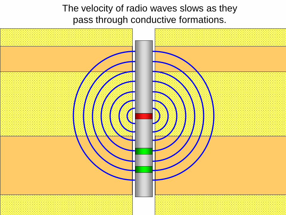
The velocity of radio waves slows as they pass through conductive formations.

The phase shift measurement tells us what fraction of one wave length is represented by the inter-receiver spacing.
Wavelength (λ)
Phase Shift = 130 deg.
phase shift360 = receiver spacing
wave length
Low Resistivity = Slow Velocity = Short Wave Length = Large Phase Shift
T R1 R2

The phase shift measurement tells us what fraction of one wave length is represented by the inter-receiver spacing.
Wavelength (λ)
Phase Shift = 25 deg.
phase shift360 = receiver spacing
wave length
High Resistivity = Fast Velocity = Long Wave Length = Small Phase Shift
T R1 R2
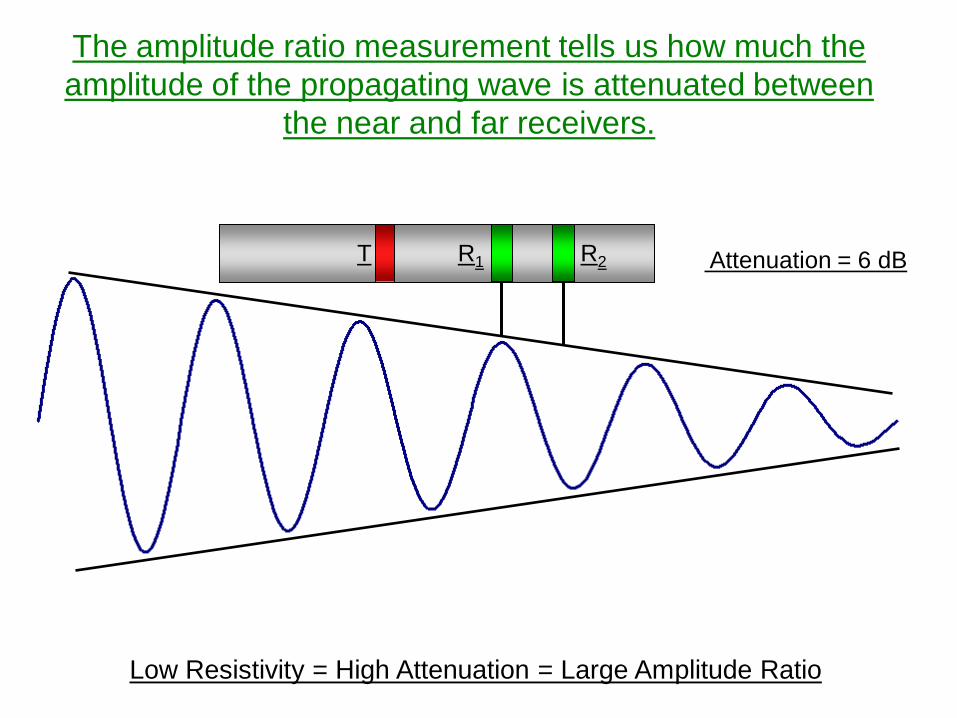
Attenuation = 6 dB
Low Resistivity = High Attenuation = Large Amplitude Ratio
T R1 R2
The amplitude ratio measurement tells us how much the amplitude of the propagating wave is attenuated between
the near and far receivers.
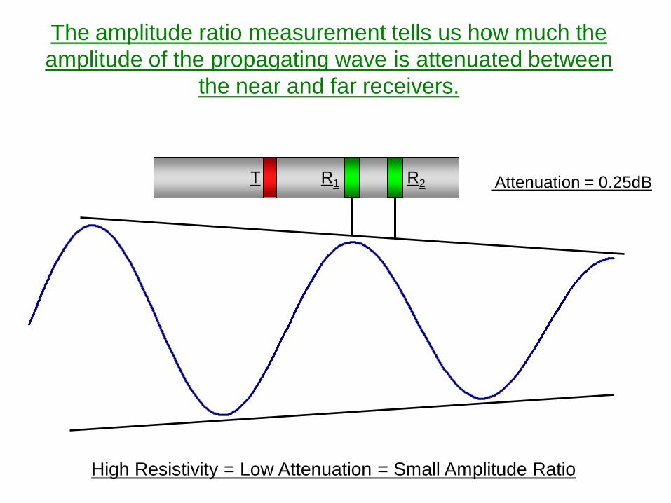
Attenuation = 0.25dB
High Resistivity = Low Attenuation = Small Amplitude Ratio
T R1 R2
The amplitude ratio measurement tells us how much the amplitude of the propagating wave is attenuated between
the near and far receivers.


Phase Shift vs. Attenuation
• Shallower reading• Better vertical resolution• More accurate at high
resistivity
• Deeper reading• Poorer vertical resolution• Less accurate at high
resistivity

© 2010 Weatherford. All rights reserved.
Multi-Frequency Resistivity (MFR)
• Fully Compensated Antenna Design
• 20”, 30”, 46” Antenna Spacings
• Dual Frequency – 2 MHz and 400 kHz
• Phase and Attenuation –• 12 Independent Resistivity Measurements
• 180ºC (356ºF) Temperature Rating
• 30,000 PSI Pressure Rating
• Extensive Modelling and Interpretation Software
© 2010 Weatherford. All rights reserved.
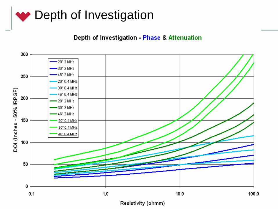
20” 0.4 MHz
30” 0.4 MHz
46” 0.4 MHz
Depth of Investigation

© 2010 Weatherford. All rights reserved.
Oil / Water Contact
© 2010 Weatherford. All rights reserved.
LWD Sensors
• Gamma Ray
– HAGR - High-Temperature Azimuthal Gamma Ray
– SAGR - Spectral Azimuthal Gamma Ray
• Resistivity - MFR – Multi-Frequency Resistivity
• AZD - Azimuthal Density
• TNP – Thermal Neutron Porosity
• ShockWave Sonic
• PressureWave Formation Tester

© 2010 Weatherford. All rights reserved.
Density Measurement
Short Spacing Detector
Long Spacing Detector
Cs137 Gamma ray Source Gamma
rays emitted

© 2010 Weatherford. All rights reserved.
Density Sensor Theory
• The LWD density sensor detectors measure gamma counts through low density windows in a blade on the drill collar
• The “detector blade” is forced against the borehole wall by the rotating action of the drillstring
• The blade will generally not remain in contact 100% of the time creating a condition called “standoff”

© 2010 Weatherford. All rights reserved.
Density Sensor Theory
• If the near and far density values fall on the “spine” (45° line) it indicates that there is no standoff correction needed
• Depending on which side of the spine the point falls will indicate a positive or negative correction
• How severe the correction will be depends on how far from the spine the point falls on a “rib”

© 2010 Weatherford. All rights reserved.
• Compensated Spectral Density with robust spine-and-rib compensation.
• Azimuthal binning for borehole imaging and logging in enlarged holes or w/ bi-center bits.
• Compensated thermal neutron porosity with full environmental corrections
• AZD and TNP sensor have the industry’s highest count rates for faster logging with better statistical precision.
AZD Azimuthal Density and TNP Neutron Porosity
© 2010 Weatherford. All rights reserved.
12
3
4
5
6
78910
11
12
13
14
1516
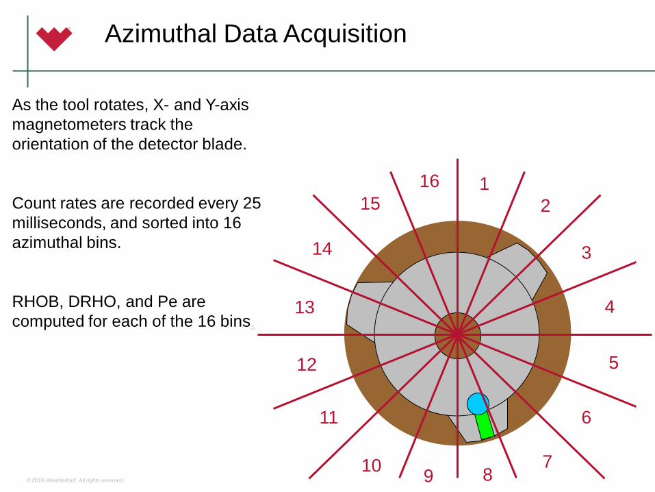
As the tool rotates, X- and Y-axis magnetometers track the orientation of the detector blade.
Count rates are recorded every 25 milliseconds, and sorted into 16 azimuthal bins.
RHOB, DRHO, and Pe are computed for each of the 16 bins.
Azimuthal Data Acquisition
© 2010 Weatherford. All rights reserved.
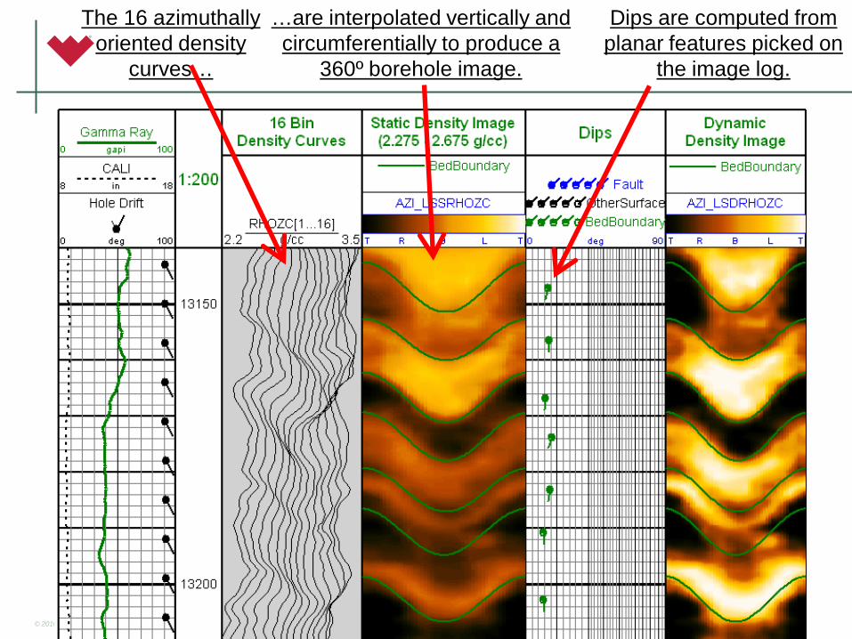
The 16 azimuthally oriented density
curves…
…are interpolated vertically and circumferentially to produce a
360º borehole image.
Dips are computed from planar features picked on
the image log.

© 2010 Weatherford. All rights reserved.
AZD Image with Fault
© 2010 Weatherford. All rights reserved.
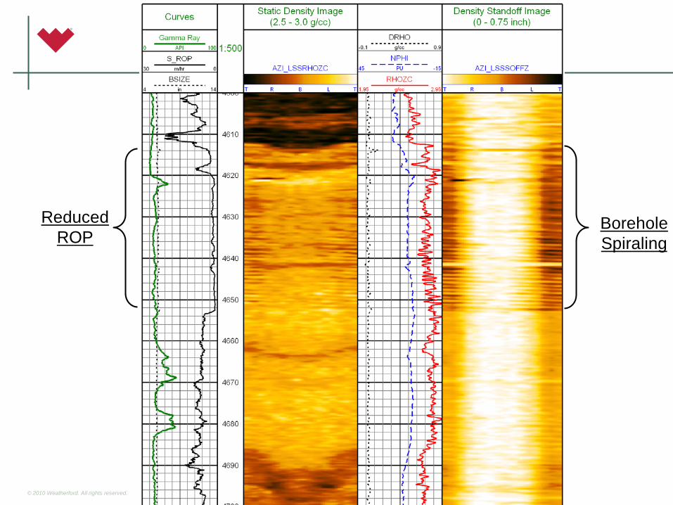
Reduced ROP
Borehole Spiraling
© 2010 Weatherford. All rights reserved.
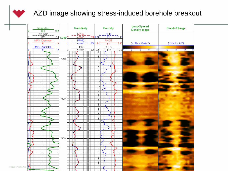
AZD image showing stress-induced borehole breakout

© 2010 Weatherford. All rights reserved.
AZD Summary
• Environment: 165°C (329°F), 30,000 psi
• Tool Sizes: 4-3/4”, 6-3/4”, 8-1/4”
• Output:– RHOB, DRHO, Pe, CALI Curves– Quadrant RHOB, DRHO, PE, Standoff, RHOss– 16-Bin RHOB, DRHO, PE, Standoff, RHOss (Real-Time & Recorded)
• Applications:– Geosteering– Structural Dip Information– Accurate Density in enlarged boreholes– Borehole shape image from standoff
• Spiraling, breakout, packer placement, etc.

© 2010 Weatherford. All rights reserved.
LWD Sensors
• Gamma Ray
– HAGR - High-Temperature Azimuthal Gamma Ray
– SAGR - Spectral Azimuthal Gamma Ray
• Resistivity - MFR – Multi-Frequency Resistivity
• AZD - Azimuthal Density
• TNP – Thermal Neutron Porosity
• ShockWave Sonic
• PressureWave Formation Tester

© 2010 Weatherford. All rights reserved.
Neutron Porosity Measurement
Far Detector
Near Detector
Fast Neutrons released
Neutron Source
Thermal Neutrons return

© 2010 Weatherford. All rights reserved.
Neutron Porosity Measurements
• Source Emits Fast Neutrons ( High Energy)
• Neutrons Travel through the formation and BoreHole
• Hydrogen moderates and slows the neutrons
• Hydrogen depends on Quantity of Oil and Water
• Higher the porosity lesser number of Neutrons reach the Detector
• Ratio of counts on Near and Far Detector gives Thermal Porosity

© 2010 Weatherford. All rights reserved.
Thermal Neutron Porosity Corrections
Five parameters to correct for: borehole size, borehole temperature, mud hydrogen index (HI), borehole and formation salinity
Borehole size: the larger the hole size, the higher the apparent porosity
Borehole temperature: the higher the temperature, the lower the apparent porosity
Mud HI: the higher the mud HI, the Higher the apparent porosity
The borehole and formation salinity: the higher the salinity (Chlorine content) the higher the apparent porosity
53
© 2010 Weatherford. All rights reserved.
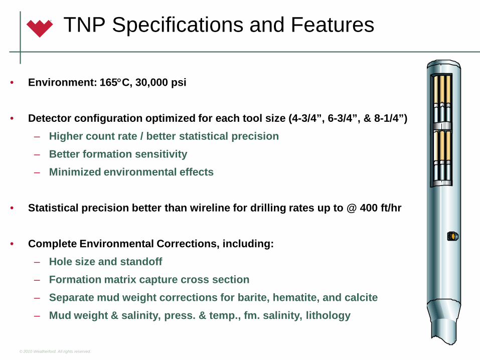
TNP Specifications and Features
• Environment: 165°C, 30,000 psi
• Detector configuration optimized for each tool size (4-3/4”, 6-3/4”, & 8-1/4”)– Higher count rate / better statistical precision– Better formation sensitivity– Minimized environmental effects
• Statistical precision better than wireline for drilling rates up to @ 400 ft/hr
• Complete Environmental Corrections, including:– Hole size and standoff– Formation matrix capture cross section– Separate mud weight corrections for barite, hematite, and calcite– Mud weight & salinity, press. & temp., fm. salinity, lithology

© 2010 Weatherford. All rights reserved.
Gas / Water Contact
© 2010 Weatherford. All rights reserved.
LWD Sensors
• Gamma Ray
– HAGR - High-Temperature Azimuthal Gamma Ray
– SAGR - Spectral Azimuthal Gamma Ray
• Resistivity - MFR – Multi-Frequency Resistivity
• AZD - Azimuthal Density
• TNP – Thermal Neutron Porosity
• ShockWave Sonic
• PressureWave Formation Tester
© 2010 Weatherford. All rights reserved.
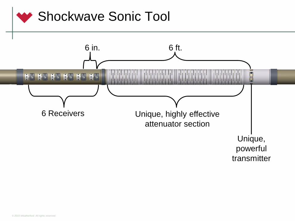
Shockwave Sonic Tool
6 Receivers Unique, highly effective attenuator section
Unique, powerful
transmitter
6 ft.6 in.
© 2010 Weatherford. All rights reserved.
Shockwave Sonic
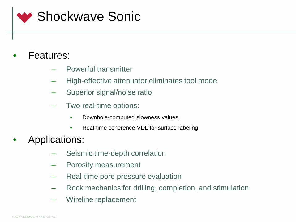
• Features:– Powerful transmitter– High-effective attenuator eliminates tool mode– Superior signal/noise ratio
– Two real-time options:• Downhole-computed slowness values,
• Real-time coherence VDL for surface labeling
• Applications:– Seismic time-depth correlation– Porosity measurement– Real-time pore pressure evaluation– Rock mechanics for drilling, completion, and stimulation– Wireline replacement

© 2010 Weatherford. All rights reserved.
Real-Time Quad-Combo:Δt Picked from Real-Time Coherence VDL
© 2010 Weatherford. All rights reserved.
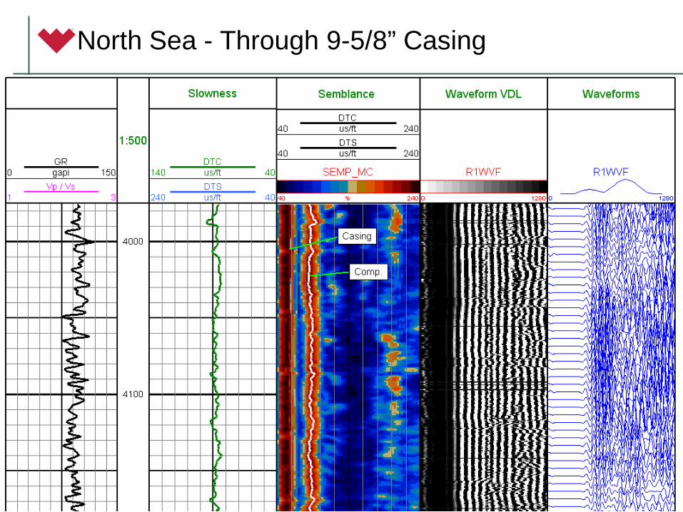
North Sea - Through 9-5/8” Casing

© 2010 Weatherford. All rights reserved.
Casing Shoe, Open Hole, and Salt

© 2010 Weatherford. All rights reserved.
LWD Sensors
• Gamma Ray
– HAGR - High-Temperature Azimuthal Gamma Ray
– SAGR - Spectral Azimuthal Gamma Ray
• Resistivity - MFR – Multi-Frequency Resistivity
• AZD - Azimuthal Density
• TNP – Thermal Neutron Porosity
• ShockWave Sonic
• PressureWave Formation Tester
© 2010 Weatherford. All rights reserved. 63
PressureWave – Formation Pressure Tester
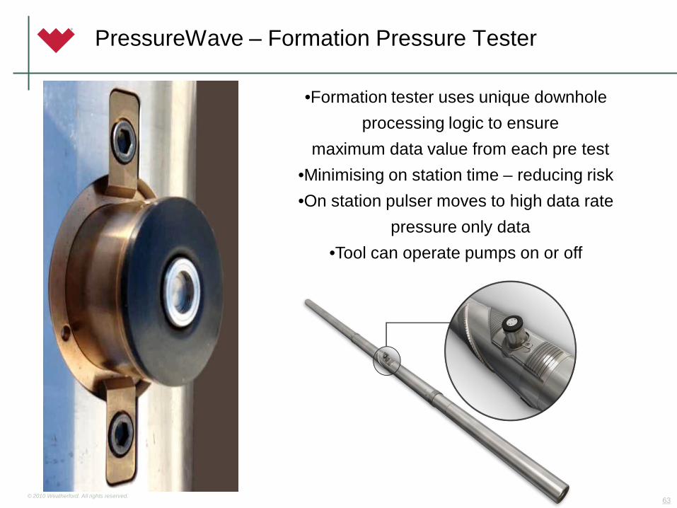
•Formation tester uses unique downhole processing logic to ensure
maximum data value from each pre test •Minimising on station time – reducing risk•On station pulser moves to high data rate
pressure only data •Tool can operate pumps on or off
© 2010 Weatherford. All rights reserved.
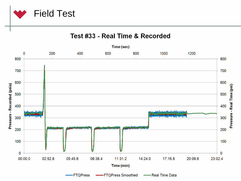
Field Test

© 2010 Weatherford. All rights reserved. 65
Any Questions