introduction to heat exchangers - · pdf fileintroduction to heat exchangers bengt...
TRANSCRIPT

INTRODUCTION TOHEAT EXCHANGERS
Bengt SundénLund Institute of
Technology

What is a Heat Exchanger?
A heat exchanger is a device that is used to transfer thermal energy (enthalpy) between two or more fluids, between a solid surface and a fluid,or between solid particulates and a fluid,at different temperaturesand in thermal contact.
Classification of heat exchangers

Heat exchangers are classified according to
• Transfer process• Number of fluids• Degree of surface contact• Design features• Flow arrangements • Heat transfer mechanisms

Fig. 1 Fluidized-bed heat exchanger.

Fig. 2 Heat transfer surface area density spectrum ofexchanger surfaces ( Shah, 1981).

Fig. 3 (a) Shell-and- tube exchanger with one shell passand one tube pass;
(b) shell-and- tube exchanger with one shell pass and two tube passes.

Fig. 4 Standard shell types and front- andrear-end head types (From TEMA, 1999).

Fig. 5 Gasketed plate-and-frame heat exchanger.

Fig. 6 Plates showing gaskets around the ports (Shah and Focke, 1988).

Fig. 7 Section of a welded plate heat exchanger.

Fig. 8 Bavex welded- plate heat exchanger.

Fig. 9 Spiral plate heat exchanger with both fluids in spiral counter flow.

Fig. 10 (a) Lamella heat exchanger;(b) cross section of a lamella heat exchanger,(c) lamellas
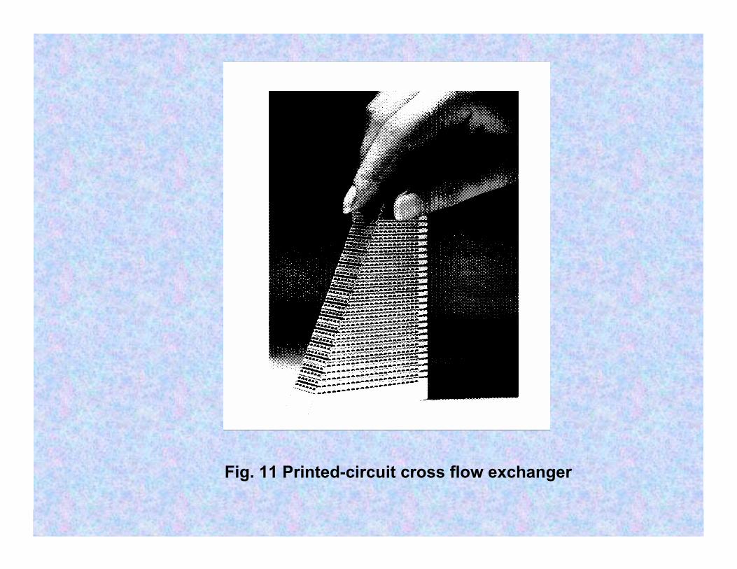
Fig. 11 Printed-circuit cross flow exchanger

Fig. 12 Corrugated fin geometries for plate-fin heat exchangers:(a) plain triangular fin; (b) plain rectangular fin; (c) wavy fin; (d) offset strip fin; (e) multilouver fin; (f) perforated fin.
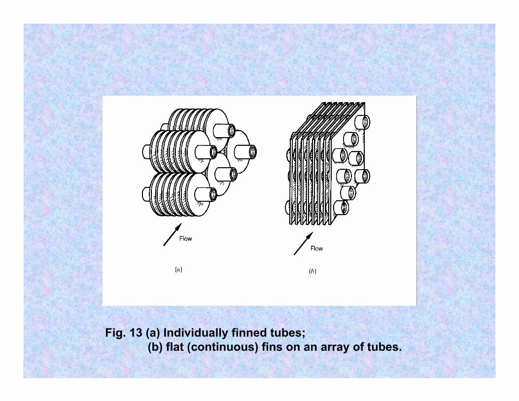
Fig. 13 (a) Individually finned tubes;(b) flat (continuous) fins on an array of tubes.
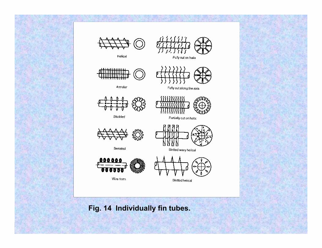
Fig. 14 Individually fin tubes.

Fig. 15 Heat wheel or a rotary regenerator madefrom a polyester film.

Classification according to transfer process
Indirect contact type Direct contact type
Direct transfer Storage Fluidized bed Immiscible fluids
Gas-liquid Liquid-vapour
Single-phase Multiphase

Classification according to number of fluids
Two-fluid Three-fluid N-fluid (N > 3)
Classification according to surface compactness
Gas-to-liquid Liquid-to-liquid and phase-change
Compactβ≥ 700 m2/m3
Non-compactβ < 700 m2/m3
Compactβ ≥ 400 m2/m3
Non-compactβ < 400 m2/m3

Classification according to design or type
Tubular Plate-type Extended surface Regenerative
PHE Spiral Plate coil Printed circuit
Gasketed Welded Brazed
Double-pipe Shell-and-tube Spiral tube Pipe coils
Cross-flow to tubes
Parallel flowto tubes
Plate-fin Tube-fin
Ordinary Separatingwall
Heat-pipewall
Rotary Fixed-matrix Rotatinghoods

Classification according to flow arrangements
Single-pass Multipass
Counter flow Parallel flow Cross flow Split flow Divided flow
Extended surface
Cross-Counter flow
Cross-parallel flow
Compound flow
Shell-and-tube Plate
Parallel counter flowm-shell passesn-tube passes
split-flow Divided-flow
Fluid 1 m passesFluid 2 n passes

Classification according to heat transfer mechanisms
Single-phase convection on both sides
Single-phase convection on one side, Two-phase convection on other side
Two-phase convection on both sides
Combined convection and radiative heat transfer

Classification according to process function
Condensers Liquid-to-vaporphase-changeexchangers
Heaters Coolers Chillers

Convective heat transfer
vägg
Fluid1
Fluid2

Overall heat transfer coefficient
mm1 t
TRtUAQ Δ⋅=Δ⋅=

Expression for overall thermalresistance
oóoFvlw
w
iiFii
1111
oAAA
bAA
TRα
+α
+λ
+α
+α
=

Values of the heat transfer coefficient W/m2K
• Air atmospheric pressure 5-75• Air pressurized 100 - 400• Water, liquid 500-20 000• Organic liquids 50 000• Boiling 2 500 -100 000• Condensation 3 000-100 000
Correlations for the heat transfer coefficient
• Nu = hL/k = function (flow velocity, physicalproperties, geometry) = function (Re, Pr, geometry)

General research needs• How to achieve more compact heat exchangers• High thermal efficiency• Balance between enhanced heat transfer and
accompanied pressure drop• Material issues especially for high temperature
applications• Manufacturing methodology• Fouling• Non-steady operation