introduction to fuel cells - our · pdf fileintroduction to fuel cells scott a barnett,...
TRANSCRIPT

Introduction to Fuel CellsScott A Barnett, Northwestern University
Motivations, applications, history
Fuel cell typesElectrochemical Basics
Electrochemical KineticsCharge Transport
Mass Transport
Stacks and Systems
1

Relevance of Electrochemical Devices: World Energy Flows Sankey Diagram
2

Efficiency Comparisons
• High efficiency means low CO2
• Low emissions of other pollutants• Sulfur removed
• NOx not formed
• No CO
• No particulates• Fuel cells can be sited near point
of use
• Allows direct use of waste heat - effective efficiency > 80%
3

Fuel Cell Introduction
• History• Fuel cell issues• Applications• Overview of fuel cell types
– Phosphoric acid– Proton exchange membrane– Alkaline– Molten carbonate– Solid oxide
4

Historical Origins of Fuel Cells
5

Fuel Cell Milestones
6

Year of First Successful Operation:Energy Conversion Devices
7

Fuel Cell Problems
• Cost– Cost of a new technology is always high initially
• Until high-volume manufacturing brings cost down– Need initial applications without entrenched low-cost
alternatives• Fuels for fuel cells
– Most fuel cells use only pure hydrogen fuel• Not available in large quantities• Difficult to store, transport, transfer, etc.• Usually linked with the “Hydrogen Economy”
– Often chemically convert other fuels to hydrogen• Cost
– Technology is complex– Fuel cells themselves may be only 25% of total system cost
8
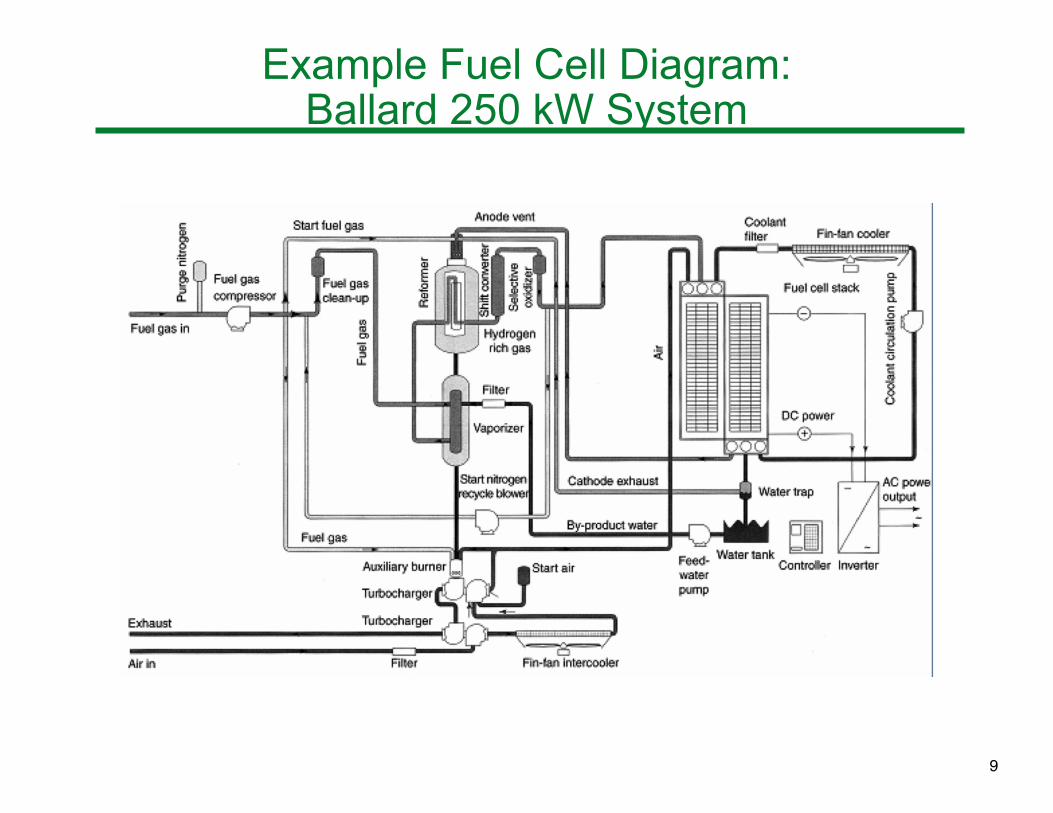
Example Fuel Cell Diagram: Ballard 250 kW System
9

Supplying H2 For Fuel Cells
• Steam or dry reforming (methane)! CH4 + H2O ! CO + 3H2 "H1000K = 206 kJ
• CH4 + CO2 ! 2CO + 2H2 "H1000K = 247 kJ
– Four syngas molecules per CH4
– Endothermic - requires external heat
• Partial oxidation reforming! CH4 + (1/2)O2 ! CO + 2H2 "H1000K = -37 kJ
– Three syngas molecules per CH4
– Exothermic - no external heat needed
– Nitrogen dilution when air is used
• Autothermal - mixed reactions
10

Applications
• Many successful demonstrations completed (according to www.fuelcells.org)– automobiles– bus demonstrations– specialty vehicles– stationary power plants
• Overall, very limited success in penetrating “commercial” markets– Difficult to replace entrenched technologies
• Specialty applications (initial market penetration candidates)– Stable power for telecommunications, banking, etc.– Use “waste” fuels (typically methane) from landfills / wastewater
treatment / breweries– Forklifts without batteries or engine emissions– Portable power in < 1 kW range
• Where electric grid is not available• Emergency backup, military (UAV), remote sensors
11
Electrochemical Basics
• Chemical reaction A + B = AB
– Free energy of formation !GR
– Example reaction (combustion): H2 + (1/2)O2 = H2O• Electrochemical reaction
– Electrolyte membrane separates reactants• Allows passage of ionic but not electronic current
– Current associated with ion transport is balanced by external circuit
• If A is transported as A+ ions through electrolyte, equal numbers of electrons must go through the external circuit
12

Electrochemical Reactions
• Reaction is occurring at the A/electrolyte interface: A = A+z + ze-
– Supplies A+ into the electrolyte and e- into external circuit• Reaction occurring at other side of electrolyte: A+z + ze- = A
– Ions arriving at electrolyte/AB interface combined with electrons from external circuit
• If Bz+ ions rather than Az+ ions are present in the electrolyte, the electron flow direction and the sign of the voltage will be opposite
13

Distinction Between Fuel Cells & Batteries
• In a battery, A and B are usually solid or liquid– A and B can conduct electricity, and thereby can act as
electrodes to supply/remove electrons– Reactants (A & B) contained within device*
• When they are consumed the battery is fully discharged• In a fuel cell, A, B, and AB are generally in the gas (or liquid)
phase– They can be transported into and out of the cell continuously – Electrical connections are made to permanent electrodes
instead of directly to A and B• These are porous to allow ingress of gases/liquids
* An exception is the “flow” battery, where liquid solutions flow continuously into the device
14

Fuel Cells:Combustion Versus Electrochemistry
• Reactants (fuel and oxygen) are separated by an electrolyte, allowing one reactant, and no electrons, to pass
• Conventional method for using fuels - burn them!
• Overall chemical reaction is the same• Reactant is transported as an ion (O2- in example above)• Permanent electrodes on either side of electrolyte
– Provide electrons, since reactants are gaseous or liquid
15

Fuel Cell Types
• Based on electrolyte material: – Polymer electrolyte, phosphoric acid: H+ ions– Solid oxide: O2- ions– Molten carbonate: CO32- ions– Alkaline: OH- ions
Oxygen ion conducting electrolytesHydrogen ion conducting electrolytes
16

Solid Oxide Fuel Cell (SOFC)
• Electrolyte: solid oxide ceramic– Typically yttria-stabilized zirconia
(YSZ)
– Conducts O2- ions• Electrodes: anode usually Ni-YSZ
– Typical cathode: (La,Sr)MnO3
• Operating temperature 600 - 1000oC– High temperature has both
advantages and disadvantages
• Fuel: H2, methane, alcohols, etc.– No CO poisoning issue
• Reactions (assuming H2 fuel)
– Anode: H2 + O2- → H2O + 2e-
– Cathode: (1/2)O2 + 2e- → O2-
• Power density 300 - 1000 mW/cm2
• Typical efficiency 50-60% (90% combined heat and power)
ANODE:
ELECTROLYTE:
CATHODE:(La,Sr)(Mn)O3 (LSM)
LSM-YSZ
Y-doped ZrO2 (YSZ)
Ni-YSZ (active layer)
Ni-YSZ (porous support)
17

SOFC 2
• Advantages:– Fuel flexibility– Non-precious metal catalyst– High-quality waste heat for co-generation– All solid state device– High power density
• Disadvantages:– Significant high-temperature materials issues
• Seals, interconnects, balance of plant– Sealing and interconnecting issues
18

Phosphoric Acid Fuel Cell (PAFC)
• Electrolyte: H3PO4 (pure or highly concentrated)– Contained in a porous SiC matrix
• Keeps electrodes separated, provides mechanical strength, and minimizes reactant gas crossover
– Conducts hydrogen ions– Must be replenished against evaporation
• Electrodes: porous graphite coated with Pt• Operating temperature from 180 - 210oC
– Phosphoric acid solidifies below 42oC– Phosphoric acid phase transformation above 210oC
• Reactions (H2 fuel)
– Anode: H2 → 2H+ + 2e-
– Cathode: (1/2)O2 + 2H+ + 2e- → H2O • Electrical efficiency: 40% (70% combined heat and power)• Power density: 150 - 300 mW/cm2
• Demonstrated as early as 1960’s
19

PAFC 2
• Advantages:– Mature technology– Excellent reliability and long-term performance– Low cost electrolyte
• Disadvantages:– Cost of Pt catalyst– Pt catalyst susceptible to poisoning from reformate fuels
• Can handle ~ 1 % CO• Maximum H2S content of ~ 50 ppm
– Electrolyte is corrosive and must be replenished continuously
– Low power density: 150 - 300 mW/cm2
20

Polymer electrolyte membrane (PEM) fuel cell
• Electrolyte: proton-conducting polymer membrane– Typically perfluorinated sulfonic acid polymer
• Flexible, 20-200 μm thick• Must be maintained in hydrated state
• Electrodes: Pt catalyst on carbon electrode support• Operating temperature <90oC• Reactions (same as PAFC)
– Anode: H2 → 2H+ + 2e-
– Cathode: (1/2)O2 + 2H+ + 2e- → H2O • Fuels: typically H2, but can also use methanol, formic acid
– e.g. direct-methanol fuel cell (DMFC)– Pt catalyst readily poisoned by CO and S
• Even worse than PAFC because of lower temperature• Power density: 300 - 1000 mW/cm2
• Electrical efficiency: 40 - 50%
21

PEMFC 2
• Advantages:– High power density– Good start-stop capability– Suitable for portable applications due to low temperature
• Disadvantages:– Cost of Pt catalyst– Expensive polymer membrane and ancillary components– Active water management often required– Very poor CO and S tolerance
22

Alkaline Fuel Cell (AFC)
• Electrolyte: aqueous KOH– Conducts OH- ions
• Electrodes: porous graphite coated with Pt, or Ni• Operating temperature from 60 - 250oC• Fuel: pure H2 (typically uses pure O2 oxidant)
– Cannot tolerate CO2 in fuel/oxidant • Reaction 2OH- + CO2 → CO32- + H2O depletes OH- • Can form solid K2CO3
• Reactions– Anode: H2 + 2OH- → 2H2O + 2e-
– Cathode: (1/2)O2 + H2O + 2e- → 2OH- • Water consumed at cathode, produced at anode• Oxygen reduction reaction (ORR) much faster in alkaline
medium compared to acidic medium• Power density: 150 - 400 mW/cm2
• Electrical efficiency: 50%• Successful use in spacecraft from 1960’s
23

AFC 2
• Advantages:– Excellent cathode performance – Can use non-precious metal catalyst such as Ni– Low materials and electrolyte cost
• Disadvantages:– Must use pure H2 and O2 (no CO2)
• Difficult for terrestrial applications– KOH electrolyte may need periodic replacement– Must remove water from anode
24

Molten Carbonate Fuel Cell (MCFC)
• Electrolyte: molten mixture of alkali carbonates– Li2CO3 and K2CO3 immobilized in LiOAlO2 porous matrix– Conducts CO32- ions
• Electrodes: anode usually Ni-Cr alloy; Cathode: NiO:Li• Operating temperature ~ 650oC• Fuel: H2, methane, simple alcohols
– No CO poisoning issue• Reactions (assuming H2 fuel)
– Anode: H2 + CO32- → CO2 + H2O + 2e-
– Cathode: (1/2)O2 + CO2 + 2e- → CO32-
• CO2 consumed at cathode, produced at anode– System must re-circulate CO2 (mix exhaust with inlet air)
• Power density ~ 100 - 300 mW/cm2
• Typical efficiency 45 - 55% (90% combined heat and power)• Used continuously (stationary power) to avoid freeze/thaw
25
MCFC 2
• Advantages:– Fuel flexibility– Non-precious metal catalyst– High-quality waste heat for co-generation
• Disadvantages:– CO2 recycling required– Corrosive, molten electrolyte– Degradation/lifetime issues– Relatively expensive materials
26
Electrochemical Thermodynamics
• Thermodynamics provides a foundation for understanding electrochemical devices– Relation between thermo and electrical quantities
• Topics– Nernst potential– Effects of T, P, and composition– Efficiency
27

Equilibrium Potential 1
• The cell (system) consists of three sub-systems, electrodes (1 and 2) separated by an electrolyte membrane (3)
• Equilibrium condition can be written in variational form in terms of Gibbs free energy:
"G # 0– This states that all possible variations in the system yield
constant or increasing G• Equivalent to the condition that G is at a minimum
• Total "G is sum of individual parts: "G = "G1 + "G2 + "G3, where "G1 = -S1"T + V1"P + $#µi
1"ni1 + %1"q1
"G2 = -S2"T + V2"P + $#µi2"ni
2 + %2"q2
"G3 = -S3"T + V3"P + $#µi3"ni
3 + %3"q3
• Free energy includes additional work terms:– Chemical work of adding (or removing) "ni moles of species i
at chemical potential µi: µi"ni
– Electrical work of adding (or removing) "q moles of charge at electrical potential %: %"q
28

Equilibrium Potential 2
• Consider cell at fixed T and P• At steady state there is no net change in the composition or
charge state in the electrolyte, so "ni3 = 0 and "q3 = 0
• The equilibrium condition can now be written: "G = 0 = $#µi
1"ni1 + $#µi
2"ni2 + %1"q1 + %2"q2
– Using just the equality portion of the condition• The "ni and "q terms are not independent, but are related as
given by the chemical reaction taking place in the cell– In general, a chemical reaction can be written as:
• For example, express H2 + (1/2)O2 = H2O in the form:
H2O - H2 - (1/2)O2 = 0
– In this example, &H2 = -1, &O2 = -1/2, &H2O = 1
• If the system undergoes a transformation where n1 varies by "n1, n2 varies by "n2, etc., the increments are related by:
"n1/&1 = "n2/&2 = …. = "nr/&r = "nelec/z = "'– Where ' is the progress variable
! iAi = 0i=1
r
"
29

Equilibrium Potential 3
• The "nelec/z term is included for an electrochemical reaction
– Relates the change in number of moles of electronic charge "nelec to "'
– z = number of electrons in the reaction as written• Thus, "nelec = z"'• This can be converted to charge q in coulombs using: "q = (eNAv) "nelec = Fz"'
– Where e = coulombs/electron; NAv = Avogadro’s number
– F = eNAv = Faraday’s constant
• The charge flows between sub-systems 1 and 2, such that "q1 = -"q2 = zF"'• Substituting into the equilibrium condition yields: 0 = $#µi
1"ni1 + $#µi
2"ni2 + zF"' (%1 - %2)
30

Equilibrium Potential 4
• As the reaction proceeds, the "ni values are given by the
progress variable ("ni = &i "')
• Re-writing the chemical potential sum in terms of the progress variable:
( 0 = $# µi1 &i"' + $# µi2 &i"' + zF"' (%1 - %2)
– It’s well known which side of the cell (electrode 1 or 2) each species is on: normally drop the superscripts on μ terms
• Combine sums: 0 = $# µi&i"' + zF"' (%1 - %2)
– Be sure to evaluate each µi on the side where i appears
– Or: zF(%1 - %2) = )$# µi&i
• Note the general definition of reaction free energy:
– E is the so-called Nernst potential
!GR " # iµii=1
r
$%&'()*
E ! "# = (#1 $# 2 ) = $"GR
zF
31

Cell Potential: Effect of Gas Composition
• In a case where the reactants and products are pure species in their standard states, !GR = !G0
R, such that
• In most cases, however, one needs to determine !GR in terms of tabulated !G0
R values for reactions– E.g. in a fuel cell with gas phase species at some selected
partial pressures• Relate chemical potentials to activities (& gas phase pressures):
µi = µi0 (T) + RT ln ai
– R = gas constant • Define standard reaction free energy:
• Thus:
• Dividing by -1/zF yields:
!GR0 " # iµi
0
i=1
r
$%&'()*
!GR " !GR0 = # i (µi " µi
0
i=1
r
$ ) = RT lnai#i
i=1
r
$ = RT ln ai#i
i=1
r
%
E0 = !"GR0 / zF
E = E0 !RTzFln ai
"i
i=1
r
# = E0 !RTzFlnK K = ai
!i
i=1
r
"32
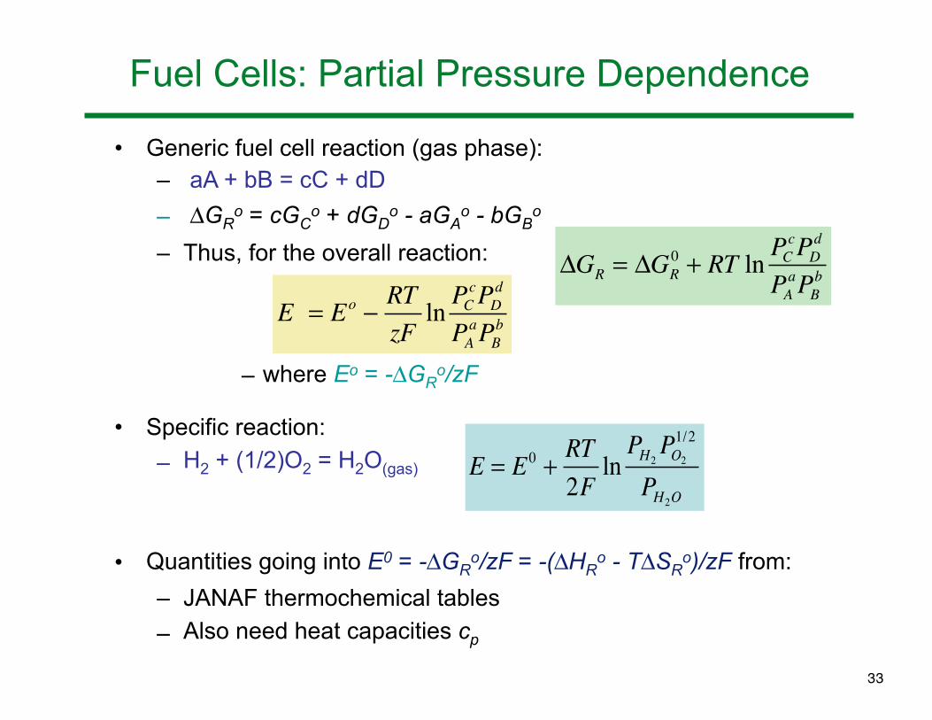
Fuel Cells: Partial Pressure Dependence
• Generic fuel cell reaction (gas phase):– aA + bB = cC + dD
– !GRo = cGC
o + dGDo - aGA
o - bGBo
– Thus, for the overall reaction:
– where Eo = -!GRo/zF
• Specific reaction:
– H2 + (1/2)O2 = H2O(gas)
• Quantities going into E0 = -!GRo/zF = -(!HR
o - T!SRo)/zF from:
– JANAF thermochemical tables
– Also need heat capacities cp
!GR = !GR0 + RT ln PC
cPDd
PAaPB
b
E = Eo !RTzFln PC
cPDd
PAaPB
b
E = E0 +RT2F
lnPH2PO2
1/2
PH2O
33
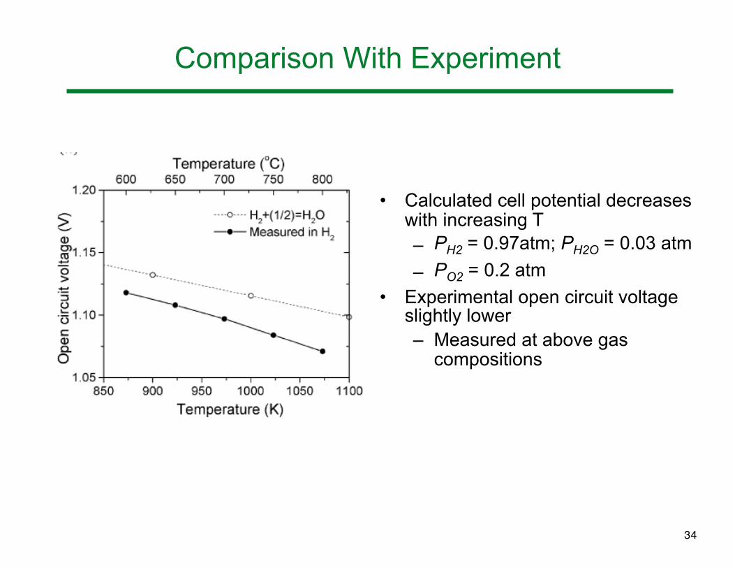
Comparison With Experiment
• Calculated cell potential decreases with increasing T– PH2 = 0.97atm; PH2O = 0.03 atm
– PO2 = 0.2 atm
• Experimental open circuit voltage slightly lower– Measured at above gas
compositions
34
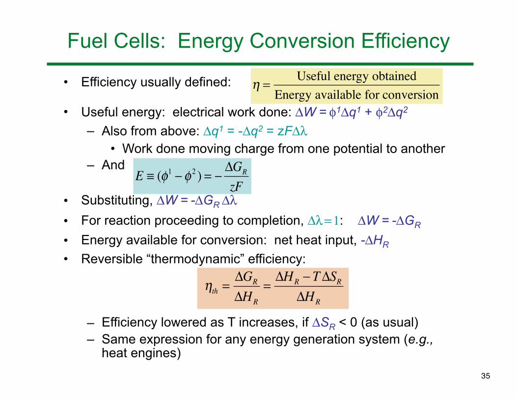
Fuel Cells: Energy Conversion Efficiency
• Efficiency usually defined:
• Useful energy: electrical work done: !W = %1!q1 + %2!q2
– Also from above: !q1 = -!q2 = zF!' • Work done moving charge from one potential to another
– And
• Substituting, !W = -!GR !'• For reaction proceeding to completion, !' = 1: !W = -!GR
• Energy available for conversion: net heat input, -!HR
• Reversible “thermodynamic” efficiency:
– Efficiency lowered as T increases, if !SR < 0 (as usual)– Same expression for any energy generation system (e.g.,
heat engines)
! =Useful energy obtained
Energy available for conversion
E ! ("1 #" 2 ) = #$GR
zF
!th ="GR
"HR
="HR # T"SR
"HR
35
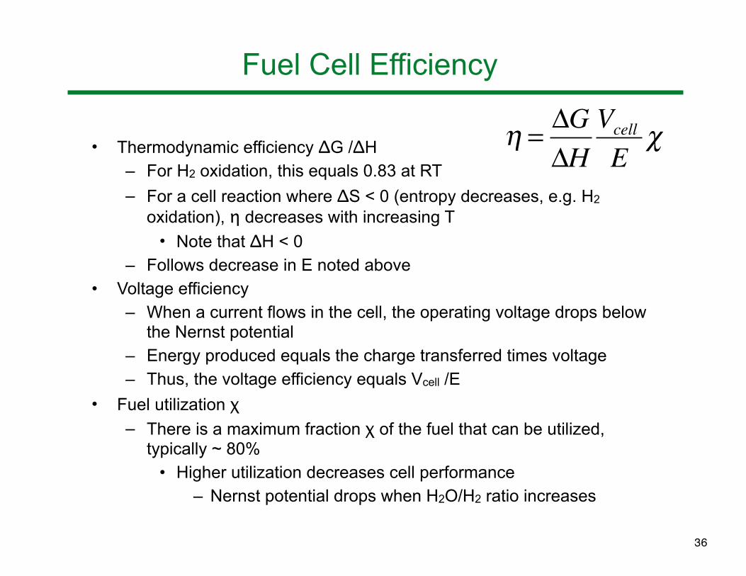
Fuel Cell Efficiency
• Thermodynamic efficiency ΔG /ΔH– For H2 oxidation, this equals 0.83 at RT
– For a cell reaction where ΔS < 0 (entropy decreases, e.g. H2 oxidation), η decreases with increasing T
• Note that ΔH < 0– Follows decrease in E noted above
• Voltage efficiency– When a current flows in the cell, the operating voltage drops below
the Nernst potential– Energy produced equals the charge transferred times voltage– Thus, the voltage efficiency equals Vcell /E
• Fuel utilization χ– There is a maximum fraction χ of the fuel that can be utilized,
typically ~ 80%• Higher utilization decreases cell performance
– Nernst potential drops when H2O/H2 ratio increases
! = "G"H
Vcell
E#
36

Efficiency Illustration
• Example: SOFC• Red curve: Nernst potential versus fuel utilization
– Nernst voltage as low as 0.8V for depleted fuel• Black curve: overall efficiency
– Includes both fuel utilization and voltage efficiency
37
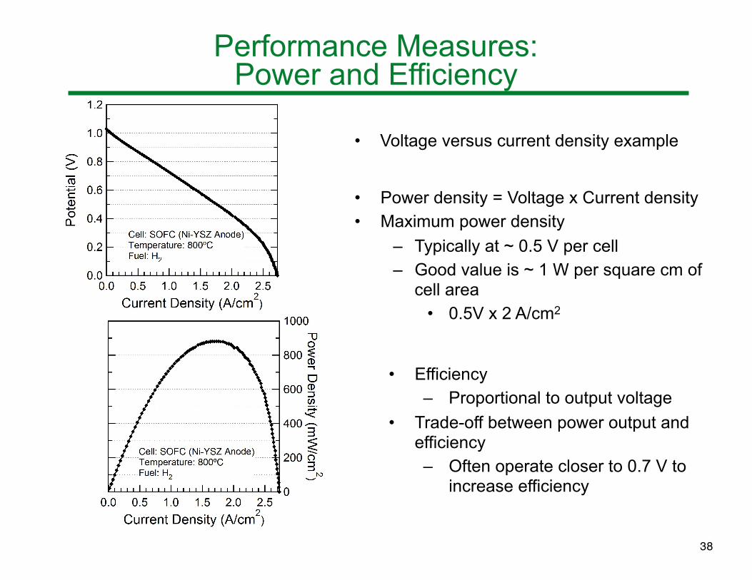
Performance Measures:Power and Efficiency
• Voltage versus current density example
• Power density = Voltage x Current density• Maximum power density
– Typically at ~ 0.5 V per cell– Good value is ~ 1 W per square cm of
cell area• 0.5V x 2 A/cm2
• Efficiency– Proportional to output voltage
• Trade-off between power output and efficiency– Often operate closer to 0.7 V to
increase efficiency
38
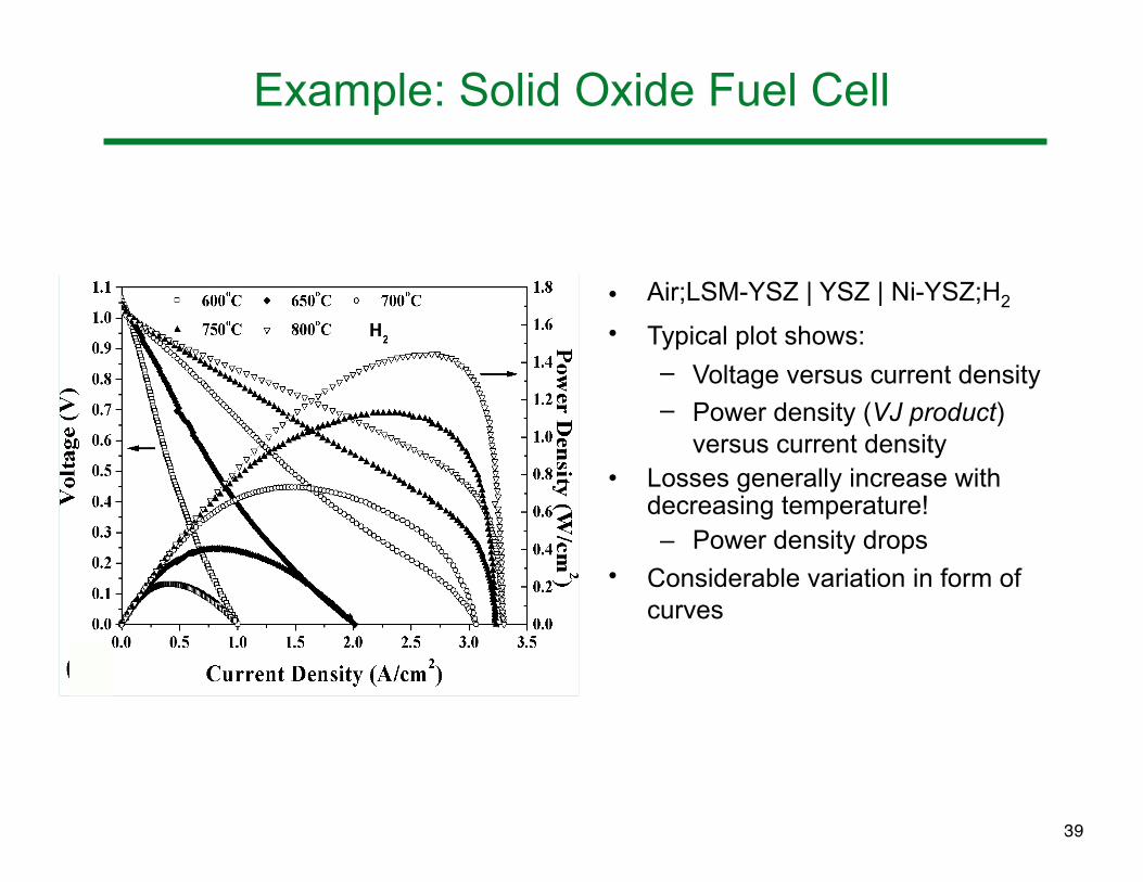
Example: Solid Oxide Fuel Cell
• Air;LSM-YSZ | YSZ | Ni-YSZ;H2
• Typical plot shows:
– Voltage versus current density– Power density (VJ product)
versus current density• Losses generally increase with
decreasing temperature!– Power density drops
• Considerable variation in form of curves
39

Loss Mechanism Discussion
• Kinetic considerations provide a basis for understanding current-voltage response– Goal: predict electrochemical device performance under a
range of loading conditions• The section below gives detailed descriptions of:
– Activation polarization associated with charge transfer• Butler-Volmer and Tafel equations
– Activation polarization limited by adsorption• The following sections discuss:
– Ohmic polarization– Mass transport (concentration) polarization
40

Introduction: Electrochemical Cell Losses
Various losses related to matter/charge transport reduce the cell voltage V:
• E = Nernst potential
• $Ohm = Ohmic resistance
– Often dominated by electrolyte• $A = anode polarization
• $C = cathode polarization• Each of the electrodes can have two main
categories of polarization: – Activation (low current)– Mass transport (high current)
• $x = decrease in cell potential due to crossover currents
V = E !"Ohm !"actC !"act
A !"massC !"mass
A !"x
41

Charge Transfer 1
• For a generic reaction (R * P), transition state theory gives molar flux of product formation J = dCP
*/dt = kCR*; k depends on:
– Probability of “activated complexes” at energy maximum– Rate at which they cross the barrier towards products
• !G0ǂ = energy difference between reactant and activated states (!H0ǂ & !S0ǂ, associated enthalpy and entropy)
• R = gas constant; T = temperature (K); h = Planck const
– CR* , CP
* = concentration of reactant/product species at surface
– Reaction rate J1 (“1” denotes forward direction) given by:
J1 = CR* f1 exp(-!G1
ǂ/RT)
– kBT/h = decay rate from activated to product state - often replaced by a frequency factor f
k =kBThexp !"G0±
RT#$%
&'(=kBThexp "S0±
R#$%
&'(exp !"H 0±
RT#$%
&'(
42

Charge Transfer 2
• Net rate J includes forward and reverse reactions: J = J1 - J2
– Using an expression for J2 similar to that for J1
J = CR* f1 exp(-!G1
ǂ/RT) - CP* f2 exp(-!G2
ǂ/RT)
• CP* = product surface concentration
• !G2ǂ = energy barrier between product and activated
states• The above can be written in terms of the forward activation
barrier and the Gibbs potential change for the reaction !GR
– Use !GR = !G1ǂ - !G2
ǂ
J = CR* f1 exp(-!G1
ǂ/RT) - CP* f2 exp[(-!G1
ǂ + !GR)/RT]
• Relate above flux terms (J’s) to current densities j using j=zFJ– For example, the forward current j1 = zFCR
* f1 exp(-!G1ǂ/RT)
– Reverse current: j2 = zFCP* f2 exp[(-!G1
ǂ + !GR)/RT]
• At equilibrium, forward and reverse currents are equal: j0 = j1 = j2
– Termed the “exchange” current density– No net current - dynamic equilibrium
43
Charge Transfer 3
• A way of viewing the electrochemical process at equilibrium:– Offsetting effects of chemical reaction energy and electric
potential energy (!GR = -zF!%)
• !GR = Gibbs potential of specific electrode reaction
• !%int = electric potential energy across interface– Only part of overall potential across cell
» “Galvani potential”• Reaction wants to proceed forward• Electrical potential retards and exactly balances this
• Externally applied voltage or a reduction of the cell potential E (e.g. by loading) cause deviations from this equilibrium – Portion of this “overpotential” at electrolyte/electrode
interfaces called “activation overpotential” +act – Electric potential directly impacts e- energy vs rxn coordinate– Changes reaction rates: changes the size of the activation
barriers differently in the forward and reverse directions– Occurs at both electrodes - must provide equal currents
44
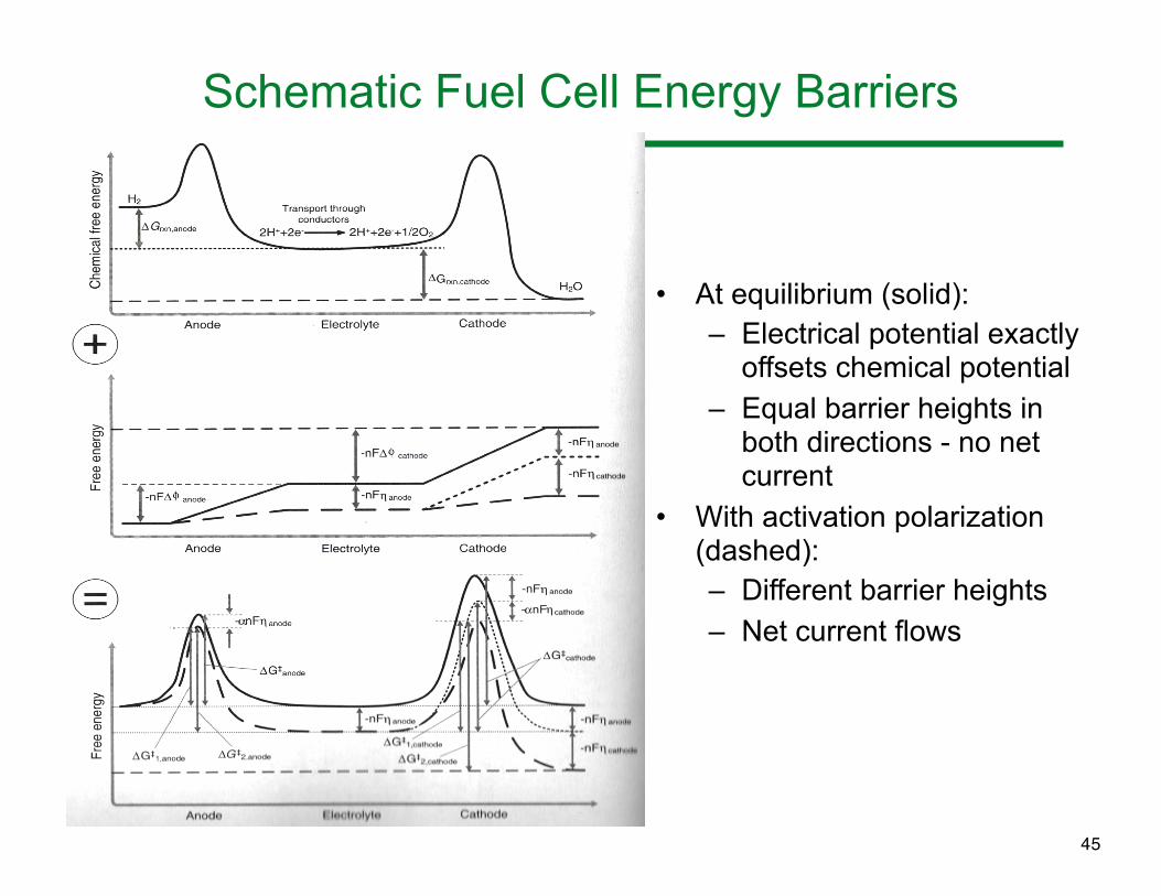
Schematic Fuel Cell Energy Barriers
• At equilibrium (solid):– Electrical potential exactly
offsets chemical potential– Equal barrier heights in
both directions - no net current
• With activation polarization (dashed):– Different barrier heights– Net current flows
45

Charge Transfer 4
• Change in activation barriers due to applied potential
– Forward barrier: ,zF+act
– Reverse barrier: (1-,)zF+act
• , = transfer coefficient - depends on symmetry of barrier
– Symmetric barrier, , = 0.5, often assumed
• Effect of +act on current density
– Recall that at equilibrium (no added potential +act = 0)
j = 0 = zFCR* f1 exp(-!G1
ǂ/RT) - zFCP* f2 exp[(-!G1
ǂ - !GR)/RT]
• Where each of the two terms, j1 and j2, respectively, are equal: j0 = j1 = j2
– With non-zero +act, the first term becomes
zFCR* f1 exp[(-!G1
ǂ+,zF+act)/RT] = j0 exp(,zF+act/RT)
– And similarly for the second term, such that j = j0 [exp(,zF+act/RT) - exp-({1-,}zF+act/RT)]
46

Charge Transfer 5
• Assumes that CR* and CP
* are unaffected by +act
• A better expression that accounts for this:
– j00 = exchange current density measured for concentrations present at zero current
– Butler-Volmer equation
• Exponential dependence of j on +act • Drawing current from a cell requires that the voltage be
reduced from the equilibrium value E• Can be approximated as linear for small j• Generally applicable to single-electron transfer events• Very good approximation for single-step electrochemical
reactions– Or for multi-step reactions where electron transfer
step is rate limiting
j = j00 CR
*
CR0 e
! zF"act /RT #CP*
CP0 e
#(1#! )zF"act /RT$%&
'()
47

Exchange Current Density
• A good fuel cell or battery should achieve large j at a low +act in order to produce power with relatively little voltage loss
• In the Butler-Volmer equation, the pre-factor j0 is a key term determining j
– Recall the equation for j0: j0 = zFCR* f1 exp(-!G1
ǂ/RT)• (Written for the forward reaction)
• A higher j0 value can be achieved by:
– Increasing the reactant concentration CR*
• e.g., by pressurizing the device
– Decreasing the activation barrier !G1ǂ
• Introduce electrode surfaces with “catalytic” properties, i.e. that have a lower barrier height
– Increasing the temperature T– Increasing number of possible reaction sites per unit area
• By increasing the interface roughness• Electrode microstructure is important
48

Butler-Volmer: Simplified Forms
– +act is very small (j << j0), typically < 15 mV at ambient T
• Use the simplified form of B-V equation where the concentrations don’t vary with current
j = j0 [exp(,zF+act/RT) - exp-({1-,}zF+act/RT)]
yields j = j0 zF+act/RT• Linear relation between overvoltage and current
• Polarization resistance: RP,act = +act /j = RT/ j0 zF
– +act is large (j > j0), typically > 50-100 mV at ambient T
• Forward reaction term dominates: j = j0 exp(,zF+act/RT) or, solving for +act
+act = -(RT/,zF) ln j0 + (RT/,zF) ln j
• “Tafel equation” form: +act = a + b ln j
– b = RT/,nF = Tafel slope
– a = -(RT/,nF)lnj0 -- measurement yields j0 value49

Example: Tafel Behavior
• For PEM cathodes, 80oC, H2/O2 with different Pt loadings• Accurate measurement of potential across cathode requires that
ohmic losses and anode losses be removed• LEFT: Increasing Pt increases density of reaction sites,
increases a, exchange current density • RIGHT: replot as current normalized to Pt loading
– Exchange current density per unit area of Pt is constant
50

Electrode Microstructure: PEMFC
• Use high surface area carbon powder decorated with nano-scale (2-3 nm) Pt particles– Achieves high three-phase
boundary density with minimum amount of Pt
– Also introduces stability issues due to Pt coarsening
– Image: TEM micrograph of Pt/C• Percolating electronic pathway from
gas diffusion layer to C to Pt• Percolating ionic pathway through
Nafion phases• Percolating pore pathways to allow
reactant/product access
20 nm
51
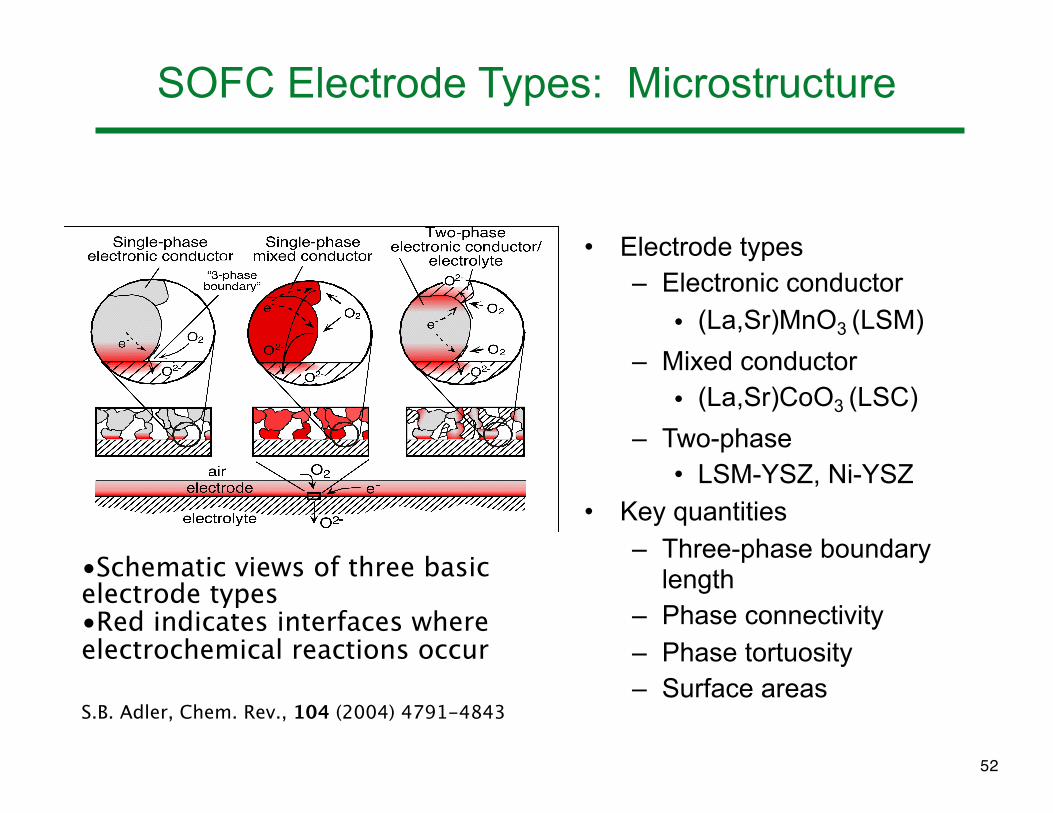
SOFC Electrode Types: Microstructure
• Electrode types– Electronic conductor
• (La,Sr)MnO3 (LSM)
– Mixed conductor
• (La,Sr)CoO3 (LSC)
– Two-phase• LSM-YSZ, Ni-YSZ
• Key quantities– Three-phase boundary
length– Phase connectivity– Phase tortuosity– Surface areas
•Schematic views of three basic electrode types•Red indicates interfaces where electrochemical reactions occur
S.B. Adler, Chem. Rev., 104 (2004) 4791-4843
52

SOFC Composite Electrodes
Important Features:
• Three Phase Boundaries (TPBs)
• Phase Connectivity*
• Phase Tortuosity*
* Not available from 2D imaging and stereology
Ano
deC
atho
de
2O2-
4e-
O2 from air
2O2-
4e-
2H2 2H2O!"#$%&'())*"+$%,-'.%/"01(23
!"4)3'56$%&'())*"+$%,-'.%/"01(23
!"0$63"01(23
53

FIB-SEM Tomography
10 µm
54
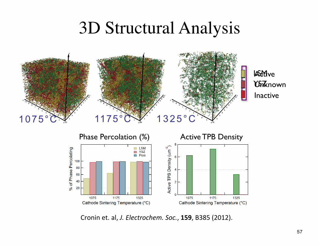
3D Structural Analysis
1075°C 1175°C 1 3 2 5 ° C
Phase Percolation (%) Active TPB Density
ActiveUnknownInactive
LSMYSZ
+6$%&%"357"()8"!"#$%&'()*'+&,"#-*'"8"!"#8"9:;<"=>?@>A7
57
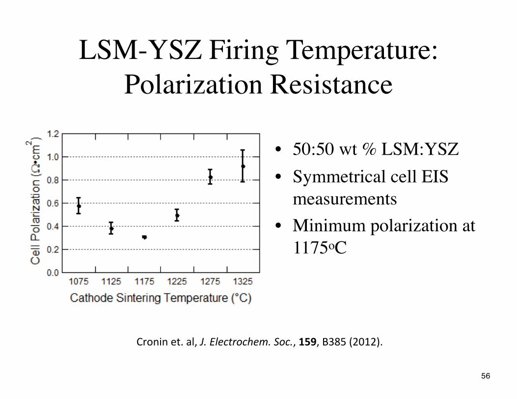
LSM-YSZ Firing Temperature:Polarization Resistance
• 50:50 wt % LSM:YSZ• Symmetrical cell EIS
measurements• Minimum polarization at
1175oC
+6$%&%"357"()8"!"#$%&'()*'+&,"#-*'"8"!"#8"9:;<"=>?@>A7
56
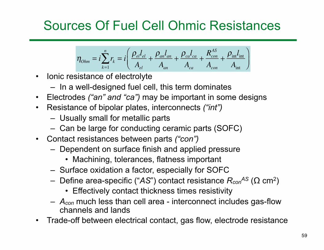
Sources Of Fuel Cell Ohmic Resistances
• Ionic resistance of electrolyte – In a well-designed fuel cell, this term dominates
• Electrodes (“an” and “ca”) may be important in some designs• Resistance of bipolar plates, interconnects (“int”)
– Usually small for metallic parts– Can be large for conducting ceramic parts (SOFC)
• Contact resistances between parts (“con”)– Dependent on surface finish and applied pressure
• Machining, tolerances, flatness important– Surface oxidation a factor, especially for SOFC– Define area-specific (“AS”) contact resistance RconAS (Ω cm2)
• Effectively contact thickness times resistivity– Acon much less than cell area - interconnect includes gas-flow
channels and lands• Trade-off between electrical contact, gas flow, electrode resistance
!Ohm = i rkk=1
n
" = i #ellelAel
+#anlanAan
+#calcaAca
+RconAS
Acon+#intlintAint
$%&
'()
59

Anode-Supported SOFC
• Ni-YSZ support• Ni-YSZ electrochemically active
layer with fine microstructure• Thin YSZ electrolyte• LSM-YSZ active layer• Image: 33 cm x 33 cm cell
– Ni-YSZ support by tape casting
– Screen print YSZ and co-fire – Print and fire LSM layers
• LSM current collector
33 x 33 cm2 – Long Term Testing
1.2
1200A power curve
1 0
1.2
0.8
1
0.8
1.0
0.6
Cell V
olt
ag
e (
V)
0.6
Vo
lta
ge
, V
0 2
0.4
Degradation rate = 11.5 mV / 1000 hours
0 2
0.4
1 Cell Stack - 961 cm2 Active Area
Furnace Temperature: 750°C
Fuel: 55 H2:45 N2 + 3% H2O, Uf = 50%
0
0.2
0:00:00 240:00:00 480:00:00 720:00:00 960:00:00 1200:00:00 1440:00:00 1680:00:00 1920:00:00 2160:00:00
0.0
0.2 Fuel: 55 H2:45 N2 3% H2O, Uf 50%
Oxidant: Air, Ua = 25%
Current: 500 A (0.5 A/cm2)
Time (hours)
Typical SOFC Microstructure
(La,Sr)(Mn)O3 (LSM)
LSM-YSZ
Y-doped ZrO2 (YSZ)
Ni-YSZ (active layer)
Ni-YSZ
(porous support)
ANODE:
ELECTROLYTE:
CATHODE:
Microstructure details often not known or ignored! 73

Stacking
• Note mechanical compression used in gas sealing
1 kW Stack Module
• Ferritic stainless steel sheet
metal interconnect
• Cross-flow gas delivery
with manifolds integrated
i t th i t tinto the interconnect
• Compressible ceramic
gasket seals
• Cell Active Area = 121 cm2• Cell Active Area = 121 cm2
• Number of Cells = 28
• Successfully implemented in
a 4 x 1 kW configuration witha 4 x 1 kW configuration, with
multiple long term tests
74

Conclusions
• Fuel cells carry out chemical to electricity conversion with high efficiency and low pollutant emission
• Wide range of applications• Five major classes based on type of electrolyte• Theoretical cell potential and efficiency depend on
thermodynamics of reaction and operating conditions– Predicted Nernst potential
• Various kinetic terms limit cell current (and power) density– Electrochemical charge transfer rate
• Butler-Volmer and Tafel equation– Surface adsorption– Electrical resistance– Mass transport: gas flow and diffusion
• Numerous challenges in manufacturing, sealing, interconnecting, stacking, and system design
75