introduction to fpga - iit kanpurstudents.iitk.ac.in/eclub/assets/lectures/summer14/fpga_avi.pdf ·...
TRANSCRIPT

Introduction to FPGAAVI SINGH

Prerequisites Digital Circuit Design - Logic Gates, FlipFlops, Counters, Mux-Demux
Familiarity with a procedural programming language like C

Bottom Up Design

Logic Gates

Circuits using Logic Gates

A little more Complication

Flip Flops

Counters

Microprocessors Made up of several smaller blocks, as discussed previously.
Can contain hundreds of millions of gates.
For Example: Intel i7 ~ 731m gates!
Our Dilemma For better performing computer, we need processors with a large number of gates.
But, how do we design with so many gates?
Do we ‘draw’ these circuits? Too tedious!

HDLs to the Rescue Hardware Description Languages (HDLs)
Allow you to ‘write’ down hardware.
How? We will see.
Some of the popular HDLs: Verilog (mainly in the US), VHDL

Example: A Tri-State Buffer
module tri_buf (a,b,enable); input a; output b;input enable; wire b; assign b = (enable) ? a : 1'bz; endmodule

How HDLs help you get the circuit

Where do FPGAs come in the picture? FPGA stands for Field Programmable Gate Arrays
You can think of it as drawing board made out of silicon: you can implement any digital circuit on it.
An HDL code after synthesis can be uploaded to the FPGA, and we can test our design in the real world, before going to production with it.

How does it beat a microcontroller?Parallel processing.
Digital Circuits are way faster than algorithms running on a CPU.
User configurable input/output pins: You can have dozens of external interrupts (or internal interrupts), have as many UART or SPI ports as you want.
You can implement a processor on an FPGA, add external memory and few other peripherals, and you have a brand new micro-controller of your own, which can even run software.

Reconfigurable Logic Blocks

Coding in Verilog Consists of various building blocks called Modules
Communication between a module and its environment is achieved by using Ports
Ports are of three types: input, output, inout

Module A “Black Box” in Verilog with inputs, outputs and internal logic working.
So, a module can be used to implement a counter.
A module is defined as module <specific type>(<port list>);
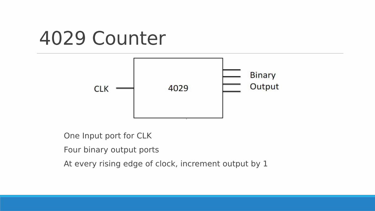
4029 Counter
One Input port for CLK
Four binary output ports
At every rising edge of clock, increment output by 1

Declaring Module Way 1:
module 4029(clk, a, b, c, d, reset, enable);
//Assuming two more input pins, reset and
//enable with their corresponding functioning
Way 2:
module 4029(clk, out, reset, enable);
What is the difference in the two?

Declaring Ports Way 1:
input clk;
input reset;
input enable;
output a,b,c,d;
Way 2:
input clk;
input reset;
input enable;
output [3:0] out;

Types of Ports We need drivers for this module in order to interact with other modules
Driver is a way of defining something which can drive a load
Two types of drivers: ◦ Can store a value (for example, flip-flop)
◦ Cannot store a value, but connects two points (for example, a wire)
In Verilog, a driver which can store a value is called reg and the one which cannot is called wire

Drivers for 4029 modules Ports defined as wires?
◦ clk
◦ reset
◦ enable
We do not need to stores the values of these ports in our logical block.
Ports defined as reg? ◦ a,b,c,d
◦ out
We need to store them so that we could modify their values when required.

Defining drivers for 4029 Way 1:
wire clk; wire reset; wire enable;reg a,b.c,d;
Way 2: wire clk; wire reset; wire enable; reg [3:0] out;
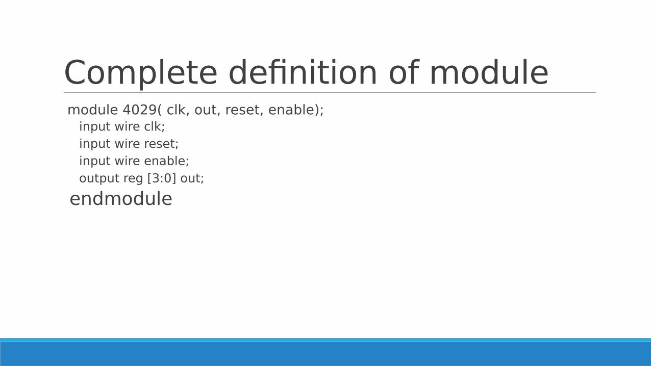
Complete definition of module module 4029( clk, out, reset, enable);
input wire clk; input wire reset; input wire enable; output reg [3:0] out;
endmodule
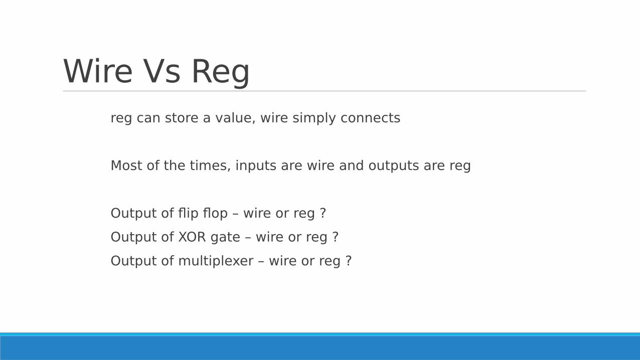
Wire Vs Reg reg can store a value, wire simply connects
Most of the times, inputs are wire and outputs are reg
Output of flip flop – wire or reg ?
Output of XOR gate – wire or reg ?
Output of multiplexer – wire or reg ?

What now? We have seen how to define the outer structure of the modules we will use.
Time to define the internal structure and functioning?

Operational and Conditional Statements
All the arithmetic as well as logical operators in Verilog are similar to C, except ++ and –- which are not available in Verilog.
Conditional statements are also similar to C with following modifications: ◦ { is replaced by begin.
◦ } is replaced by end.

Combinatorial Circuits Combinational circuits are acyclic interconnections of gates.
◦ And, Or, Not, Xor, Nand, Nor ……
◦ Multiplexers, Decoders, Encoders ….
◦ Adders, Multipliers ….
OUTPUT DEPENDS ON THE PRESENT INPUT ONLY.
How are these gates, muxs etc. abstracted in Verilog? ◦ Gates, Add, Multiply … : by simple operators like in C
◦ Multiplexers … : by control statements like if-else, case, etc.
Gate level implementation of above high level operators done by Verilog synthesizer.

Control Statements if-else, case :
◦ Exactly like C.
◦ Hardware view: implemented using multiplexers
for loops, repeat: ◦ – for-loops are synthesizable only if length of iteration is determined
at compile time & finite.
◦ repeat -similar to for loop.
◦ Hardware view: All loops are unrolled during synthesis.
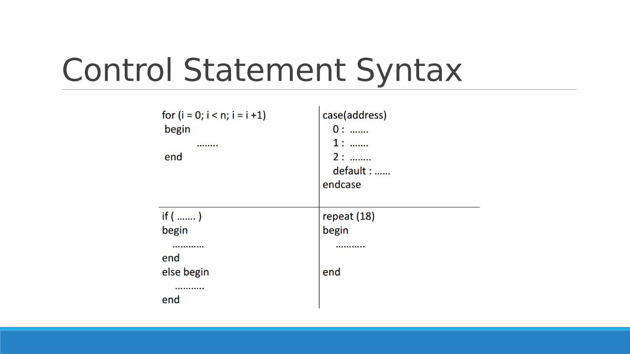
Control Statement Syntax

Assign statements Continuous assignment statement.
Used for modeling only combinational logic.
module BusInverter( input wire A, output wire B );
assign B = ~A;
endmodule
Basically B is shorted to ~A.
RHS should have variable of wire type.

Example-1 bit Full AdderGATE LEVEL DESCRIPTION
module full_adder(
input wire a,
input wire b,
input wire cin,
output wire sum,
output wire carry );
assign sum = a & ~b & ~cin | ~a & b & ~cin |~a & ~b & cin | a & b & cin;
assign carry = a & b | a & cin | b & cin;
endmodule
BEHAVIORAL DESCRIPTION
module full_adder(
input wire a,
input wire b,
input wire cin,
output wire sum,
output wire carry );
assign { carry, sum } = a+b+cin;
endmodule

Sequential Circuits Circuits containing state elements are called sequential circuits
OUTPUT DEPENDS ON THE PRESENT INPUT AS WELL AS ON ITS PRESENT STATE.
The simplest synchronous state element: Edge triggered D Flip Flop
How do you implement such an element in Verilog?

always @ block It is an abstraction provided in Verilog to mainly implement sequential circuits.
Also used for combinational circuits.
always @(#sensitivity list#)
begin
………. //No assign statements inside always@
end
Execution of always block depends on the sensitivity list.

Sensitivity List Run continuously. (mostly used in Test Benches)
always
Run when any variable changes its value.
always @(*) //for combinational ckts
Run when the variables `a' or `b' change their value.
always @(a, b)
Run when a positive edge is detected on CLK.
always @(posedge CLK) //for sequential ckt

initial block An initial block is executed only once when simulation starts
This is useful in writing test benches
If we have multiple initial blocks, then all of them are executed at the beginning of simulation

Counter Examplemodule Counter(
input wire CLK,
output reg [3:0] OUT );
initial
OUT <= 0;
always @(posedge CLK)
OUT <= OUT + 1;
endmodule

Blocking and Non-blocking statement
Non-blocking assignments happen in parallel.
always @ ( #sensitivity list # ) begin
B <= A ;
C <= B ; // (A,B) = (1,2) -> (B,C) = (1,2)
end
Blocking assignments happen sequentially.
always @ ( #sensitivity list # ) begin
B = A ;
C = B ; // (A,B) = (1,2) -> (B,C) = (1,1)
end

Points to note Use always@(*) block with blocking assignments for combinational circuits.
Use always@(posedge clk) block with non- blocking assignments for sequential combinational circuits.
Do not mix blocking and non-blocking statements.

Complete 4029 modulemodule 4029( clk, out, reset, enable);
input wire clk;
input wire reset;
input wire enable;
output reg [3:0] out;
always @(posedge clk)
begin
if (reset == 0 && enable == 0)
begin
out <= out +1;
end
end
// continued to next page
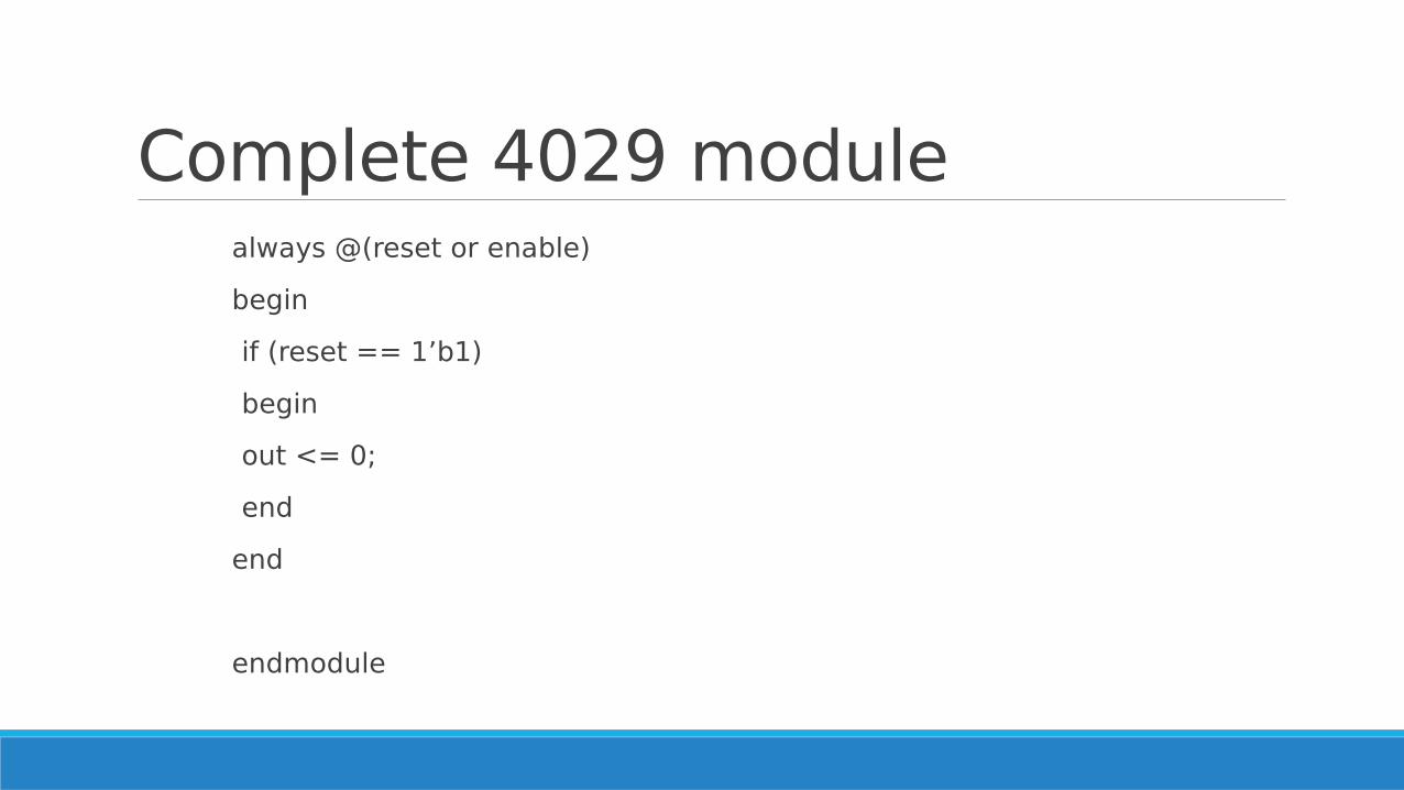
Complete 4029 modulealways @(reset or enable)
begin
if (reset == 1’b1)
begin
out <= 0;
end
end
endmodule

Xilinx Virtex V

Hobbyist Friendly Boards
Mojo v3/v2 Papilio Pro

How to get started? First of all download Xilinx ISE WebPack, with a free licence.
Create a simple project, and learn to write test benches (or directly create them on the ISE), and start using the ISim tool.
Do the ‘Verilog in a Day’ exercises found herehttp://www.asic-world.com/
Check if Mojo boards are available in club.
Go here: http://embeddedmicro.com/tutorials/mojo/
See your code in action!