introduction to electronics, 2 - mit opencourseware
TRANSCRIPT
MAS836 – Sensor Technologies for Interactive Environments
Original images © source unknown. All rights reserved. This content is excluded from our Creative Commons license. For more information, see http://ocw.mit.edu/fairuse.
Lecture 2 – Analog Conditioning Electronics, Pt. 2

2
JAP2/04
Reading…
• Horowitz and Hill – Finish Chapter 1, read Chapters 4&5
• Fraden – Interface Electronic Circuits Chapter (Chapter 4
of second edition)

3
JAP2/04
Reactive Impedance
• The Capacitor – Adds in parallel like resistors add in series – Reciprocal-adds in series like resistors add in parallel
• Impedance of capacitor = -j/ωC = -j/(2πfC) – Pass AC, block DC
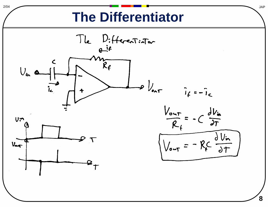
• Capacitor current: Ic = CdV/dt
• Impedance of inductor = jωL = j(2πfL) – Block AC, pass DC
• Inductor Voltage: V = LdI/dt
© Unknown. All rights reserved. This contentis excluded from our Creative Commons license.For more information, see http://ocw.mit.edu/fairuse.

4
JAP2/04
Passive RC Filters • Passive LP Filter: RC network: f = 1/(2πRC) c
-3dB = 0.707
This image is public domain.
This image is public domain. Frequency response of a high-pass filter.
© Cambridge University Press. All rights reserved. This content is excluded from our Creative Commons license. For more information, see http://ocw.mit.edu/fairuse.
• Passive HP filter: RC network: fc = 1/(2πRC)
1.0
ω 3dB = 1RC
Vout
Vin
0 ω
Vout
Vin~ ω (6dB/octave)
Image by MIT OpenCourseWare.

2/04 JAP
Passive RC Filter Rolloff
The rest of this figure has been removed due to copyright restrictions. It can be viewed on page 38 of The Art of Electronics, P. Horowitz and W. Hill. See: page 38 of The Art of Electronics on Google Books.
Bode Plot:Freq. Response as a log-log plot
Rolloff is 6 dB per Octave (2x) 20 dB per Decade (10x)
© Cambridge University Press. All rights reserved. This content is excluded from our Creative Commons license. For more information, see http://ocw.mit.edu/fairuse.
5

6
JAP2/04
Passive RLC Filters • Resonant parallel RLC bandpass filters
• Resonant series RLC notch filters
ZLC J ∞ @ f0
ZLC J 0 @ f0
Q = ω0(L/R) = f0/Δf3dB
Q = ω0RC = f0/Δf3dB
© Unknown. All rights reserved. This content is excluded from our Creative Commons license. For more information, see http://ocw.mit.edu/fairuse.

7
JAP2/04
Active Filters
• The Differentiator • The Active High-Pass Filter • Principle of Feedback Inversion • The Integrator • The Leaky Integrator (LP filter) • Buffered Passive Second-Order Filter • Sallen-Key (or VCVS) LP, HP, BP filters • Single-OpAmp VCVS BP filter
8
JAP2/04
The Differentiator

9
JAP2/04
The First-Order Active High Pass Filter
• Low impedance drive • Voltage gain via Rf/Ri

10
JAP2/04
The Integrator
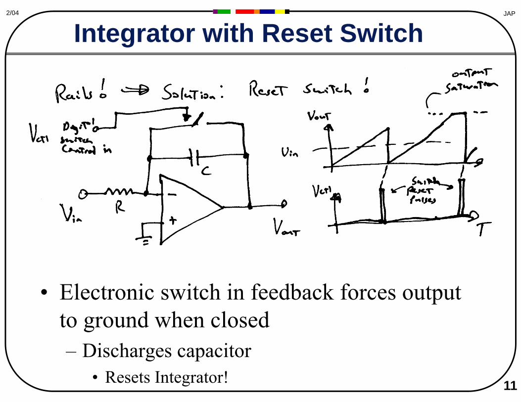
Saturates at rail!!
JAP2/04
Integrator with Reset Switch
• Electronic switch in feedback forces output to ground when closed – Discharges capacitor
• Resets Integrator! 11

12
AP2/04 J
The First-Order Active Low Pass Filter
f

3
JAP2/04
The Band-Select Filter
• Cascaded high and low pass filters – Always follow high-pass with low-pass (noise)
• Low-Pass cutoff needs to be below high-pass cutoff!
– No Q, first-order rolloffs 1

JAP2/04
The State Variable Filter
• Analog Computer set up to solve a general Second-Order Differential Equation – Exhibits rolloff, damping, and resonance – Simultaneous low-pass, bandpass, high-pass, and notch outputs available 17

18
JAP2/04
Modulars are Analog Computers?
Compumedic Analog Computer from 1971
Photo of a Compumedic Analog Computer from 1971 removed due to copyright restrictions. See: Old-Computers.com Museum.

JAP2/04
Limitations on Filter Performance
– Multiple-OpAmp filters can attain higher Q’s than single-OpAmp filters– Faster OpAmp's work better too
• Accumulated Phase Shifts can cause oscillation!
• The choice of OpAmp affects how well a given filter will performs work better too
21
OpAmp s
© Elsevier. All rights reserved. This content is excluded from our Creative Commons license. For more information, see http://ocw.mit.edu/fairuse.

JAP2/04
Voltage-Controlled Filter
• Replace integrator input resistors with 2-quadrant multipliers (voltage-controlled amplifiers, or VCA’s) – Need to tune both VCA’s together
• Results in a wide-range tunable filter! 22 – Multiplier can be used to tune Q as well
© Elsevier. All rights reserved. This content is excluded from our Creative Commons license. For more information, see http://ocw.mit.edu/fairuse.

JAP2/04
Switched-Capacitor Tunable Filters
• R is effectively varied proportionally to the On/Off duty cycle
– Beware of aliasing (max input frequency is under half the switching frequency)
– Not for High Pass filters! Tend to work best for lower-frequencies 23
• Many types of analog switches are available (e.g., ADG from Analog
Devices, etc.)
© Elsevier Science and Technology. All rights reserved. This content is excluded from our Creative Commons license. For more information, see http://ocw.mit.edu/fairuse.
© Elsevier Science and Technology. All rights reserved. This content is excluded from our Creative Commons license. For more information, see http://ocw.mit.edu/fairuse.

26
JAP2/04
Filters from Hong
Linear has come out with a couple really nice switched cap filters that really cuts down on the design time:
LTC1564 Tunable low pass filter 10kHz to 150kHz in steps of 10kHz, 8 pole roll-off, programmable 1-16 gain, 3-10V operation.
LTC1062 parallel 5-pole tunable low pass filter. Absolutely zero DC error because the input and output are connected directly with a wire and the filter damps out the high frequencies.

27
JAP2/04
Biasing
• AC Coupling • Biasing noninverting input • Biasing at inverting input

• The Diode – I/V characteristic, ideal diode, forward drop,
28
JAP2/04
Diodes
zeners Drops (Vd): Si = 0.6 V Ge = 0.3 V LED = 2.4-3.5 V Schottky = .1-.3 V
Vd
© Unknown. All rights reserved. This content is excluded from our Creative Commons license. For more information, see http://ocw.mit.edu/fairuse.

–Precision Zener
29
JAP2/04
Basic Diode Circuits
•Limiters/Clampers –Passive Limiter - normal and zener
Precision Clamper (servos out 0.6 V drop)
Zener Limiters
Positive Clamper
© Unknown. All rights reserved. This content is excluded from our Creative Commons license. For more information, see http://ocw.mit.edu/fairuse.

30
JAP2/04
Absolute Value Circuits
Bottom R is 2/3 top R in A1?
© Unknown. All rights reserved. This content is excluded from our Creative Commons license. For more information, see http://ocw.mit.edu/fairuse.
© Unknown. All rights reserved. This content is excluded from our Creative Commons license. For more information, see http://ocw.mit.edu/fairuse.

JAP2/04
Absolute Value Circuit (envelope follower)
• A1 and A2 form an absolute value detector • C6 integrates the absolute value to give the envelope • Note that the 748 (and its compensation cap) is long obsolete!
31
Vin
R539 K
R439 K
A2748
A3748
R8220 K
R639 K
R718 K
011N914
021N914
C6.05 µF
C4100 µF
C3100 µF
_
+
_
+1
8
Envelope out
Image by MIT OpenCourseWare.

32
JAP2/04
Peak Detector
t
t
Vs
Vo
Capacitor holds peaks! Need reset switch to continue tracking

JAP2/04
Pulse Stretcher
C RVVs
V t/RCe
Vo e-t/RC
t
-Resistor continually (and slowly) bleeds capacitor charg
-Automatic “reset”
-Tune time constant to match sigg ynal dynamics ((so ppeaks are
34
always followed)-Enables “lazy” sampling to catch transients

35
JAP2/04
Voltage Multipliers, etc.
Ref: Wikipedia… Transformer for isolation
- Diodes don’t let capacitors discharge onto source - AC coupling lets each peak sit atop capacitor voltage -Each AC peak increments voltage by half-wave height - Voltage drop at given current increases rapidly (cube) with no. stages, inversely with C, freq
Cascaded Villard doubler
© Unknown. All rights reserved. This content is excluded from our Creative Commons license. For more information, see http://ocw.mit.edu/fairuse.
36
JAP2/04
Sampling
• Nyquist: fin < fs/2 • Bandlimited (demodulation) sampling
– Δfin < fs/2 – Loose absolute phase information
• Don’t know whether phase moves forward or backward
– Quadrature sampling • Bandlimited sampling at t and a quarter-
period later
37
JAP2/04
Sampling Aids
• Aliasing for nonperiodic signals?? – Can miss or miss-sample trasients! – The Pulse-stretcher to the rescue!
• Sample/Holds • Analog Multiplexers • Programmable Gain Amplifiers
(PGA’s) • Voltage-Controlled Amplifiers
(VCA’s)

38
JAP2/04
The Basic Sample-Hold Circuit

JAP2/04
The Sample-Hold (and Track-Hold)
• Sample-Hold grabs input signal and holds it upon receipt of a pulse edge
• Track-Hold follows the input signal when the gate is high, but holds (latches) it when the gate is low.
• Sample hold acquires quickly – can use slow ADC. 39
© Unknown. All rights reserved. This content is excluded from our Creative Commons license. For more information, see http://ocw.mit.edu/fairuse.

41
JAP2/04
Analog Multiplexers
Courtesy of Analog Devices. Used with permission.

42
JAP2/04
Programmable Gain Amplifiers
Courtesy of Burr-Brown. Used with permission.

43
JAP2/04
Front end of the OTA OTAs have current outputs Ictot = ic1 +ic2 = βiCTL
Increasing +VIN increases ic1, which decreases ic2 (for fixed -VIN) since the sum of ic1 and ic2 must
LM13700 Datasheet equal icTOT
icTOT is proportional to iCTL, and the voltage across the collector resistors is proportional to icTOT, hence the gain of this circuit is set by icTOT
© Unknown. All rights reserved. This content is excluded from our Creative Commons license. For more information, see http://ocw.mit.edu/fairuse.
MTU ECE Diff Amp Notes
© National Semiconductor. All rights reserved. This content is excluded from our Creative Commons license. For more information, see http://ocw.mit.edu/fairuse.

44
JAP2/04
Voltage Controlled Amplifiers
VCA output for sinusoidal input and given control voltage
Vout = Vin * Vctl (or 0 if Vctl < 0)
© Unknown. All rights reserved. This content is excluded from our Creative Commons license. For more information, see http://ocw.mit.edu/fairuse.

45
JAP2/04
Voltage-Controlled Amplifiers (VCA)
Also AD603
Courtesy of Burr-Brown. Used with permission. Courtesy of Analog Devices. Used with permission.
47
JAP2/04
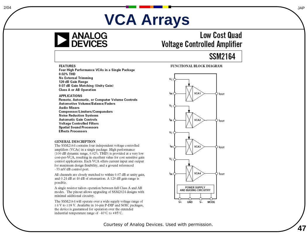
VCA Arrays
Courtesy of Analog Devices. Used with permission.
48
JAP2/04
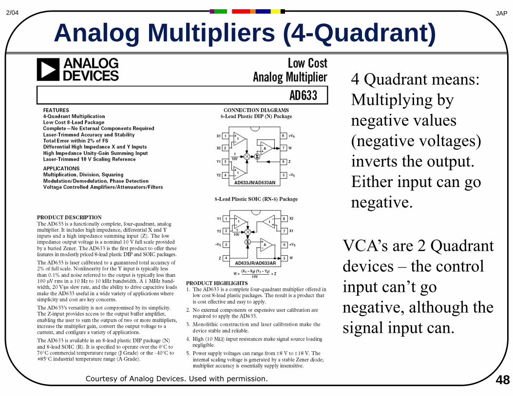
Analog Multipliers (4-Quadrant) 4 Quadrant means: Multiplying by negative values (negative voltages) inverts the output. Either input can go negative.
VCA’s are 2 Quadrant devices – the control input can’t go negative, although the signal input can.
Courtesy of Analog Devices. Used with permission.
MIT OpenCourseWarehttp://ocw.mit.edu
MAS.836 Sensor Technologies for Interactive Environments Spring 2011
For information about citing these materials or our Terms of Use, visit: http://ocw.mit.edu/terms.