introduction to compilers and language design …dthain/compilerbook/chapter10.pdf147 chapter 10 –...
TRANSCRIPT

Introduction to Compilers and Language DesignCopyright © 2020 Douglas Thain.Second edition.
Anyone is free to download and print the PDF edition of this book for per-sonal use. Commercial distribution, printing, or reproduction without theauthor’s consent is expressly prohibited. All other rights are reserved.
You can find the latest version of the PDF edition, and purchase inexpen-sive hardcover copies at http://compilerbook.org
Revision Date: June 18, 2020
149
Chapter 10 – Assembly Language
10.1 Introduction
In order to build a compiler, you must have a working knowledge of atleast one kind of assembly language. And, it helps to see two or morevariations of assembly, so as to fully appreciate the distinctions betweenarchitectures. Some of these differences, such as register structure, arequite fundamental, while some of the differences are merely superficial.
We have observed that many students seem to think that assembly lan-guage is rather obscure and complicated. Well, it is true that the completemanual for a CPU is extraordinarily thick, and may document hundredsof instructions and obscure addressing modes. However, it’s been our ex-perience that it is really only necessary to learn a small subset of a givenassembly language (perhaps 30 instructions) in order to write a functionalcompiler. Many of the additional instructions and features exist to handlespecial cases for operating systems, floating point math, and multi-mediacomputing. You can do almost everything needed with the basic subset.
We will look at two different CPU architectures that are in wide use to-day: X86 and ARM. The Intel X86 is a CISC architecture that has evolvedsince the 1970s from 8-bit to 64-bit and is now the dominant chip in per-sonal computers, laptops, and high performance servers. The ARM pro-cessor is a RISC architecture began life as a 32-bit chip for the personalcomputer market, and is now the dominant chip for low-power and em-bedded devices such as mobile phones and tablets.
This chapter will give you a working knowledge of the basics of eacharchitecture, but you will need a good reference to look up more details.We recommend that you consult the Intel Software Developer Manual [1]and the ARM Architecture Reference Manual [3] for the complete details.(Note that each section is meant to be parallel and self-contained, so someexplanatory material is repeated for both X86 and ARM.)
149

150 CHAPTER 10. ASSEMBLY LANGUAGE
10.2 Open Source Assembler Tools
A given assembly language can have multiple dialects for the same CPU,depending on whether one uses the assembler provided by the chip ven-dor, or other open source tools. For consistency, we will give examplesin the assembly dialect supported by the GNU compiler and assembler,which are known as gcc and as (or sometimes gas).
A good way to get started is to view the assembler output of the com-piler for a C program. To do this, run gcc with the -S flag, and thecompiler will produce assembly output rather than a binary program. OnUnix-like systems, assembly code is stored in files ending with .s, whichindicates “source” file.
If you run gcc -S hello.c -o hello.s on this C program:
#include <stdio.h>
int main( int argc, char *argv[] )
{
printf("hello %s\n","world");
return 0;
}
then you should see output similar to this in hello.s
.file "test.c"
.data
.LC0:
.string "hello %s\n"
.LC1:
.string "world"
.text
.global main
main:
PUSHQ %rbp
MOVQ %rsp, %rbp
SUBQ $16, %rsp
MOVQ %rdi, -8(%rbp)
MOVQ %rsi, -16(%rbp)
MOVQ $.LC0, %rax
MOVQ $.LC1, %rsi
MOVQ %rax, %rdi
MOVQ $0, %rax
CALL printf
MOVQ $0, %rax
LEAVE
RET
150

10.2. OPEN SOURCE ASSEMBLER TOOLS 151
(There are many valid ways to compile hello.c and so the output ofyour compiler may be somewhat different.)
Regardless of the CPU architecture, the assembly code has three differ-ent kinds of elements:
Directives begin with a dot and indicate structural information use-ful to the assembler, linker, or debugger, but are not in and of themselvesassembly instructions. For example, .file simply records the name ofthe original source file to assist the debugger. .data indicates the start ofthe data segment of the program, while .text indicates the start of theprogram segment. .string indicates a string constant within the datasection, and .global main indicates that the label main is a global sym-bol that can be accessed by other code modules.
Labels end with a colon and indicate by their position the associationbetween names and locations. For example, the label .LC0: indicates thatthe immediately following string should be called .LC0. The label main:indicates that the instruction PUSHQ %rbp is the first instruction of themain function. By convention, labels beginning with a dot are temporarylocal labels generated by the compiler, while other symbols are user-visiblefunctions and global variables. The labels do not become part of the result-ing machine code per se, but they are present in the resulting object codefor the purposes of linking, and in the eventual executable, for purposesof debugging.
Instructions are the actual assembly code like (PUSHQ %rbp), typicallyindented to visually distinguish them from directives and labels. Instruc-tions in GNU assembly are not case sensitive, but we will generally upper-case them, for consistency.
To take this hello.s and turn it into a runnable program, just rungcc, which will figure out that it is an assembly program, assemble it, andlink it with the standard library:
% gcc hello.s -o hello
% ./hello
hello world
It is also interesting to compile the assembly code into object code, andthen use the nm utility to display the symbols (”names”) present in thecode:
% gcc hello.s -c -o hello.o
% nm hello.o
0000000000000000 T main
U printf
This displays the information available to the linker. main is present inthe text (T) section of the object, at location zero, and printf is undefined
151

152 CHAPTER 10. ASSEMBLY LANGUAGE
(U), since it must be obtained from the standard library. But none of thelabels like .LC0 appear because they were not declared as .global.
As you are learning assembly language, take advantage of an existingcompiler: write some simple functions to see what gcc generates. This cangive you some starting points to identify new instructions and techniquesto use.
10.3 X86 Assembly Language
X86 is a generic term that refers to the series of microprocessors descendedfrom (or compatible with) the Intel 8088 processor used in the original IBMPC, including the 8086, 80286, ’386, ’486, and many others. Each genera-tion of CPUs added new instructions and addressing modes from 8-bit to16-bit to 32-bit, all while retaining backwards compatibility with old code.A variety of competitors (such as AMD) produced compatible chips thatimplemented the same instruction set.
However, Intel broke with tradition in the 64-bit generation by intro-ducing a new brand (Itanium) and architecture (IA64) that was not back-wards compatible with old code. Instead, it implemented a new conceptknown as Very Long Instruction Word (VLIW) in which multiple concur-rent operations were encoded into a single word. This had the potential forsignificant speedups due to instruction-level parallelism but representeda break with the past.
AMD stuck with the old ways and produced a 64-bit architecture (AMD64)that was backwards compatible with both Intel and AMD chips. While thetechnical merits of both approaches were debatable, the AMD approachwon in the marketplace, and Intel followed by producing its own 64-bitarchitecture (Intel64) that was compatible with AMD64 and its own pre-vious generation of chips. X86-64 is the generic name that covers bothAMD64 and Intel64 architectures.
X86-64 is a fine example of CISC (complex instruction set computing).There are a very large number of instructions with many different sub-modes, some of them designed for very narrow tasks. However, a smallsubset of instructions will let us accomplish a lot.
10.3.1 Registers and Data Types
X86-64 has sixteen (almost) general purpose 64-bit integer registers:
%rax %rbx %rcx %rdx %rsi %rdi %rbp %rsp%r8 %r9 %r10 %r11 %r12 %r13 %r14 %r15
These registers are almost general purpose because earlier versions ofthe processors intended for each register to be used for a specific purpose,and not all instructions could be applied to every register. The names of
152

10.3. X86 ASSEMBLY LANGUAGE 153
A Note on AT&T Syntax versus Intel Syntax
Note that the GNU tools use the traditional AT&T syntax, which is usedacross many processors on Unix-like operating systems, as opposed to theIntel syntax typically used on DOS and Windows systems. The followinginstruction is given in AT&T syntax:
MOVQ %RSP, %RBP
MOVQ is the name of the instruction, and the percent signs indicate thatRSP and RBP are registers. In the AT&T syntax, the source is always givenfirst, and the destination is always given second.
In other places (such as the Intel manual), you will see the Intel syntax,which (among other things) dispenses with the percent signs and reversesthe order of the arguments. For example, this is the same instruction in theIntel syntax:
MOVQ RBP, RSP
When reading manuals and web pages, be careful to determine whetheryou are looking at AT&T or Intel syntax: look for the percent signs!
the lower eight registers indicate the purpose for which each was origi-nally intended: for example, %rax is the accumulator.
As the design developed, new instructions and addressing modes wereadded to make the various registers almost equal. A few remaining in-structions, particularly related to string processing, require the use of %rsiand %rdi. In addition, two registers are reserved for use as the stackpointer (%rsp) and the base pointer (%rbp). The final eight registers arenumbered and have no specific restrictions.
The architecture has expanded from 8 to 64 bits over the years, and soeach register has some internal structure. The lowest 8 bits of the %raxregister are an 8-bit register %al, and the next 8 bits are known as %ah.The low 16 bits are collectively known as %ax, the low 32-bits as %eax,and the whole 64 bits as %rax.
Figure 10.1: X86 Register Structure
8 bits: al ah16 bits: ax32 bits: eax64 bits: rax
153
154 CHAPTER 10. ASSEMBLY LANGUAGE
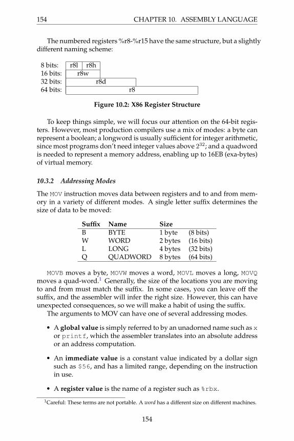
The numbered registers %r8-%r15 have the same structure, but a slightlydifferent naming scheme:
8 bits: r8l r8h16 bits: r8w32 bits: r8d64 bits: r8
Figure 10.2: X86 Register Structure
To keep things simple, we will focus our attention on the 64-bit regis-ters. However, most production compilers use a mix of modes: a byte canrepresent a boolean; a longword is usually sufficient for integer arithmetic,since most programs don’t need integer values above 232; and a quadwordis needed to represent a memory address, enabling up to 16EB (exa-bytes)of virtual memory.
10.3.2 Addressing Modes
The MOV instruction moves data between registers and to and from mem-ory in a variety of different modes. A single letter suffix determines thesize of data to be moved:
Suffix Name Size
B BYTE 1 byte (8 bits)W WORD 2 bytes (16 bits)L LONG 4 bytes (32 bits)Q QUADWORD 8 bytes (64 bits)
MOVB moves a byte, MOVW moves a word, MOVL moves a long, MOVQmoves a quad-word.1 Generally, the size of the locations you are movingto and from must match the suffix. In some cases, you can leave off thesuffix, and the assembler will infer the right size. However, this can haveunexpected consequences, so we will make a habit of using the suffix.
The arguments to MOV can have one of several addressing modes.
• A global value is simply referred to by an unadorned name such as xor printf, which the assembler translates into an absolute addressor an address computation.
• An immediate value is a constant value indicated by a dollar signsuch as $56, and has a limited range, depending on the instructionin use.
• A register value is the name of a register such as %rbx.
1Careful: These terms are not portable. A word has a different size on different machines.
154
10.3. X86 ASSEMBLY LANGUAGE 155
• An indirect value refers to a value by the address contained in aregister. For example, (%rsp) refers to the value pointed to by %rsp.
• A base-relative value is given by adding a constant to the name ofa register. For example, -16(%rcx) refers to the value at the mem-ory location sixteen bytes below the address indicated by %rcx. Thismode is important for manipulating stacks, local values, and func-tion parameters, where the start of an object is given by a register.
• A complex address is of the form D(RA, RB , C) which refers to thevalue at address RA + RB ∗ C + D. Both RA and RB are generalpurpose registers, while C can have the value 1, 2, 4, or 8, and D
can be any integer displacement. This mode is used to select an itemwithin an array, where RA gives the base of the array, RB gives theindex into the array, C gives the size of the items in the array, and D
is an offset relative to that item.
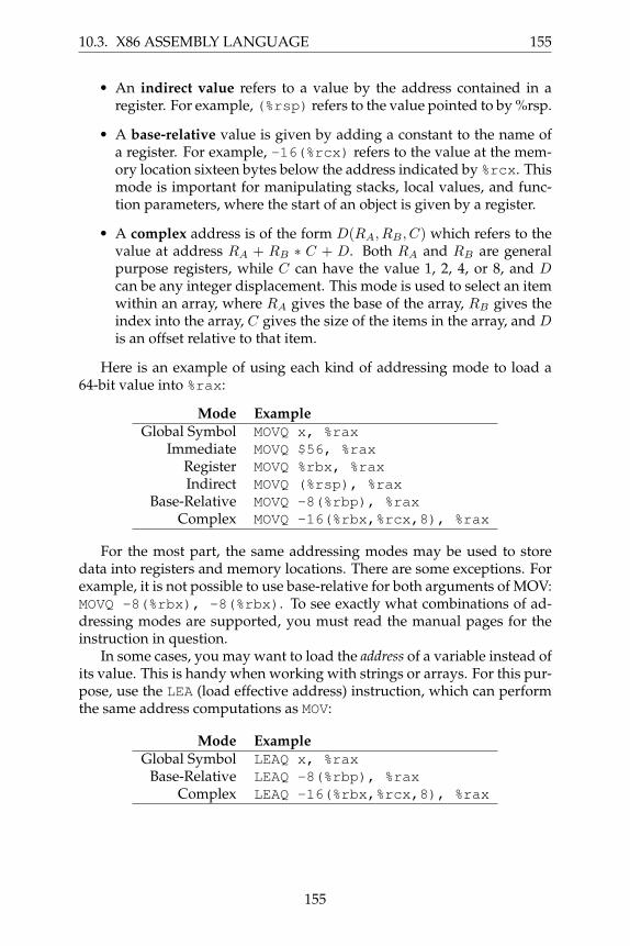
Here is an example of using each kind of addressing mode to load a64-bit value into %rax:
Mode Example
Global Symbol MOVQ x, %rax
Immediate MOVQ $56, %rax
Register MOVQ %rbx, %rax
Indirect MOVQ (%rsp), %rax
Base-Relative MOVQ -8(%rbp), %rax
Complex MOVQ -16(%rbx,%rcx,8), %rax
For the most part, the same addressing modes may be used to storedata into registers and memory locations. There are some exceptions. Forexample, it is not possible to use base-relative for both arguments of MOV:MOVQ -8(%rbx), -8(%rbx). To see exactly what combinations of ad-dressing modes are supported, you must read the manual pages for theinstruction in question.
In some cases, you may want to load the address of a variable instead ofits value. This is handy when working with strings or arrays. For this pur-pose, use the LEA (load effective address) instruction, which can performthe same address computations as MOV:
Mode Example
Global Symbol LEAQ x, %rax
Base-Relative LEAQ -8(%rbp), %rax
Complex LEAQ -16(%rbx,%rcx,8), %rax
155

156 CHAPTER 10. ASSEMBLY LANGUAGE
10.3.3 Basic Arithmetic
You will need four basic arithmetic instructions for your compiler: integeraddition, subtraction, multiplication, and division.
ADD and SUB have two operands: a source and a destructive target.For example, this instruction:
ADDQ %rbx, %rax
adds %rbx to %rax, and places the result in %rax, overwriting what mighthave been there before. This requires a little care, so that you don’t acci-dentally clobber a value that you might want to use later. For example,you could translate c = a+b+b; like this:
MOVQ a, %rax
MOVQ b, %rbx
ADDQ %rbx, %rax
ADDQ %rbx, %rax
MOVQ %rax, c
The IMUL instruction is a little unusual, because multiplying two 64-bit integers results in a 128-bit integer, in the general case. IMUL takes itsargument, multiplies it by the contents of %rax, and then places the low64 bits of the result in %rax and the high 64 bits in %rdx. (This is implicit:%rdx is not mentioned in the instruction.)
For example, suppose that you wish to translate c = b*(b+a);, wherea, and b, and c are global integers. Here is one possible translation:
MOVQ a, %rax
MOVQ b, %rbx
ADDQ %rbx, %rax
IMULQ %rbx
MOVQ %rax, c
The IDIV instruction does the same thing, except backwards: it startswith a 128 bit integer value whose low 64 bits are in %rax and high 64 bitsin %rdx, and divides it by the value given in the instruction. The quotientis placed in %rax and the remainder in %rdx. (If you want to implementthe modulus instruction instead of division, just use the value of %rdx.)
To set up a division, you must make sure that both registers have thenecessary sign-extended value. If the dividend fits in the lower 64 bits, butis negative, then the upper 64 bits must all be ones to complete the twos-complement representation. The CQO instruction serves the very specificpurpose of sign-extending %rax into %rdx for division.
For example, to divide a by five:
156

10.3. X86 ASSEMBLY LANGUAGE 157
MOVQ a, %rax # set the low 64 bits of the dividend
CQO # sign-extend %rax into %rdx
IDIVQ $5 # divide %rdx:%rax by 5,
# leaving result in %rax
The instructions INC and DEC increment and decrement a register de-structively. For example, the statement a = ++b could be translated as:
MOVQ b, %rax
INCQ %rax
MOVQ %rax,b
MOVQ %rax, a
The instructions AND, OR, and XOR perform destructive bitwise booleanoperations on two values. Bitwise means that the operation is applied toeach individual bit in the operands, and stored in the result.So, AND $0101B $0110B would yield the result $0100B. In a similarway, the NOT instruction inverts each bit in the operand. For example,the bitwise C expression c = (a & ˜b); could be translated like this:
MOVQ a, %rax
MOVQ b, %rbx
NOTQ %rbx
ANDQ %rax, %rbx
MOVQ %rbx, c
Be careful here: these instructions do not implement logical boolean op-erations according to the C representation that you are probably familiarwith. For example, if you define “false” to be the integer zero, and “true”to be any non-zero value. In that case, $0001 is true, but NOT $0001B is$1110B, which is also true! To implement that correctly, you need to useCMP with conditionals described below.2
Like the MOV instruction, the various arithmetic instructions can workon a variety of addressing modes. However, for your compiler project, youwill likely find it most convenient to use MOV to load values in and out ofregisters, and then use only registers to perform arithmetic.
2Alternatively, you could could use the bitwise operators as logical operators if you givetrue the integer value -1 (all ones) and false the integer value zero.
157

158 CHAPTER 10. ASSEMBLY LANGUAGE
10.3.4 Comparisons and Jumps
Using the JMP instruction, we may create a simple infinite loop that countsup from zero using the %rax register:
MOVQ $0, %rax
loop: INCQ %rax
JMP loop
To define more useful structures such as terminating loops and if-thenstatements, we must have a mechanism for evaluating values and chang-ing program flow. In most assembly languages, these are handled by twodifferent kinds of instructions: compares and jumps.
All comparisons are done with the CMP instruction. CMP comparestwo different registers and then sets a few bits in the internal EFLAGSregister, recording whether the values are the same, greater, or lesser. Youdon’t need to look at the EFLAGS register directly. Instead a selection ofconditional jumps examine the EFLAGS register and jump appropriately:
Instruction Meaning
JE Jump if EqualJNE Jump if Not EqualJL Jump if LessJLE Jump if Less or EqualJG Jump if GreaterJGE Jump if Greater or Equal
For example, here is a loop to count %rax from zero to five:
MOVQ $0, %rax
loop: INCQ %rax
CMPQ $5, %rax
JLE loop
And here is a conditional assignment: if global variable x is greaterthan zero, then global variable y gets ten, else twenty:
MOVQ x, %rax
CMPQ $0, %rax
JLE .L1
.L0:
MOVQ $10, $rbx
JMP .L2
.L1:
MOVQ $20, $rbx
.L2:
MOVQ %rbx, y
158

10.3. X86 ASSEMBLY LANGUAGE 159
Note that jumps require the compiler to define target labels. Theselabels must be unique and private within one assembly file, but cannot beseen outside the file unless a .global directive is given. Labels like .L0,.L1, etc, can be generated by the compiler on demand.
10.3.5 The Stack
The stack is an auxiliary data structure used primarily to record the func-tion call history of the program along with local variables that do not fitin registers. By convention, the stack grows downward from high valuesto low values. The %rsp register is known as the stack pointer and keepstrack of the bottom-most item on the stack.
To push %rax onto the stack, we must subtract 8 (the size of %rax inbytes) from %rsp and then write to the location pointed to by %rsp:
SUBQ $8, %rsp
MOVQ %rax, (%rsp)
Popping a value from the stack involves the opposite:
MOVQ (%rsp), %rax
ADDQ $8, %rsp
To discard the most recent value from the stack, just move the stackpointer the appropriate number of bytes :
ADDQ $8, %rsp
Of course, pushing to and popping from the stack referred to by %rspis so common, that the two operations have their own instructions thatbehave exactly as above:
PUSHQ %rax
POPQ %rax
Note that, in 64-bit code, PUSH and POP are limited to working with64-bit values, so a manual MOV and ADD must be used if it is necessary tomove smaller items to/from the stack.
159
160 CHAPTER 10. ASSEMBLY LANGUAGE
10.3.6 Calling a Function
Prior to the 64-bit architecture described here, a simple stack calling con-vention was used: arguments were pushed on the stack in reverse order,then the function was invoked with CALL. The called function looked forthe arguments on the stack, did its work, and returned the result in %eax.The caller then removed the arguments from the stack.
However, 64-bit code uses a register calling convention, in order to ex-ploit the larger number of available registers in the X86-64 architecture. 3
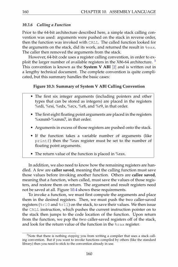
This convention is known as the System V ABI [2] and is written out ina lengthy technical document. The complete convention is quite compli-cated, but this summary handles the basic cases:
Figure 10.3: Summary of System V ABI Calling Convention
• The first six integer arguments (including pointers and othertypes that can be stored as integers) are placed in the registers%rdi, %rsi, %rdx, %rcx, %r8, and %r9, in that order.
• The first eight floating point arguments are placed in the registers%xmm0-%xmm7, in that order.
• Arguments in excess of those registers are pushed onto the stack.
• If the function takes a variable number of arguments (likeprintf) then the %rax register must be set to the number offloating point arguments.
• The return value of the function is placed in %rax.
In addition, we also need to know how the remaining registers are han-dled. A few are caller saved, meaning that the calling function must savethose values before invoking another function. Others are callee saved,meaning that a function, when called, must save the values of those regis-ters, and restore them on return. The argument and result registers neednot be saved at all. Figure 10.4 shows these requirements.
To invoke a function, we must first compute the arguments and placethem in the desired registers. Then, we must push the two caller-savedregisters (%r10 and %r11) on the stack, to save their values. We then issuethe CALL instruction, which pushes the current instruction pointer on tothe stack then jumps to the code location of the function. Upon returnfrom the function, we pop the two caller-saved registers off of the stack,and look for the return value of the function in the %rax register.
3Note that there is nothing stopping you from writing a compiler that uses a stack call-ing convention. But if you want to invoke functions compiled by others (like the standardlibrary) then you need to stick to the convention already in use.
160
10.3. X86 ASSEMBLY LANGUAGE 161
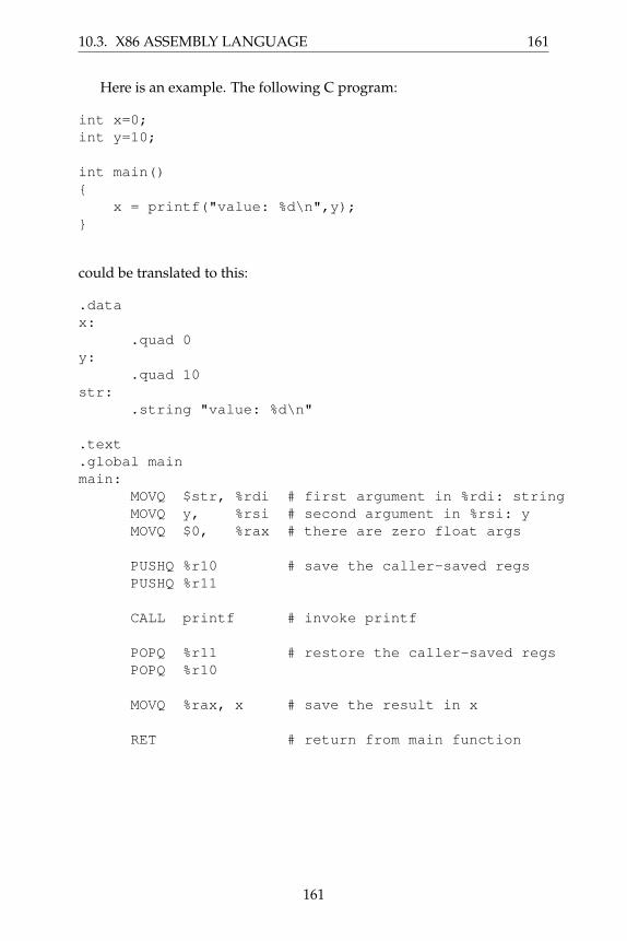
Here is an example. The following C program:
int x=0;
int y=10;
int main()
{
x = printf("value: %d\n",y);
}
could be translated to this:
.data
x:
.quad 0
y:
.quad 10
str:
.string "value: %d\n"
.text
.global main
main:
MOVQ $str, %rdi # first argument in %rdi: string
MOVQ y, %rsi # second argument in %rsi: y
MOVQ $0, %rax # there are zero float args
PUSHQ %r10 # save the caller-saved regs
PUSHQ %r11
CALL printf # invoke printf
POPQ %r11 # restore the caller-saved regs
POPQ %r10
MOVQ %rax, x # save the result in x
RET # return from main function
161

162 CHAPTER 10. ASSEMBLY LANGUAGE
Figure 10.4: System V ABI Register Assignments
Register Purpose Who Saves?
%rax result not saved%rbx scratch callee saves%rcx argument 4 not saved%rdx argument 3 not saved%rsi argument 2 not saved%rdi argument 1 not saved%rbp base pointer callee saves%rsp stack pointer callee saves%r8 argument 5 not saved%r9 argument 6 not saved%r10 scratch CALLER saves%r11 scratch CALLER saves%r12 scratch callee saves%r13 scratch callee saves%r14 scratch callee saves%r15 scratch callee saves
10.3.7 Defining a Leaf Function
Because function arguments are passed in registers, it is easy to write aleaf function that computes a value without calling any other functions.For example, code for the following function:
square: function integer ( x: integer ) =
{
return x*x;
}
Could be as simple as this:
.global square
square:
MOVQ %rdi, %rax # copy first argument to %rax
IMULQ %rax # multiply it by itself
# result is already in %rax
RET # return to caller
Unfortunately, this won’t work for a function that wants to invokeother functions, because we haven’t set up the stack properly. A morecomplex approach is needed for the general case.
162

10.3. X86 ASSEMBLY LANGUAGE 163
10.3.8 Defining a Complex Function
A complex function must be able to invoke other functions and computeexpressions of arbitrary complexity, and then return to the caller with theoriginal state intact. Consider the following recipe for a function that ac-cepts three arguments and uses two local variables:
.global func
func:
pushq %rbp # save the base pointer
movq %rsp, %rbp # set new base pointer
pushq %rdi # save first argument on the stack
pushq %rsi # save second argument on the stack
pushq %rdx # save third argument on the stack
subq $16, %rsp # allocate two more local variables
pushq %rbx # save callee-saved registers
pushq %r12
pushq %r13
pushq %r14
pushq %r15
### body of function goes here ###
popq %r15 # restore callee-saved registers
popq %r14
popq %r13
popq %r12
popq %rbx
movq %rbp, %rsp # reset stack pointer
popq %rbp # recover previous base pointer
ret # return to the caller
There is a lot to keep track of here: the arguments given to the function,the information necessary to return, and space for local computations. Forthis purpose, we use the base register pointer %rbp. Whereas the stackpointer %rsp points to the end of the stack where new data will be pushed,the base pointer %rbp points to the start of the values used by this func-tion. The space between %rbp and %rsp is known as the stack frame forthis function call.
163

164 CHAPTER 10. ASSEMBLY LANGUAGE
There is one more complication: each function needs to use a selectionof registers to perform computations. However, what happens when onefunction is called in the middle of another? We do not want any registerscurrently in use by the caller to be clobbered by the called function. Toprevent this, each function must save and restore all of the registers that ituses by pushing them onto the stack at the beginning, and popping themoff of the stack before returning. According to Figure 10.4, each functionmust preserve the values of %rsp, %rbp, %rbx, and %r12-%r15 when itcompletes.
Here is the stack layout for func, defined above:
Contents Addressold %rip register 8(%rbp)old %rbp register (%rbp) ←%rbp points hereargument 0 -8(%rbp)argument 1 -16(%rbp)argument 2 -24(%rbp)local variable 0 -32(%rbp)local variable 1 -40(%rbp)saved register %rbx -48(%rbp)saved register %r12 -56(%rbp)saved register %r13 -64(%rbp)saved register %r14 -72(%rbp)saved register %r15 -80(%rbp) ←%rsp points here
Figure 10.5: Example X86-64 Stack Layout
Note that the base pointer (%rbp) locates the start of the stack frame.So, within the body of the function, we may use base-relative address-ing against the base pointer to refer to both arguments and locals. Thearguments to the function follow the base pointer, so argument zero is at -8(%rbp), argument one at -16(%rbp), and so forth. Past those are local vari-ables to the function at -32(%rbp) and then saved registers at -48(%rbp).The stack pointer points to the last item on the stack. If we use the stackfor additional purposes, data will be pushed to further negative values.(Note that we have assumed all arguments and variables are 8 bytes large:different types would result in different offsets.)
164

10.3. X86 ASSEMBLY LANGUAGE 165
Here is a complete example that puts it all together. Suppose that youhave a B-minor function defined as follows:
compute: function integer
( a: integer, b: integer, c: integer ) =
{
x:integer = a+b+c;
y:integer = x*5;
return y;
}
A complete translation of the function is on the next page. The codegiven is correct, but rather conservative. As it turned out, this particularfunction didn’t need to use registers %rbx and %r15, so it wasn’t neces-sary to save and restore them. In a similar way, we could have kept thearguments in registers without saving them to the stack. The result couldhave been computed directly into %rax rather than saving it to a local vari-able. These optimizations are easy to make when writing code by hand,but not so easy when writing a compiler.
For your first attempt at building a compiler, your code created will(probably) not be very efficient if each statement is translated indepen-dently. The preamble to a function must save all the registers, because itdoes not know a priori which registers will be used later. Likewise, a state-ment that computes a value must save it back to a local variable, becauseit does not know beforehand whether the local will be used as a returnvalue. We will explore these issues later in Chapter 12 on optimization.
165

166 CHAPTER 10. ASSEMBLY LANGUAGE
Figure 10.6: Complete X86 Example.global compute
compute:
##################### preamble of function sets up stack
pushq %rbp # save the base pointer
movq %rsp, %rbp # set new base pointer to rsp
pushq %rdi # save first argument (a) on the stack
pushq %rsi # save second argument (b) on the stack
pushq %rdx # save third argument (c) on the stack
subq $16, %rsp # allocate two more local variables
pushq %rbx # save callee-saved registers
pushq %r12
pushq %r13
pushq %r14
pushq %r15
######################## body of function starts here
movq -8(%rbp), %rbx # load each arg into a register
movq -16(%rbp), %rcx
movq -24(%rbp), %rdx
addq %rdx, %rcx # add the args together
addq %rcx, %rbx
movq %rbx, -32(%rbp) # store the result into local 0 (x)
movq -32(%rbp), %rbx # load local 0 (x) into a register.
movq $5, %rcx # load 5 into a register
movq %rbx, %rax # move argument in rax
imulq %rcx # multiply them together
movq %rax, -40(%rbp) # store the result in local 1 (y)
movq -40(%rbp), %rax # move local 1 (y) into the result
#################### epilogue of function restores the stack
popq %r15 # restore callee-saved registers
popq %r14
popq %r13
popq %r12
popq %rbx
movq %rbp, %rsp # reset stack to base pointer.
popq %rbp # restore the old base pointer
ret # return to caller
166
10.4. ARM ASSEMBLY 167
10.4 ARM Assembly
The ARM processor architecture has a history almost as long as the X86architecture. It originated as the 32-bit Acorn RISC Machine used in theAcorn Archimedes personal computer in 1987, and has since evolved intoa wide-used low-power CPU employed in many embedded and mobilesystems, now known as the Advanced RISC Machine (ARM). The evolv-ing architecture has been implemented by a number of chip vendors work-ing from a common architecture definition. The most recent versions ofthe architecture are ARMv7-A (32-bit) and ARMv8-A (64-bit.) This chap-ter will focus on the 32-bit architecture, with some remarks on differencesin the 64-bit architecture at the end.
ARM is an example of a Reduced Instruction Set Computer (RISC)rather than a Complex Instruction Set Computer (CISC). Compared toX86, ARM relies on a smaller set of instructions which are simpler to pipelineor run in parallel, reducing the complexity and energy consumption of thechip. ARM is sometimes considered “partially” RISC due to a few ex-ceptions. For example, the difference in the time to execute some ARMinstruction makes the pipeline imperfect, the inclusion of a barrel shifterfor preprocessing brings forward more complex instructions, and condi-tional execution decreases some of the potential instructions executed andlead to less branching instructions so less energy used by the processor.We will mainly be focusing on the elements of the instruction set whichallow us to do the most in a compiler, leaving the more complex aspectsand optimizations of the programming language for later.
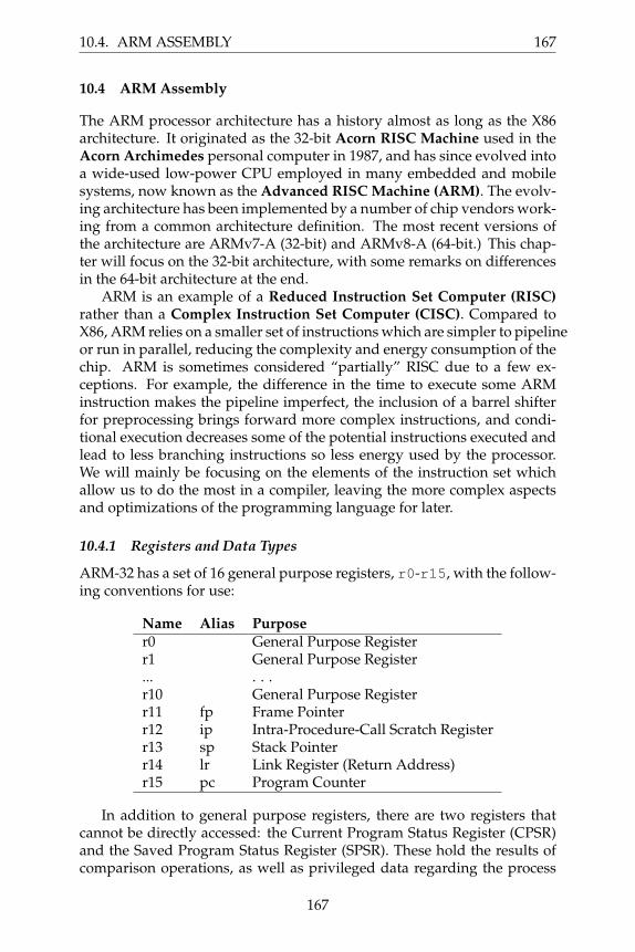
10.4.1 Registers and Data Types
ARM-32 has a set of 16 general purpose registers, r0-r15, with the follow-ing conventions for use:
Name Alias Purpose
r0 General Purpose Registerr1 General Purpose Register... . . .r10 General Purpose Registerr11 fp Frame Pointerr12 ip Intra-Procedure-Call Scratch Registerr13 sp Stack Pointerr14 lr Link Register (Return Address)r15 pc Program Counter
In addition to general purpose registers, there are two registers thatcannot be directly accessed: the Current Program Status Register (CPSR)and the Saved Program Status Register (SPSR). These hold the results ofcomparison operations, as well as privileged data regarding the process
167

168 CHAPTER 10. ASSEMBLY LANGUAGE
state. A user-level program cannot access these directly, but they can beset as a side effect of some operations.
ARM uses the following suffixes to indicate data sizes. Note that thesehave different meanings than in X86 assembly! If no suffix is given, theassembler assumes an unsigned word operand. Signed types are used toprovide appropriate sign-extension when loading a small data type into alarger register. There is no register naming structure for anything below aword.
Data Type Suffix Size
Byte B 8 bitsHalfword H 16 bitsWord W 32 bitsDouble Word - 64 bitsSigned Byte SB 8 bitsSigned Halfword SH 16 bitsSigned Word SW 32 bitsDouble Word - 64 bits
10.4.2 Addressing Modes
ARM makes the use of two different classes of instructions to move databetween registers and between registers and memory. MOV copies data andconstants between registers, while LDR (load) and STR (store) instructionsare used to move data between registers and memory.
The MOV instruction is used to move a known immediate value intoa given register or move another register into the first register. In ARM,immediate values are denoted by a #. However, these immediate valuesmust be 16-bits or less. If they are greater, the LDR instruction must beused instead. Most ARM instructions indicate the destination register onthe right and the source register on the left. (STR is an exception.) So formoving data between immediate values and registers we would have thefollowing:
Mode Example
Immediate MOV r0, #3
Register MOV r1, r0
The mnemonic letter for each data type can be appended to the MOV in-struction allowing us to be sure of which is being transferred and how thatdata is being transferred. If not, the assembler assumes an entire word.
To move values in and out of memory, use the Load (LDR) and Store(STR) instructions, both of which indicate the source or destination registeras the first argument, and the source or destination memory address as thesecond argument. In the simplest case, the address is given by a registerand indicated in brackets:
168

10.4. ARM ASSEMBLY 169
Figure 10.7: ARM Addressing Modes
Address Mode Example
Literal LDR Rd, =0xABCD1234
Absolute Address LDR Rd, =label
Register Indirect LDR Rd, [Ra]
Pre-indexing - Immediate LDR Rd, [Ra, #4]
Pre-indexing - Register LDR Rd, [Ra, Ro]
Pre-indexing - Immediate & Writeback LDR Rd, [Ra, #4]!
Pre-indexing - Register & Writeback LDR Rd, [Ra, Ro]!
Post-indexing - Immediate LDR Rd, [Ra], #4
Post-indexing - Register LDR Rd, [Ra], Ro
LDR Rd, [Ra]
STR Rs, [Ra]
In this case, Rd denotes the destination register, Rs denotes the sourceregister and Ra denotes the register containing the address. (Note that thememory address must be aligned to the data type: a byte can load a valuefrom any address, a half-word from every even address, and so on.)
Both LDR and STR support a variety of addressing modes, shown inFigure 10.7. First, LDR can be used to load a literal value (or label address)of a full 32-bits into a register. (See the next section for a full explanationof this.) Unlike X86, there is no single instruction that loads a value from agiven memory address. To accomplish this, you must first load the addressinto a register, and then perform a register-indirect load:
LDR r1, =x
LDR r2, [r1]
A number of more complex addressing modes are available which fa-cilitate the implementation of pointers, arrays, and structures in high levelprograms. Pre-indexing modes add a constant (or register) to a base regis-ter, and then load from the computed address:
LDR r1, [r2, #4] ; Load from address r2 + 4
LDR r1, [r2, r3] ; Load from address r2 + r3
It is also possible to write-back to the base register by appending a bang(!) character. This indicates that the computed address should be saved inthe base register after the address is loaded:
LDR r1, [r2, #4]! ; Load from r2 + 4 then r2 += 4
LDR r1, [r2, r3]! ; Load from r2 + r3 then r2 += r3
169

170 CHAPTER 10. ASSEMBLY LANGUAGE
Post-indexing modes do the same thing, but in the reverse order. First,the load is performed from the base register, then the base register is incre-mented:
LDR r1, [r2], #4 ; Load from r2 then r2 += 4
LDR r1, [r2], r3 ; Load from r2 then r2 += r3
These complex pre-indexing and post-indexing modes make it possi-ble to have single-instruction implementations of idiomatic C operationslike b = a++. The corresponding modes are also available to the STR in-struction.
Absolute addresses (and other large literals) are somewhat more com-plicated in ARM. Because every instruction must fit into a 32-bit word,it is not possible to fit a 32-bit address into an instruction, alongside theopcode. Instead, large literals must be stored in a literal pool, which isa small region of data inside the code section of the program. A literalcan be loaded from a pool with a PC-relative load instruction, which canreference ±4096 bytes from the loading instruction. This results in severalsmall literal pools being scattered throughout the program, so that eachone is close to the load instruction that uses it.
The ARM assembler generally hides this complexity from the user.When a label or large literal is prefixed with an equals sign, this indicatesto the assembler that the marked value should be placed into a literal pool,and a corresponding PC-relative instruction emitted instead.
For example, the following instructions, which load the address of xinto r1, then the value of x into r2:
LDR r1, =x
LDR r2, [r1]
Will be expanded into this load of the address of x from an adjacentliteral pool, followed by loading the value of x:
LDR r1, .L1
LDR r2, [r1]
B .end
.L1:
.word x
.end:
10.4.3 Basic Arithmetic
ARM provides three-address arithmetic instructions on registers. The ADDand SUB instructions specify the result register as the first argument, andcompute on the second and third arguments. The third operand may bean 8-bit constant, or a register with an optional shift applied. The variants
170

10.4. ARM ASSEMBLY 171
with carry-in enabled will add the C bit of the CPSR to the result. Allfour take an optional S suffix which will set the condition flags (includingcarry) on completion.
Instruction Example
Add ADD Rd, Rm, Rn
Add with carry-in ADC Rd, Rm, Rn
Subtract SUB Rd, Rm, Rn
Subtract with carry-in SBC Rd, Rm, Rn
Multiplication works much the same way, except that multiplying two32-bit numbers could result in a 64-bit value. The ordinary MUL discardsthe high bits of the results, while UMULL puts the 64-bit result in two 32-bitregisters. The signed variant SMULL will sign extend the high register asneeded.
Instruction Example
Multiplication MUL Rd, Rm, Rn
Unsigned Long Multiplication UMULL RdHi, RdLo, Rm, Rn
Signed Long Multiplication SMULL RdHi, RdLo, Rm, Rn
There is no division instruction in ARM, because it cannot be carriedout in a single pipelined cycle. Instead, when division is needed, it isaccomplished by invoking an external function in a standard library. Thisis left as an exercise for the reader.
The logical instructions are very similar in structure to the arithmeticinstructions. We have the bitwise-and, bitwise-or, bitwise-exclusive-orand bitwise-bit-clear, which is the equivalent of a bitwise-and of the firstvalue and the inverted second value. The move-not MVN instruction per-forms a bitwise-not while moving from one register to another.
Instruction Example
Bitwise-And AND Rd, Rm, Rn
Bitwise-Or ORR Rd, Rm, Rn
Bitwise-Xor EOR Rd, Rm, Rn
Bitwise-Bit-Clear BIC Rd, RM, Rn
Move-Not MVN Rd, Rn
10.4.4 Comparisons and Branches
The CMP instruction compares two values and sets the N (negative) andZ (zero) flags in the CPSR, to be read by later instructions. In the case ofcomparing a register and an immediate value, the immediate must be thesecond operand:
CMP Rd, Rn
CMP Rd, #imm
171

172 CHAPTER 10. ASSEMBLY LANGUAGE
Figure 10.8: ARM Branch Instructions
Opcode Meaning
B Branch Always BL Branch and LinkBX Branch and Exchange BLX Branch-Link-Exchange
BEQ Equal BVS Overflow SetBNE Not Equal BVC Overflow ClearBGT Greater Than BHI Higher (unsigned >)BGE Greater Than or Equal BHS Higher or Same (uns. >=)BLT Less Than BLO Lower (unsigned <)BLE Less Than or Equal BLS Lower or Same (uns. <=)BMI Negative BPL Positive or Zero
In addition, an ”S” can be appended to the arithmetic instructions toupdate the CPSR in a similar way. For example, SUBS will subtract twovalues, store the result, and update the CPSR.
A variety of branch instructions consult the previously-set values ofthe CPSR, and then jump to a given label, if the appropriate flags are set.An unconditional branch is specified with simply B.
For example, to count from zero to five:
MOV r0, #0
loop: ADD r0, r0, 1
CMP r0, #5
BLT loop
And to conditionally assign a global variable y ten if x is greater than 0and 20 if it is not
LDR r0, =x
LDR r0, [r0]
CMP r0, #0
BGT .L1
.L0:
MOV r0, #20
B .L2
.L1:
MOV r0, #10
.L2:
LDR r1, =y
STR r0, [r1]
The branch-and-link (BL) instruction, is used to implement functioncalls. BL sets the link register to be the address of the next instruction, andthen jumps to the given label. The link register is then used as the return
172

10.4. ARM ASSEMBLY 173
address at the conclusion of the function. The BX instruction branches tothe address given in a register, and is most frequently used to return from afunction call by branching to the link register. BLX performs a branch-and-link to the address given by a register, and can be used to invoke functionpointers, virtual methods, or any other indirect jump.
A special feature of the ARM instruction set is conditional execution.A 4-bit field in each instruction word indicates one of 16 possible condi-tions that must hold, otherwise the instruction is ignored. The varioustypes of conditional branch shown above are simply a plain branch (B) in-struction with the various conditions applied. The same two letter suffixescan be applied to almost any instruction.
For example, suppose we have the following code fragment, whichincrements either a or b, depending on which one is smaller:
if(a<b) { a++; } else { b++; }
Instead of implementing this as control flow using branches and labels,we can simply make each of the two additions conditional upon a previouscomparison. Whichever condition holds true will be executed, and theother skipped. Assuming that a and b are held in r0 and r1 respectively:
CMP r0, r1
ADDLT r0, r0, #1
ADDGE r1, r1, #1
10.4.5 The Stack
The stack is an auxiliary data structure used primarily to record the func-tion call history of the program along with local variables that do not fitin registers. By convention, the stack grows downward from high values tolow values. The sp register is known as the stack pointer and keeps trackof the bottom-most item on the stack.
To push the r0 register onto the stack, we must subtract the size of theregister from sp, and then store r0 into the location pointed to by sp:
SUB sp, sp, #4
STR r0, [sp]
Alternatively, this can be done with a single instruction making use ofpre-indexing and writeback:
STR r0, [sp, #-4]!
The PUSH pseudo-instruction accomplishes the same thing, but canalso move any number of registers (encoded as a bitmask) to the stack.Curly braces are used to indicate the list of registers to push:
173

174 CHAPTER 10. ASSEMBLY LANGUAGE
Figure 10.9: Summary of ARM Calling Convention
• The first four arguments are placed in registers r0, r1, r2 and r3.
• Additional arguments are pushed on the stack in reverse order.
• The caller must save r0-r3 and r12, if needed.
• the caller must always save r14, the link register.
• The callee must save r4-r11, if needed.
• The result is placed in r0.
PUSH {r0,r1,r2}
Popping a value off the stack involves the opposite:
LDR r0, [sp]
ADD sp, sp, #4
Once again this can be done with a single instruction:
LDR r0, [sp], #4
And, to pop a set of registers all at once:
POP {r0,r1,r2}
Unlike X86, any data items ranging from a byte to a double-word canbe pushed on to the stack, as long as data alignment is respected.
10.4.6 Calling a Function
ARM uses a register calling convention described by the ARM-ThumbProcedure Call Standard (ATPCS) [4], which is summarized in Figure 10.9.
To call a function, place the desired arguments in the registers r0-r3,save the (current) value of the link register, and then use the BL instructionto jump to the function. Upon return, restore the previous value of the linkregister, and examine the result in register r0.
For example, the following C function:
int x=0;
int y=10;
int main() {
x = printf("value: %d\n",y);
}
174
10.4. ARM ASSEMBLY 175
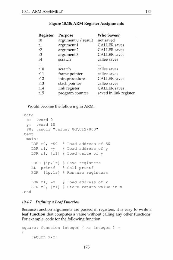
Figure 10.10: ARM Register Assignments
Register Purpose Who Saves?
r0 argument 0 / result not savedr1 argument 1 CALLER savesr2 argument 2 CALLER savesr3 argument 3 CALLER savesr4 scratch callee saves... ... ...r10 scratch callee savesr11 frame pointer callee savesr12 intraprocedure CALLER savesr13 stack pointer callee savesr14 link register CALLER savesr15 program counter saved in link register
Would become the following in ARM:
.data
x: .word 0
y: .word 10
S0: .ascii "value: %d\012\000"
.text
main:
LDR r0, =S0 @ Load address of S0
LDR r1, =y @ Load address of y
LDR r1, [r1] @ Load value of y
PUSH {ip,lr} @ Save registers
BL printf @ Call printf
POP {ip,lr} @ Restore registers
LDR r1, =x @ Load address of x
STR r0, [r1] @ Store return value in x
.end
10.4.7 Defining a Leaf Function
Because function arguments are passed in registers, it is easy to write aleaf function that computes a value without calling any other functions.For example, code for the following function:
square: function integer ( x: integer ) =
{
return x*x;
175

176 CHAPTER 10. ASSEMBLY LANGUAGE
}
Could be as simple as this:
.global square
square:
MUL r0, r0, r0 @ multiply argument by itself
BX lr @ return to caller
Unfortunately, this won’t work for a function that wants to invokeother functions, because we haven’t set up the stack properly. A morecomplex approach is needed for the general case.
10.4.8 Defining a Complex Function
A complex function must be able to invoke other functions and computeexpressions of arbitrary complexity, and then return to the caller with theoriginal state intact. Consider the following recipe for a function that ac-cepts three arguments and uses two local variables:
func:
PUSH {fp} @ save the frame pointer
MOV fp, sp @ set the new frame pointer
PUSH {r0,r1,r2} @ save the arguments on the stack
SUB sp, sp, #8 @ allocate two more local variables
PUSH {r4-r10} @ save callee-saved registers
@@@ body of function goes here @@@
POP {r4-r10} @ restore callee saved registers
MOV sp, fp @ reset stack pointer
POP {fp} @ recover previous frame pointer
BX lr @ return to the caller
Through this method, we ensure that we are able to save all the valuesin the registers into the stack and ensure that no data will be lost. Thestack, once this has been done, looks very similar to that of the X86 stack,just with some extra callee-saved registers stored on the stack.
Here is a complete example that puts it all together. Suppose that youhave a B-minor function defined as follows:
compute: function integer
( a: integer, b: integer, c: integer ) =
{
x: integer = a+b+c;
y: integer = x*5;
return y;
}
176
10.4. ARM ASSEMBLY 177
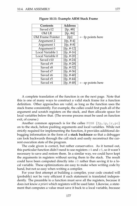
Figure 10.11: Example ARM Stack Frame
Contents AddressSaved r12 [fp, #8]
Old LR [fp, #4]Old Frame Pointer [fp] ← fp points here
Argument 2 [fp, #-4]Argument 1 [fp, #-8]Argument 0 [fp, #-12]
Local Variable 1 [fp, #-16]Local Variable 0 [fp, #-20]
Saved r10 [fp, #-24]Saved r9 [fp, #-28]Saved r8 [fp, #-32]Saved r7 [fp, #-36]Saved r6 [fp, #-40]Saved r5 [fp, #-44]Saved r4 [fp, #-48] ← sp points here
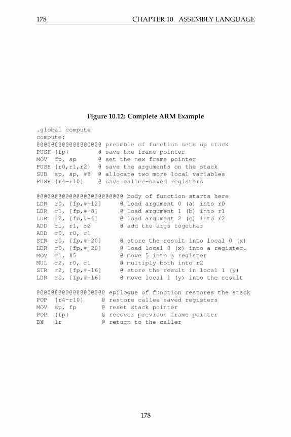
A complete translation of the function is on the next page. Note thatthis is one of many ways to construct a valid stack frame for a functiondefinition. Other approaches are valid, as long as the function uses thestack frame consistently. For example, the callee could first push all of theargument and scratch registers on the stack, and then allocate space forlocal variables below that. (The reverse process must be used on functionexit, of course.)
Another common approach is for the callee PUSH {fp,ip,lr,pc}on to the stack, before pushing arguments and local variables. While notstrictly required for implementing the function, it provides additional de-bugging information in the form of a stack backtrace so that a debuggercan look backwards through the call stack and easily reconstruct the cur-rent execution state of the program.
The code given is correct, but rather conservative. As it turned out,this particular function didn’t need to use registers r4 and r5, so it wasn’tnecessary to save and restore them. In a similar way, we could have keptthe arguments in registers without saving them to the stack. The resultcould have been computed directly into r0 rather than saving it to a lo-cal variable. These optimizations are easy to make when writing code byhand, but not so easy when writing a compiler.
For your first attempt at building a compiler, your code created will(probably) not be very efficient if each statement is translated indepen-dently. The preamble to a function must save all the registers, because itdoes not know a priori which registers will be used later. Likewise, a state-ment that computes a value must save it back to a local variable, because
177
178 CHAPTER 10. ASSEMBLY LANGUAGE
Figure 10.12: Complete ARM Example
.global compute
compute:
@@@@@@@@@@@@@@@@@@ preamble of function sets up stack
PUSH {fp} @ save the frame pointer
MOV fp, sp @ set the new frame pointer
PUSH {r0,r1,r2} @ save the arguments on the stack
SUB sp, sp, #8 @ allocate two more local variables
PUSH {r4-r10} @ save callee-saved registers
@@@@@@@@@@@@@@@@@@@@@@@@ body of function starts here
LDR r0, [fp,#-12] @ load argument 0 (a) into r0
LDR r1, [fp,#-8] @ load argument 1 (b) into r1
LDR r2, [fp,#-4] @ load argument 2 (c) into r2
ADD r1, r1, r2 @ add the args together
ADD r0, r0, r1
STR r0, [fp,#-20] @ store the result into local 0 (x)
LDR r0, [fp,#-20] @ load local 0 (x) into a register.
MOV r1, #5 @ move 5 into a register
MUL r2, r0, r1 @ multiply both into r2
STR r2, [fp,#-16] @ store the result in local 1 (y)
LDR r0, [fp,#-16] @ move local 1 (y) into the result
@@@@@@@@@@@@@@@@@@@ epilogue of function restores the stack
POP {r4-r10} @ restore callee saved registers
MOV sp, fp @ reset stack pointer
POP {fp} @ recover previous frame pointer
BX lr @ return to the caller
178

10.4. ARM ASSEMBLY 179
it does not know beforehand whether the local will be used as a returnvalue. We will explore these issues later in Chapter 12 on optimization.
10.4.9 64-bit Differences
The 64-bit ARMv8-A architecture provides two execution modes: The A32mode supports the 32-bit instruction set described above, and the A64mode supports a new 64-bit execution model. This permits a 64-bit CPUwith a supporting operating system to execute a mix of 32-bit and 64-bitprograms simultaneously. Though not binary compatible with A32, theA64 model follows much of the same architectural principles, with a fewkey changes:
Word Size. A64 instructions are still a fixed size of 32 bits, however,registers and address computations are 64 bits.
Registers. A64 has 32 64-bit registers, named x0-x31. x0 is a dedi-cated zero register: when read, it always provides the value zero, whenwritten, there is no effect. x1-x15 are general purpose registers, x16 andx17 are for interprocess communication, x29 is the frame pointer, x30 isthe link register and x31 is the stack pointer. (The program counter is notdirectly accessible from user code.) Instead of using a data type suffix, a32-bit value may be indicated by naming a register as w#.
Instructions. A64 instructions are largely the same as A32, using thesame mnemonics, with a few differences. Conditional predicates are nolonger part of every instruction. Instead, all conditional codes must per-form an explicit CMP and then a conditional branch. The LDM/STM in-structions and pseudo-instructions PUSH/POP are not available and mustbe replaced with a sequence of explicit loads and stores. (This can be mademore efficient by using LDP/STP which load and store pairs of registers.
Calling Convention. To invoke a function, the first eight argumentsare placed in registers x0-x7, and the remainder are pushed on to thestack. The caller must preserve registers x9-x15 and x30 while the calleemust preserve x19-x29. The (scalar) return value is placed in x0, whileextended return values are pointed to by x8.
179

180 CHAPTER 10. ASSEMBLY LANGUAGE
10.5 Further Reading
This chapter has given you a brief orientation to the core features of theX86 and ARM architectures, enough to write simple programs in the mostdirect way. However, you will certainly need to look up specific detailsof individual instructions in order to better understand their options andlimitations. Now you are ready to read the detailed reference manuals andkeep them handy while you construct your compiler:
1. Intel64 and IA-32 Architectures Software Developer Manuals. IntelCorp., 2017.http://www.intel.com/content/www/us/en/processors/architectures-software-developer-manuals.html
2. System V Application Binary Interface, Jan Hubicka, Andreas Jaeger,Michael Matz, and Mark Mitchell (editors), 2013. https://software.intel.com/sites/default/files/article/402129/mpx-linux64-abi.
3. ARM Architecture Reference Manual ARMv8. ARM Limited, 2017.https://static.docs.arm.com/ddi0487/bb/DDI0487B_b_armv8_
arm.pdf.
4. The ARM-THUMB Procedure Call Standard. ARM Limited, 2000.http://infocenter.arm.com/help/topic/com.arm.doc.espc0002/
ATPCS.pdf.
180