introduction to autocad 2012 - routledge · drawing from autocad 2012 is pasted into the microsoft...
TRANSCRIPT

Introduction to AutoCAD 2012Alf Yarwood
Chapter 10 Exercise 11. Open AutoCAD 2012 with a double-click on its shortcut icon in the Windows desktop.2. Open the template acadiso.dwt.3. Construct the drawing as shown using the Circle, Arc and Array tools
and save it as a wblock with the name Chapter10/fig01.dwg. Close thedrawing.
4. Open the acadiso.dwt template.5. Click External References... in the View/Palettes panel. The External
References palette appears. Click Attach DWG... in the popup list fromthe Attach DWG icon.
6. The Select Reference File dialog appears. Select Chapter10/Fig.01.dwg followed with a click on theOpen button.
7. The Attach External Reference dialog appears with the selected file name showing. Click the OK button.The command line shows:
Material accompanying Introduction to AutoCAD 2012, ISBN 9780080969473. Copyright © 2011, Alf Yarwood. Publishedby Elsevier Ltd. All rights reserved.
Page 1

Command: _XATTACHAttach Xref "Fig01": C:\Chapter10\inserts\Fig01.dwg"Fig01" loaded.Specify insertion point or [Scale/X/Y/Z/Rotate/PScale/PX/PY/PZ/PRotate]: pickRegenerating model.Command:
8. The drawing appears in the AutoCAD window.Remember it is an xref and is therefore a block.
9. Construct a Rectangular Array of the block in fourphases:
(a) In a single column of 4 rows spaced at -75.(b) Using the Copy tool, copy the original drawingto form the top of a second array, and again to formthe top of the right-hand array.(c) Construct the central array as a single columnof 5 rows spaced at -75.(d) Construct the right-hand array as a single columnof 4 rows spaced at -75.
10. Save the drawing - e.g. as Chapter10/Fig02.dwg.Close the drawing.
11. Open the drawing Fig01.dwg and, with the Erasetool, erase all hatching and rehatch with a differenthatch pattern.
12. Save the drawing to the same file name Fig01.dwg.13. Open the drawing Fig02.dwg containing the arrayed
xrefs. It will be seen that the drawings have changedto the new hatch pattern.
14. Save your drawing with the file name10_Exercise01.dwg to your memory stick.
15. Left-click the Close button of the drawing window.
Material accompanying Introduction to AutoCAD 2012, ISBN 9780080969473. Copyright © 2011, Alf Yarwood. Publishedby Elsevier Ltd. All rights reserved.
Page 2

Chapter 10 Exercise 21. Open AutoCAD 2012 with a double-click on its shortcut icon in the Windows desktop.2. Open the template acadiso.dwt.3. Construct the drawing as requested - showing the two ends in front view. Save to your memory stick to the
file name roller.dwg.
4. Close the drawing window and open the acadiso.dwt template and construct the drawing of the spindle. Saveto your memory stick to the file name assembly.dwg. Close the drawing.
5. Open roller.dwg and insert the drawing of the spindle (assembly.dwg) as an External Reference (xref)into position between the two ends of the drawing roller.dwg. Save the drawing to the same file nameroller.dwg.
6. Reopen the file assembly.dwg (of the spindle) and make changes as requested. Save the drawing to thesame file name - assembly.dwg.
Material accompanying Introduction to AutoCAD 2012, ISBN 9780080969473. Copyright © 2011, Alf Yarwood. Publishedby Elsevier Ltd. All rights reserved.
Page 3

7. Reopen roller.dwg and change in the outline of the spindle.8. Save your drawing with the file name 10_Exercise02.dwg to your memory stick.9. Left-click the Close button of the drawing window.
Chapter 10 Exercise 31. Open AutoCAD 2012 with a double-click on its shortcut icon in the
Windows desktop.2. Open the template acadiso.dwt.3. Open the External References palette with a click on its icon in the
View/Palettes panel. Left-click Attach Image ... in the drop-down menuof the palette.
4. The Select Reference File dialog appears. Left-click the required folderin the Look in: field and from the list select the required file.
5. Left-click on the file name of the image (in this case Gaudi_window.jpg.)Its preview appears in the Preview area (if Preview has been clicked).
6. Left-click the Open button of the dialog and the Attach Image dialogappears showing the name of the selected file, together with a preview.Left-click the OK button of the dialog and the command line shows:
Command: _imageattachSpecify insertion point <0,0>: pick a suitable pointBase image size: Width: 137.345932, Height:51.819599,Millimetres (Note these sizes)Specify scale factor <1>: enter a scale thought suitable(remembering the Base Image Scale) followed by a right-clickCommand:
Material accompanying Introduction to AutoCAD 2012, ISBN 9780080969473. Copyright © 2011, Alf Yarwood. Publishedby Elsevier Ltd. All rights reserved.
Page 4

Material accompanying Introduction to AutoCAD 2012, ISBN 9780080969473. Copyright © 2011, Alf Yarwood. Publishedby Elsevier Ltd. All rights reserved.
Page 5
7. Insert several *.jpg images in this manner entering a different scale for each.8. Save your drawing with the file name 8_Exercise03.dwg to your memory stick.9. Left-click the Close button of the drawing window.
Chapter 10 Exercise 41. Open AutoCAD 2012 with a double-click on its shortcut icon in the Windows desktop.2. Open the first drawing of the array constructed when answering Exercise 1.3. Left-click the Copy Clip icon in the Home/Clipboards panel.
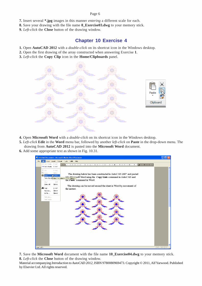
4. Open Microsoft Word with a double-click on its shortcut icon in the Windows desktop.5. Left-click Edit in the Word menu bar, followed by another left-click on Paste in the drop-down menu. The
drawing from AutoCAD 2012 is pasted into the Microsoft Word document.6. Add some appropriate text as shown in Fig. 10.31.
7. Save the Microsoft Word document with the file name 10_Exercise04.dwg to your memory stick.8. Left-click the Close button of the drawing window.Material accompanying Introduction to AutoCAD 2012, ISBN 9780080969473. Copyright © 2011, Alf Yarwood. Publishedby Elsevier Ltd. All rights reserved.
Page 6

Chapter 10 Exercise 5
1. Examine the drawings of Figs 10.1,10.2 and 10.3.
2. The upper drawing to the right showsthe plan view of these twoillustrations.
3. The lower drawing shows the correctplan view with the two sloping endsof the roof hatched.
.
Additional exercises1. Open four drawings which have been saved to file and using the Multiple Drawing Environment arrange
the four drawings in the manner shown in the illustration below.
Material accompanying Introduction to AutoCAD 2012, ISBN 9780080969473. Copyright © 2011, Alf Yarwood. Publishedby Elsevier Ltd. All rights reserved..
Page 7

2. The upper drawing shows a plan of a plate held inposition with six hexagonal headed bolts. The boltshave been added to the drawing of the plan of theplate as external references. By amending the Xrefdrawing of the bolt heads change the bolt heads asshown in the lower drawing. Sizes are left to your ownjudgement.
3. (a) Construct the left-hand drawing hatching it withany suitable hatch patterns. Save the drawing to asuitable file name.
( b) Place the drawing into an acadiso.dwt screen asan xref and array as shown in the larger drawingbelow. Save the drawing to a suitable file name.
(c) Open the original drawing and change the hatchpatterns as shown to the right of the upper drawing.Save the drawing to the same file name.
(d) Open the array drawing containing the xref andnote the changes.
Material accompanying Introduction to AutoCAD 2012, ISBN 9780080969473. Copyright © 2011, Alf Yarwood. Publishedby Elsevier Ltd. All rights reserved.
Page 8

4. Open any one of the drawings saved to file and using the Copy command from the Edit drop-down menu,Paste the drawing into a Word document. Add some text. An example is shown below.
Multiple choice questions1. When using one of the Paste tools from the Home/Clipboard panel, the drawing can be pasted into documents
being worked in other applications. The method of copying and pasting makes use of:(a) A DXF file(b) An EPS file(c) Any item in any application can be automatically copied into another application(d) The drawing is transferred via the Clipboard.
2. When a drawing is saved as an EPS file and the EPS file is inserted into a document being worked in anotherapplication:
(a) Changes made in the AutoCAD drawing will be automatically updated in the drawing in the otherapplication(b) Changes made in the AutoCAD drawing are not reflected in the document into which the drawing hasbeen inserted(c) Changes made in the AutoCAD drawing are only changed in the inserted drawing after both the drawingand the document have been saved to file(d) It does not matter whether the drawing is changed or not, no changes will be reflected in the otherdocument.
3. The reason for saving an AutoCAD drawing as an DXF file is:(a) The DXF file can be opened in any other Computer Aided Design (CAD) application(b) DXF files take up less space on a file than the AutoCAD DWG file(c) DXF files can be opened in a Microsoft Word document(d) DXF files can be opened in earlier releases of AutoCAD.
4. External references (xrefs) can be described as:(a) They are the same as blocks and are saved within the drawing file in which they were constructed, butcan be inserted into other drawings(b) They are different to blocks in that changes in an original external reference are reflected in thedrawing in which the xref is inserted(c) They are blocks which are saved to file names in their own right(d) They are files which refer to parts within a drawing.
Material accompanying Introduction to AutoCAD 2012, ISBN 9780080969473. Copyright © 2011, Alf Yarwood. Publishedby Elsevier Ltd. All rights reserved.
Page 9

Page 10
5. Which files with the following file name extensions are “raster” files?(a) *.bmp(b) *.dwg(c) *.tif(d). *.dxf(e). *.jpg(f). *.eps(g) *.pcx.
Material accompanying Introduction to AutoCAD 2012, ISBN 9780080969473. Copyright © 2011, Alf Yarwood. Publishedby Elsevier Ltd. All rights reserved.