introduction to assembly language programming …portal.unimap.edu.my/portal/page/portal30/lecturer...
TRANSCRIPT
Introduction to Assembly
Language Programming
1/18/2011 1
Language Programming
(Instruction Set)
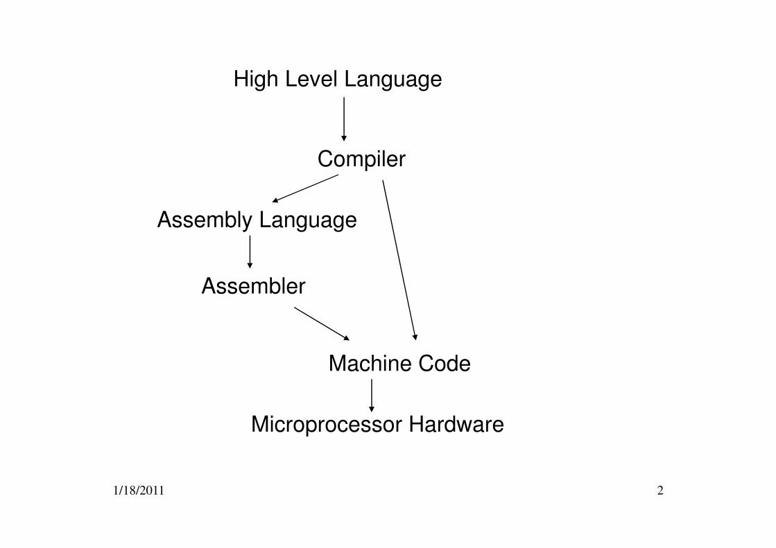
High Level Language
Compiler
Assembly Language
Assembler
1/18/2011 2
Assembler
Machine Code
Microprocessor Hardware
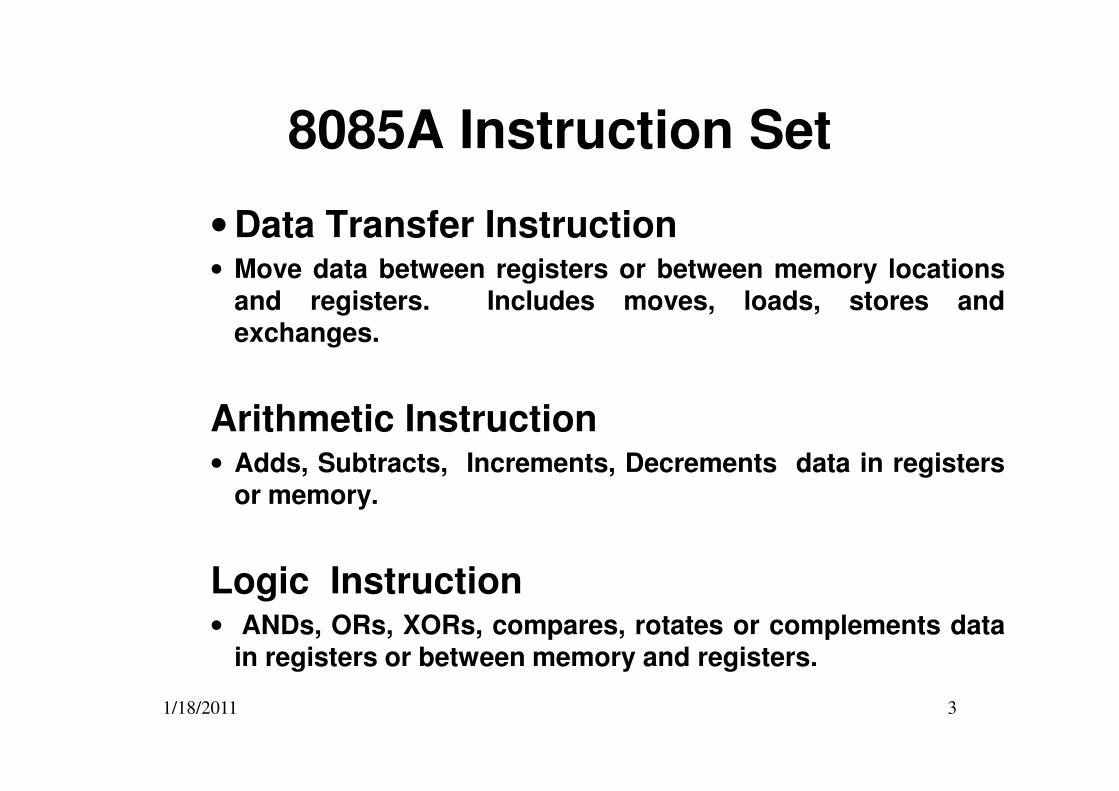
8085A Instruction Set
• Data Transfer Instruction• Move data between registers or between memory locations
and registers. Includes moves, loads, stores andexchanges.
1/18/2011 3
Arithmetic Instruction• Adds, Subtracts, Increments, Decrements data in registers
or memory.
Logic Instruction• ANDs, ORs, XORs, compares, rotates or complements data
in registers or between memory and registers.
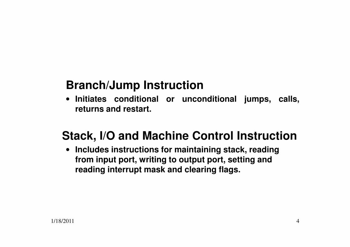
Branch/Jump Instruction• Initiates conditional or unconditional jumps, calls,
returns and restart.
1/18/2011 4
Stack, I/O and Machine Control Instruction• Includes instructions for maintaining stack, reading
from input port, writing to output port, setting and reading interrupt mask and clearing flags.
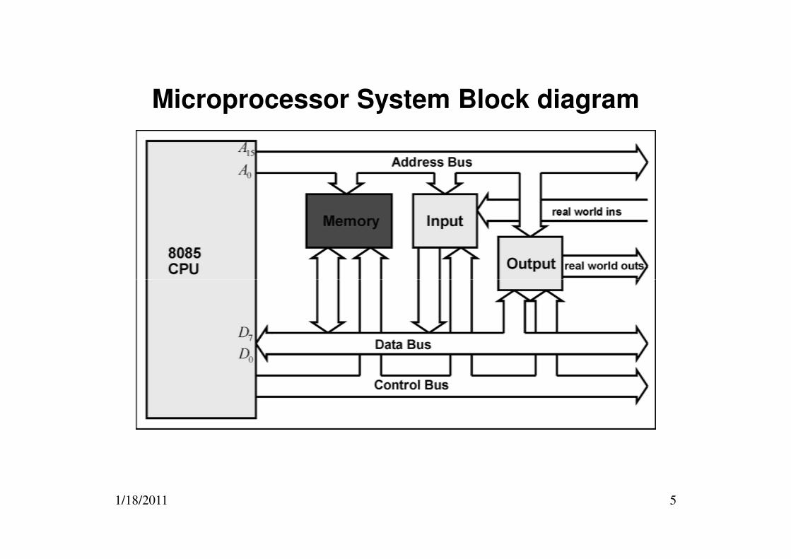
Microprocessor System Block diagram
1/18/2011 5
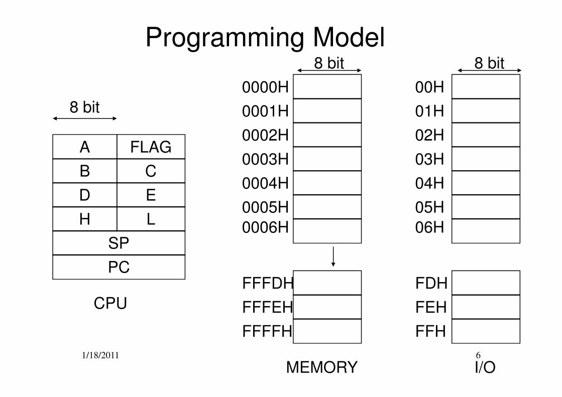
Programming Model
0000H
0003H
0001H
0002H
0005H
0004H
A
B
D E
C
FLAG
8 bit
8 bit
00H
03H
01H
02H
05H
04H
8 bit
1/18/2011 6
0005H
FFFDH
0006H
FFFFH
FFFEH
MEMORY
D E
H L
SP
PC
CPU
05H
FDH
06H
FFH
FEH
I/O
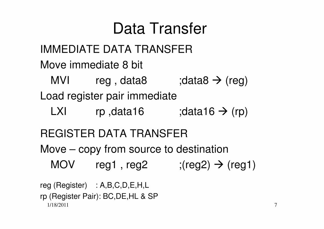
Data Transfer
IMMEDIATE DATA TRANSFER
Move immediate 8 bit
MVI reg , data8 ;data8 � (reg)
Load register pair immediate
LXI rp ,data16 ;data16 � (rp)
1/18/2011 7
LXI rp ,data16 ;data16 � (rp)
REGISTER DATA TRANSFER
Move – copy from source to destination
MOV reg1 , reg2 ;(reg2) � (reg1)
reg (Register) : A,B,C,D,E,H,L
rp (Register Pair): BC,DE,HL & SP
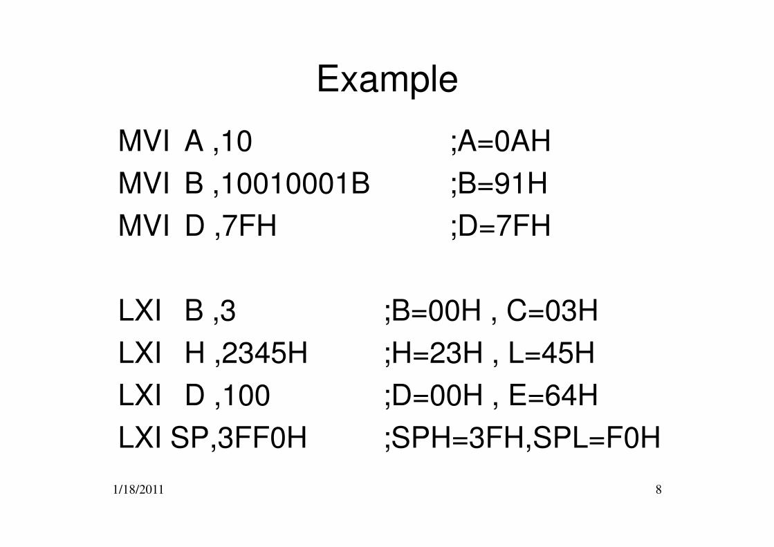
Example
MVI A ,10 ;A=0AH
MVI B ,10010001B ;B=91H
MVI D ,7FH ;D=7FH
1/18/2011 8
LXI B ,3 ;B=00H , C=03H
LXI H ,2345H ;H=23H , L=45H
LXI D ,100 ;D=00H , E=64H
LXI SP,3FF0H ;SPH=3FH,SPL=F0H
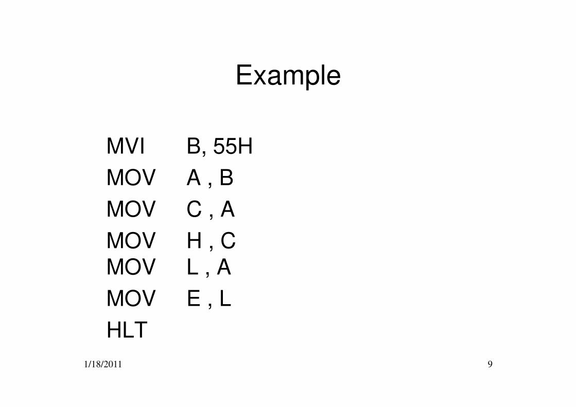
Example
MVI B, 55H
MOV A , B
MOV C , A
1/18/2011 9
MOV C , A
MOV H , CMOV L , A
MOV E , L
HLT
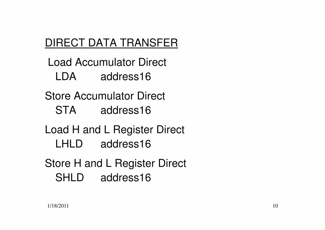
DIRECT DATA TRANSFER
Load Accumulator Direct
LDA address16
Store Accumulator Direct
STA address16
1/18/2011 10
STA address16
Load H and L Register Direct
LHLD address16
Store H and L Register Direct
SHLD address16
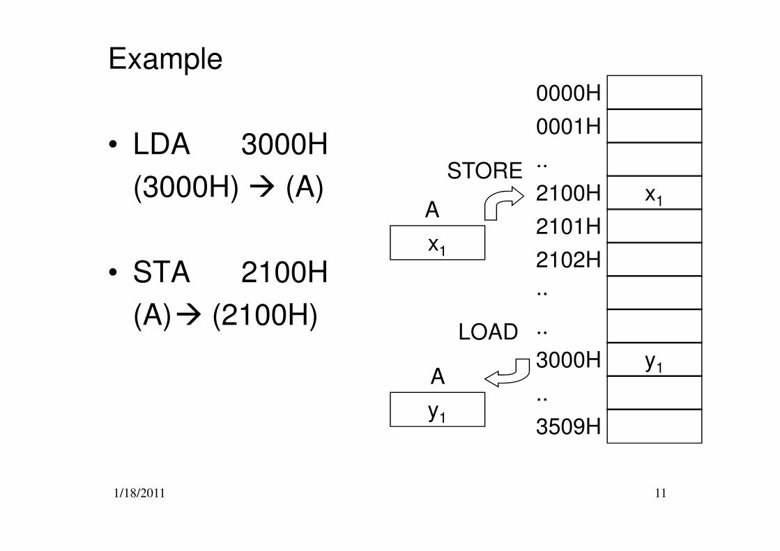
Example
• LDA 3000H
(3000H) � (A)
• STA 2100H
x1
0000H
2100H
0001H
..
2102H
2101H
..
A
x1
STORE
1/18/2011 11
• STA 2100H
(A)� (2100H)
3000H
..
3509H
y1
..
..A
y1
LOAD
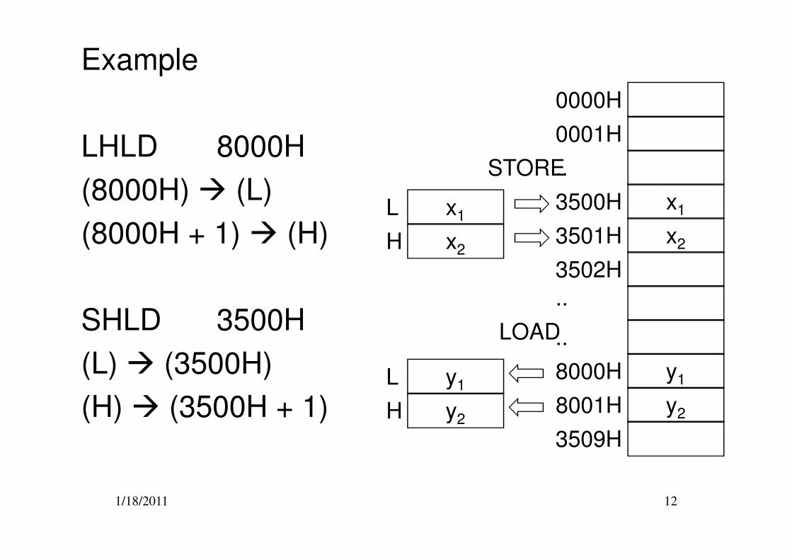
Example
LHLD 8000H
(8000H) � (L)
(8000H + 1) � (H)x1
0000H
3500H
0001H
..
3502H
3501HH
x1
STORE
x2x2
L
1/18/2011 12
SHLD 3500H
(L) � (3500H)
(H) � (3500H + 1) y2
3502H
8000H
..
3509H
y1
..
8001H
L y1
LOAD
y2H
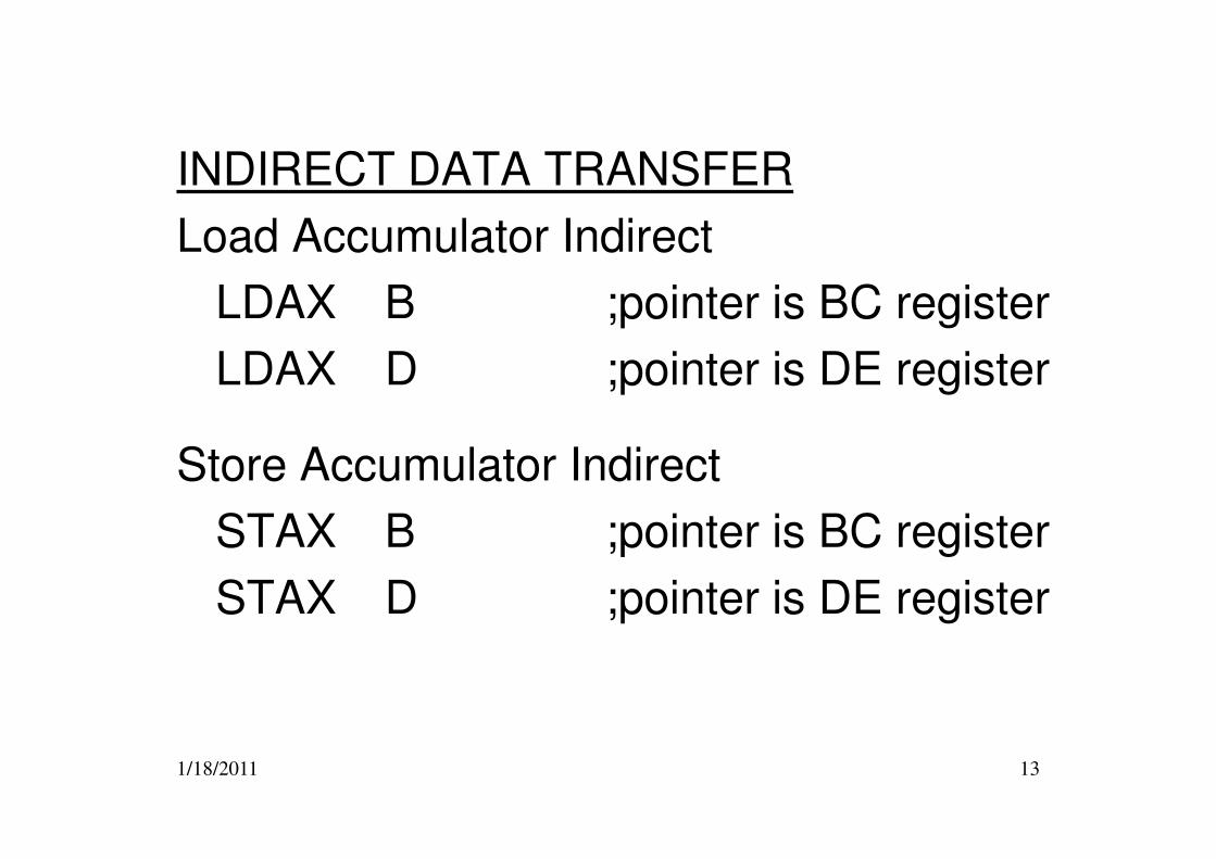
INDIRECT DATA TRANSFER
Load Accumulator Indirect
LDAX B ;pointer is BC register
LDAX D ;pointer is DE register
1/18/2011 13
Store Accumulator Indirect
STAX B ;pointer is BC register
STAX D ;pointer is DE register
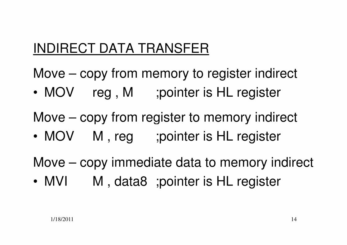
INDIRECT DATA TRANSFER
Move – copy from memory to register indirect
• MOV reg , M ;pointer is HL register
Move – copy from register to memory indirect
1/18/2011 14
Move – copy from register to memory indirect
• MOV M , reg ;pointer is HL register
Move – copy immediate data to memory indirect
• MVI M , data8 ;pointer is HL register

Example
ORG 0000H
LXI B , 2020H
MVI A , 88H
STAX B
INX B
LDAX B
LXI H , 3000H
0000H
0003H
0001H
0002H
0005H
0004H
0006H
1/18/2011 15
LXI H , 3000H
MOV D , M
MOV M , A88H
AAH
2020H
0006H
3000H
B
D
88H
00H30H
20H 20HA
H L
C2021H
FFH
0000H
0003H
0001H
0002H
0005H
0004H
0006H
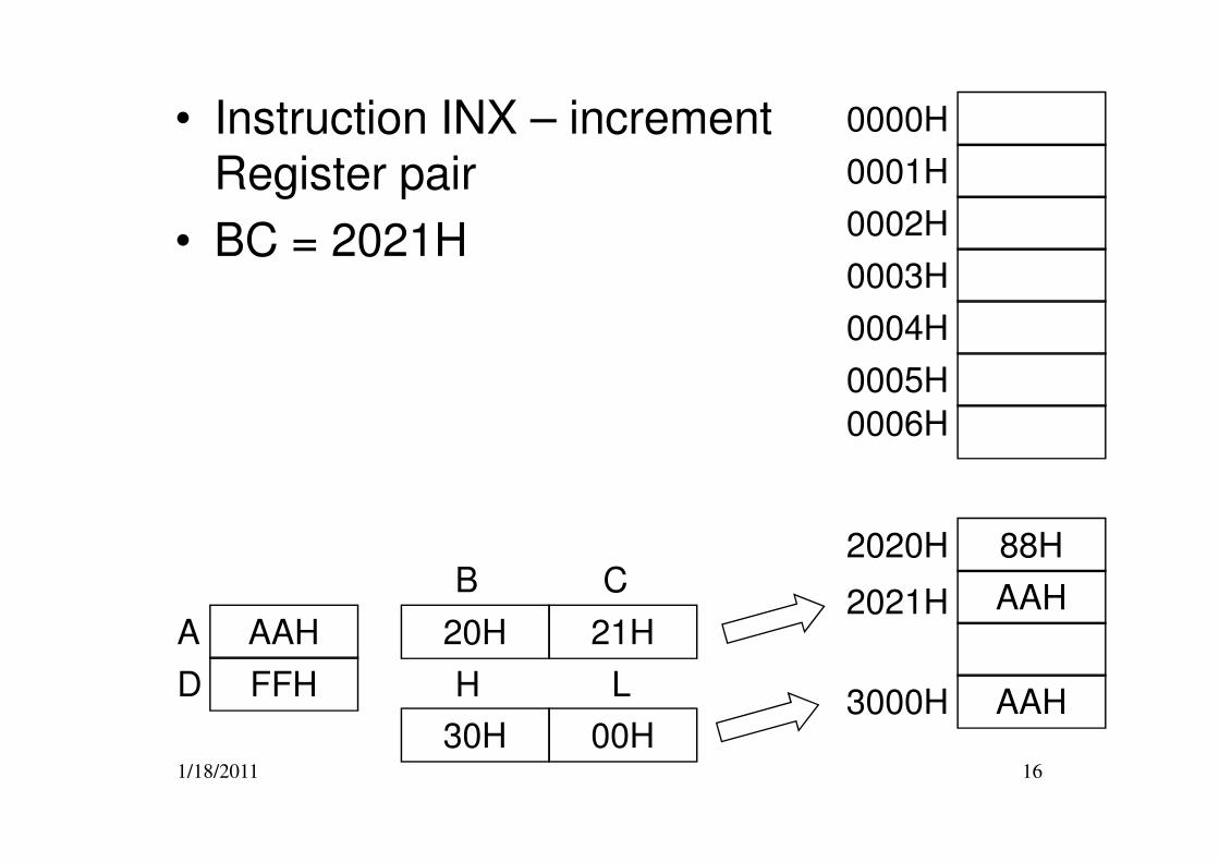
• Instruction INX – increment Register pair
• BC = 2021H
1/18/2011 16
88H
AAH
2020H
0006H
3000H
B
D
AAH
00H30H
FFH
20H 21HA
H L
C2021H
AAH
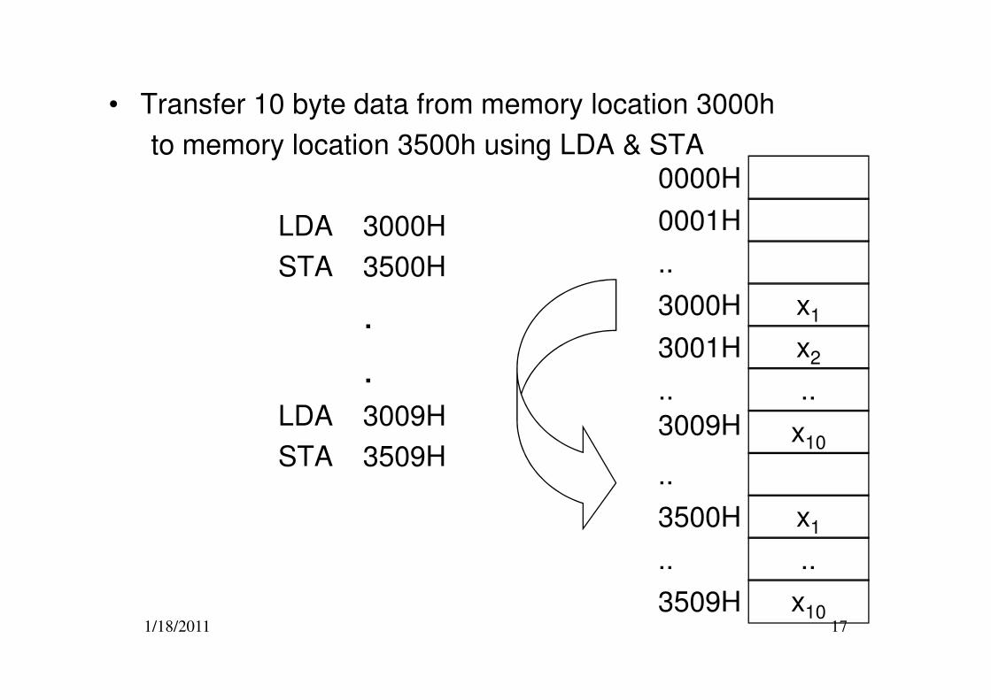
• Transfer 10 byte data from memory location 3000h
to memory location 3500h using LDA & STA
LDA 3000H
STA 3500H
.
.
x1
x2
0000H
3000H
0001H
..
3001H
1/18/2011 17
.LDA 3009H
STA 3509H
x2
..
x10
..
..
3001H
3500H
3009H
3509H
x1
x10
..
..
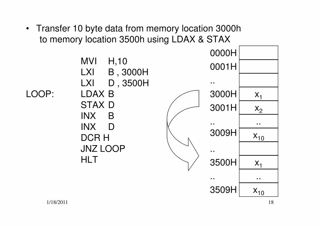
• Transfer 10 byte data from memory location 3000h
to memory location 3500h using LDAX & STAX
MVI H,10
LXI B , 3000H
LXI D , 3500H
LOOP: LDAX B
STAX D
INX B
x1
x2
0000H
3000H
0001H
..
3001H
1/18/2011 18
INX B
INX D
DCR H
JNZ LOOP
HLT
..
x10
..
..
3500H
3009H
3509H
x1
x10
..
..
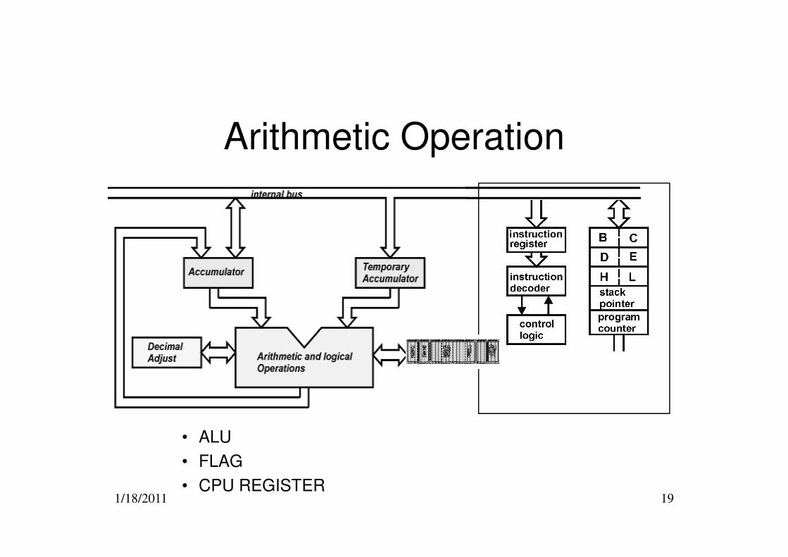
Arithmetic Operation
1/18/2011 19
• ALU
• FLAG
• CPU REGISTER
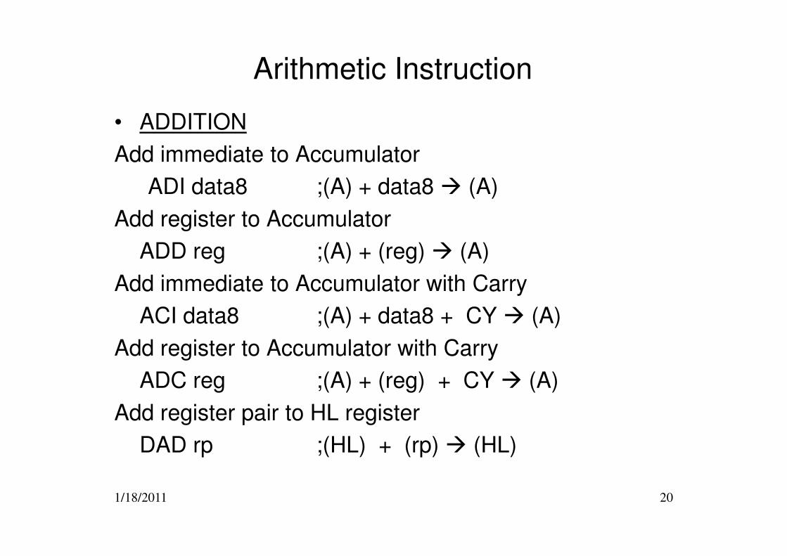
Arithmetic Instruction
• ADDITION
Add immediate to Accumulator
ADI data8 ;(A) + data8 � (A)
Add register to Accumulator
ADD reg ;(A) + (reg) � (A)
Add immediate to Accumulator with Carry
1/18/2011 20
Add immediate to Accumulator with Carry
ACI data8 ;(A) + data8 + CY � (A)
Add register to Accumulator with Carry
ADC reg ;(A) + (reg) + CY � (A)
Add register pair to HL register
DAD rp ;(HL) + (rp) � (HL)
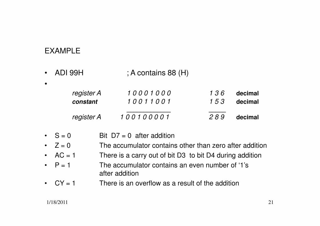
EXAMPLE
• ADI 99H ; A contains 88 (H)
•register A 1 0 0 0 1 0 0 0 1 3 6 decimal
constant 1 0 0 1 1 0 0 1 1 5 3 decimal
_____________ _____
1/18/2011 21
register A 1 0 0 1 0 0 0 0 1 2 8 9 decimal
• S = 0 Bit D7 = 0 after addition
• Z = 0 The accumulator contains other than zero after addition
• AC = 1 There is a carry out of bit D3 to bit D4 during addition
• P = 1 The accumulator contains an even number of ‘1’s
after addition
• CY = 1 There is an overflow as a result of the addition
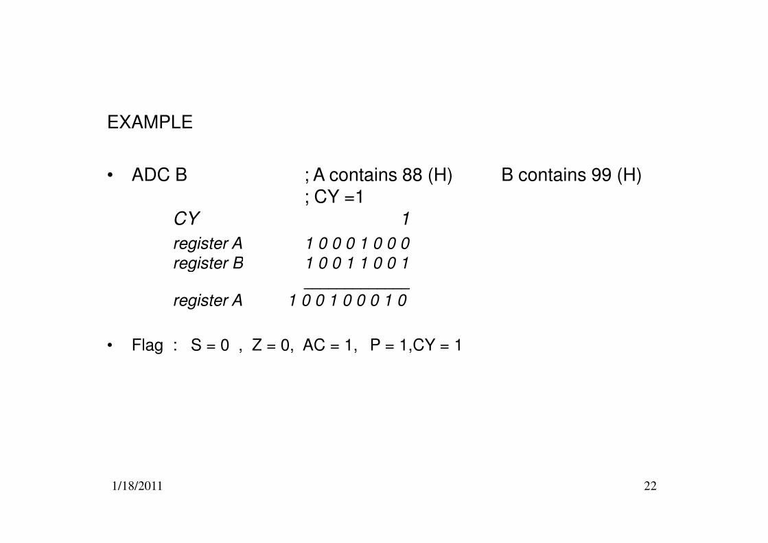
EXAMPLE
• ADC B ; A contains 88 (H) B contains 99 (H); CY =1
CY 1
register A 1 0 0 0 1 0 0 0
register B 1 0 0 1 1 0 0 1
1/18/2011 22
register B 1 0 0 1 1 0 0 1_____________
register A 1 0 0 1 0 0 0 1 0
• Flag : S = 0 , Z = 0, AC = 1, P = 1,CY = 1
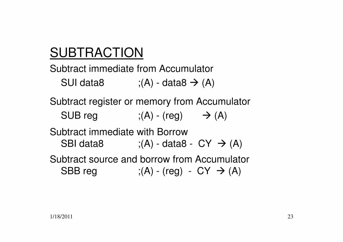
SUBTRACTIONSubtract immediate from Accumulator
SUI data8 ;(A) - data8 � (A)
Subtract register or memory from Accumulator
SUB reg ;(A) - (reg) � (A)
1/18/2011 23
Subtract immediate with Borrow SBI data8 ;(A) - data8 - CY � (A)
Subtract source and borrow from Accumulator SBB reg ;(A) - (reg) - CY � (A)
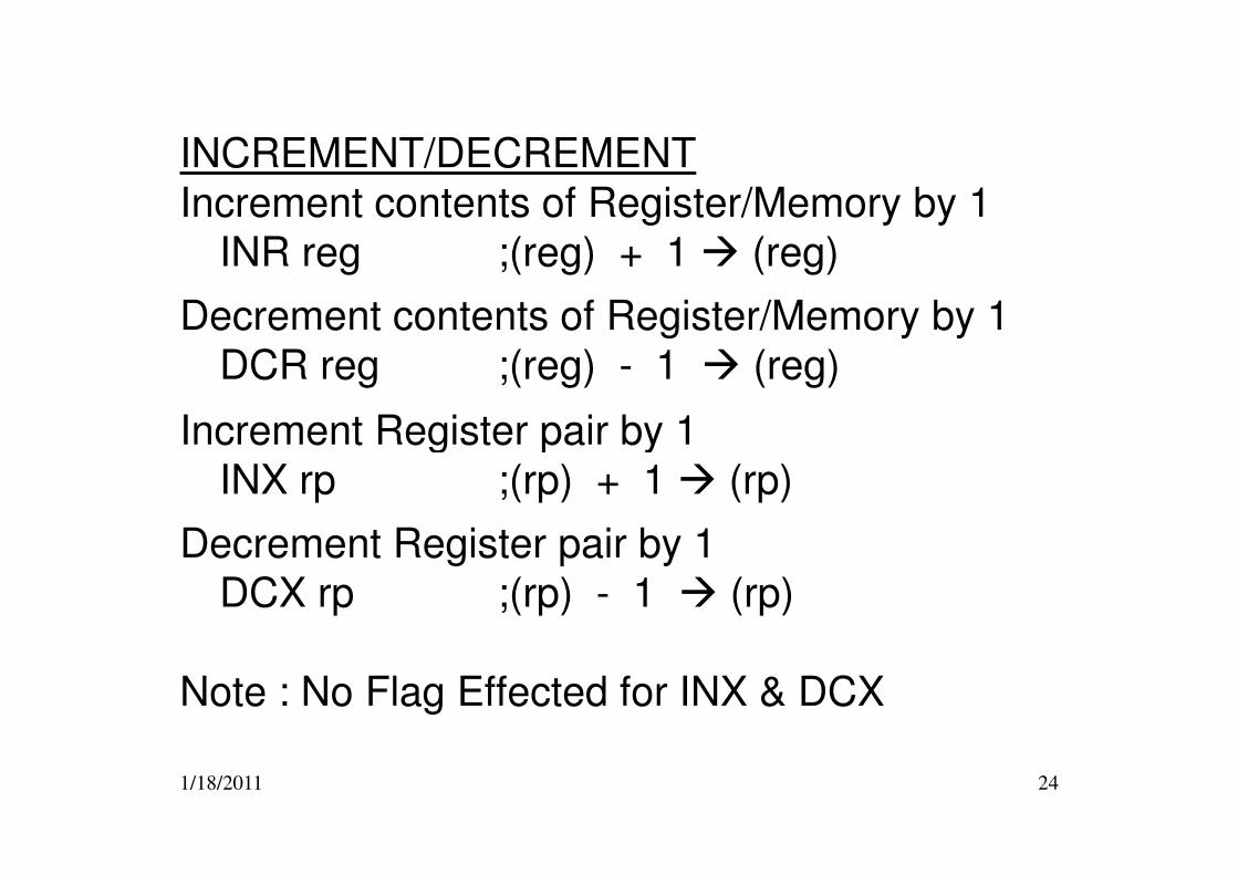
INCREMENT/DECREMENT
Increment contents of Register/Memory by 1
INR reg ;(reg) + 1 � (reg)
Decrement contents of Register/Memory by 1
DCR reg ;(reg) - 1 � (reg)
Increment Register pair by 1
1/18/2011 24
Increment Register pair by 1
INX rp ;(rp) + 1 � (rp)
Decrement Register pair by 1
DCX rp ;(rp) - 1 � (rp)
Note : No Flag Effected for INX & DCX
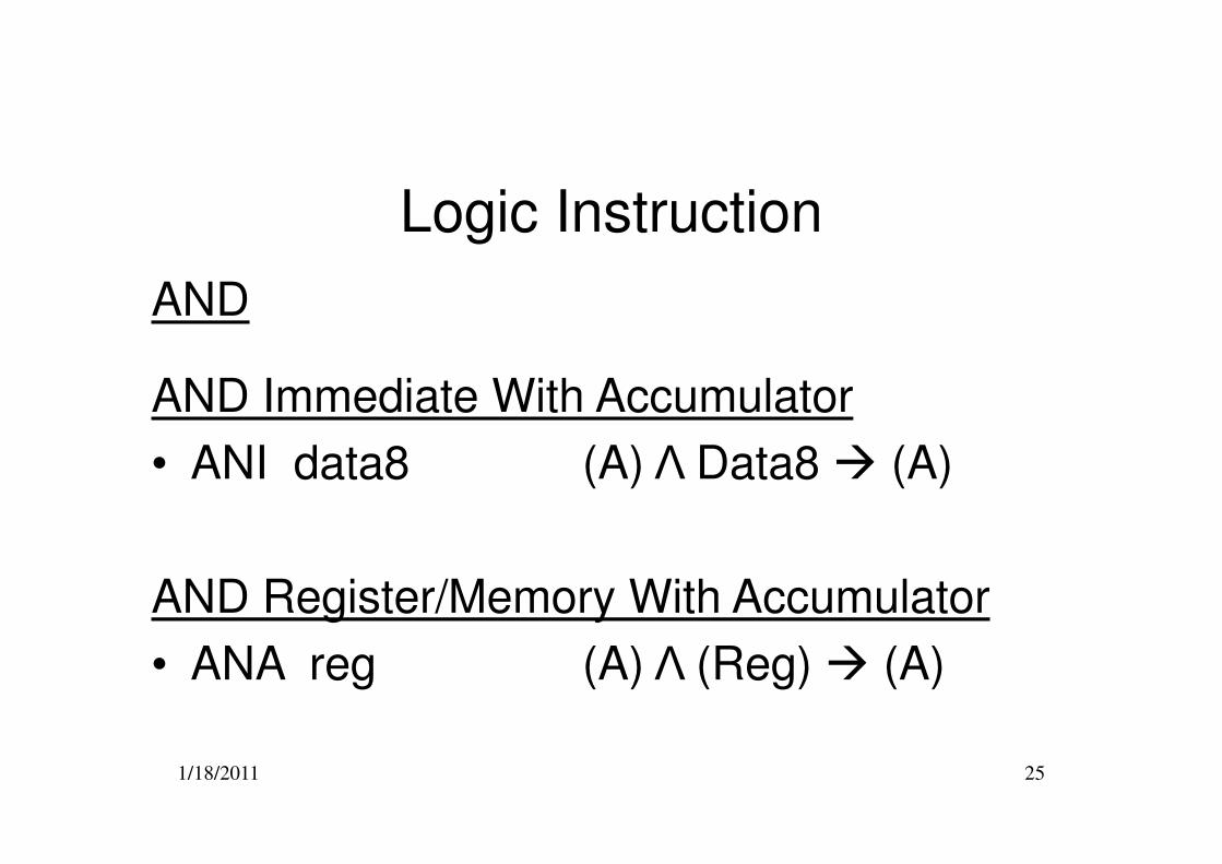
Logic Instruction
AND
AND Immediate With Accumulator
1/18/2011 25
• ANI data8 (A) Λ Data8 � (A)
AND Register/Memory With Accumulator
• ANA reg (A) Λ (Reg) � (A)
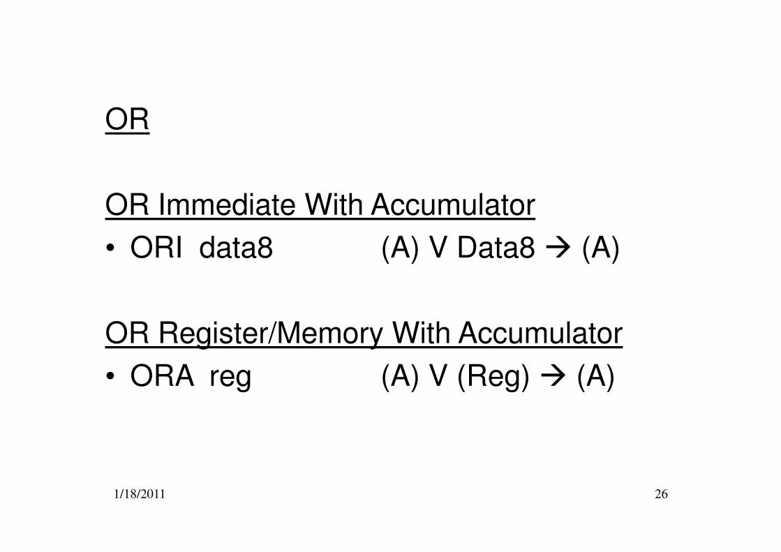
OR
OR Immediate With Accumulator
• ORI data8 (A) V Data8 � (A)
1/18/2011 26
OR Register/Memory With Accumulator
• ORA reg (A) V (Reg) � (A)
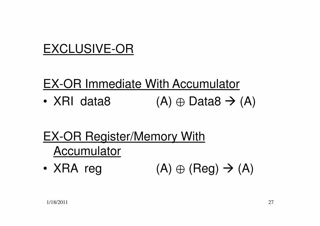
EXCLUSIVE-OR
EX-OR Immediate With Accumulator
• XRI data8 (A) ⊕ Data8 � (A)
1/18/2011 27
EX-OR Register/Memory With Accumulator
• XRA reg (A) ⊕ (Reg) � (A)
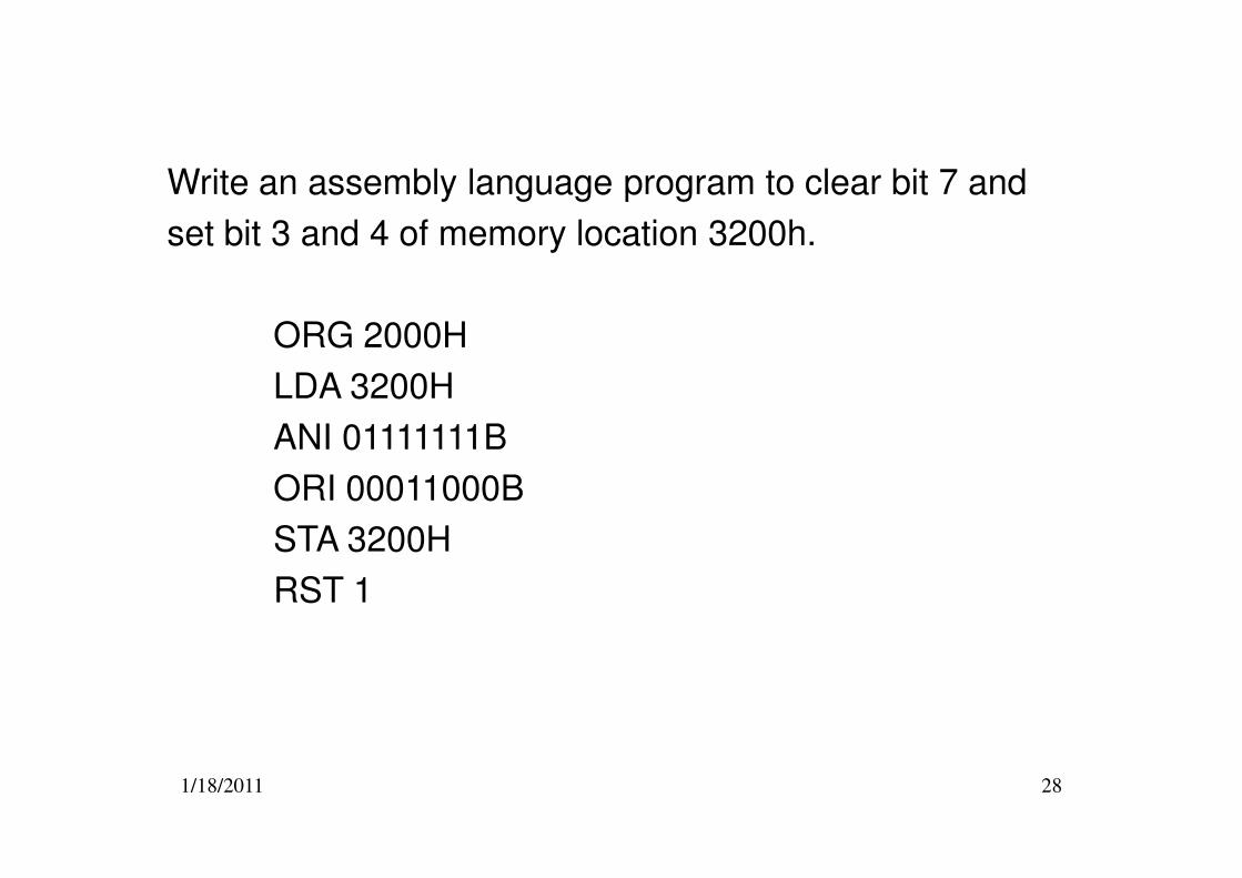
Write an assembly language program to clear bit 7 and
set bit 3 and 4 of memory location 3200h.
ORG 2000H
LDA 3200H
ANI 01111111B
1/18/2011 28
ANI 01111111B
ORI 00011000B
STA 3200H
RST 1
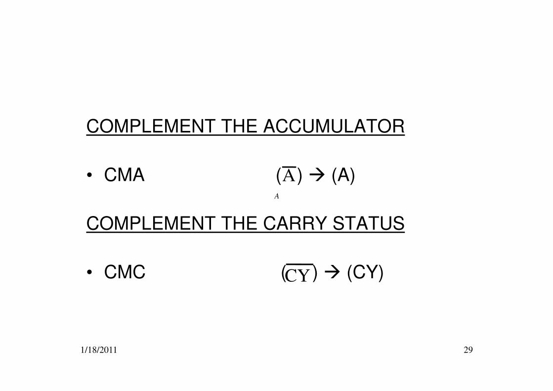
COMPLEMENT THE ACCUMULATOR
• CMA ( ) � (A)A
A
1/18/2011 29
COMPLEMENT THE CARRY STATUS
• CMC ( ) � (CY)
A
CY
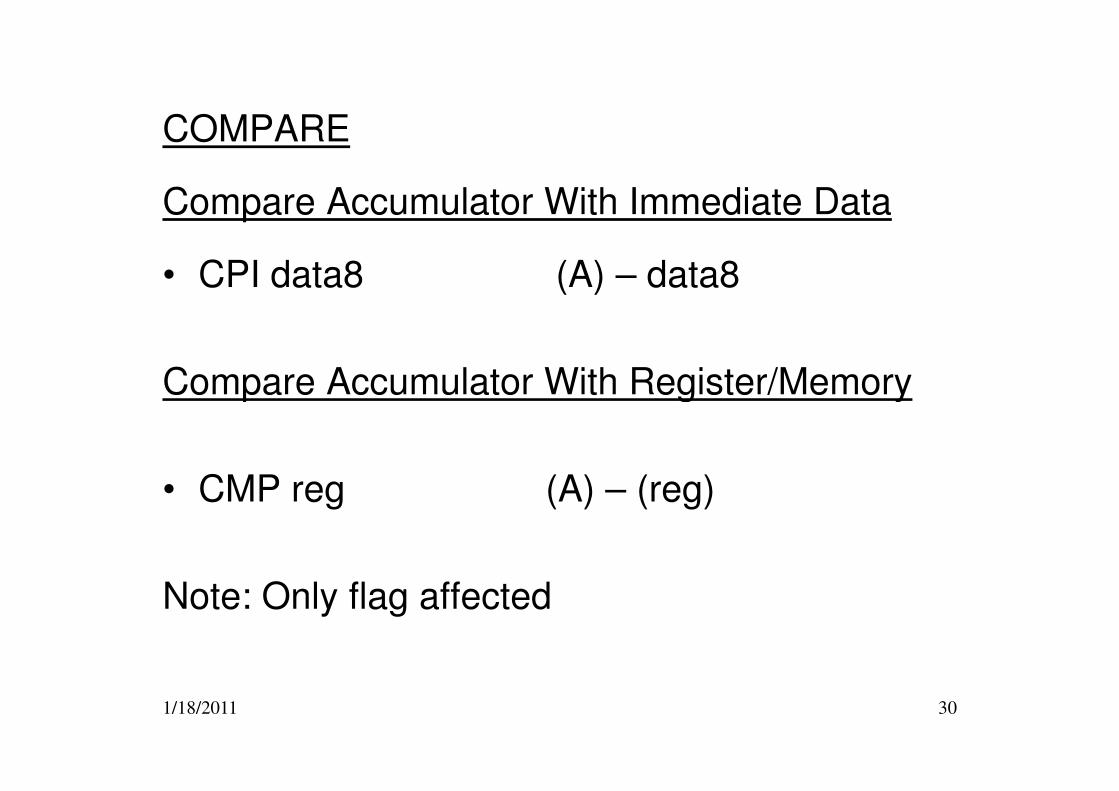
COMPARE
Compare Accumulator With Immediate Data
• CPI data8 (A) – data8
Compare Accumulator With Register/Memory
1/18/2011 30
Compare Accumulator With Register/Memory
• CMP reg (A) – (reg)
Note: Only flag affected
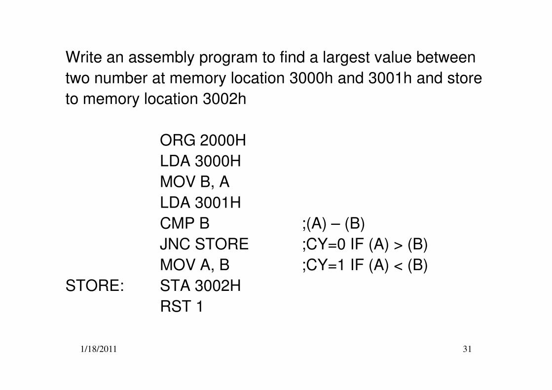
Write an assembly program to find a largest value between
two number at memory location 3000h and 3001h and store
to memory location 3002h
ORG 2000H
LDA 3000H
MOV B, A
LDA 3001H
1/18/2011 31
LDA 3001H
CMP B ;(A) – (B)
JNC STORE ;CY=0 IF (A) > (B)
MOV A, B ;CY=1 IF (A) < (B)
STORE: STA 3002H
RST 1
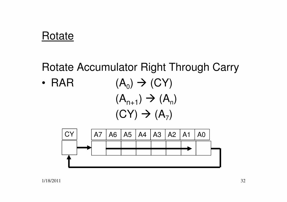
Rotate
Rotate Accumulator Right Through Carry
• RAR (A0) � (CY)
(An+1) � (An)
1/18/2011 32
(An+1) � (An)
(CY) � (A7)
A0A1A2A3A4A5A6A7CY
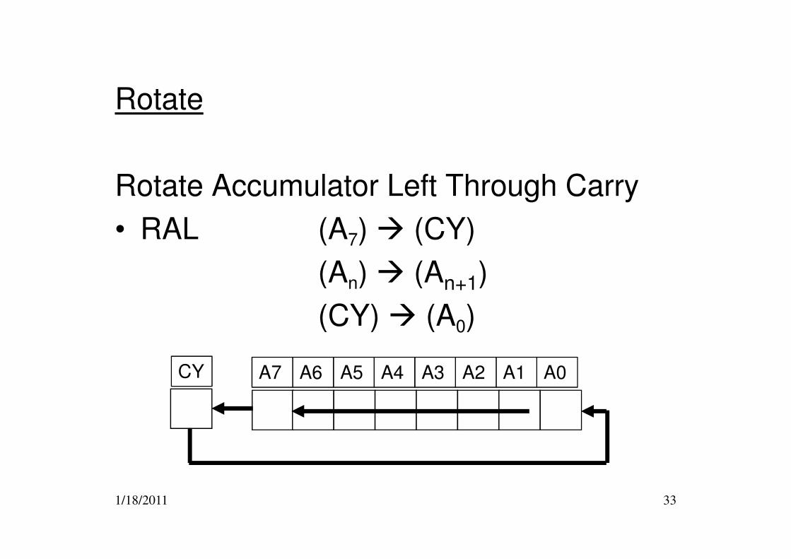
Rotate
Rotate Accumulator Left Through Carry
• RAL (A7) � (CY)
(An) � (An+1)
1/18/2011 33
(An) � (An+1)
(CY) � (A0)
A0A1A2A3A4A5A6A7CY
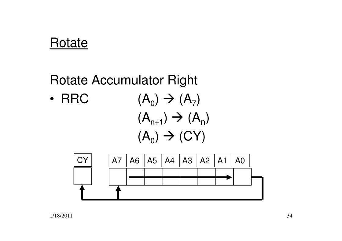
Rotate
Rotate Accumulator Right
• RRC (A0) � (A7)
(An+1) � (An)
1/18/2011 34
(An+1) � (An)
(A0) � (CY)
A0A1A2A3A4A5A6A7CY
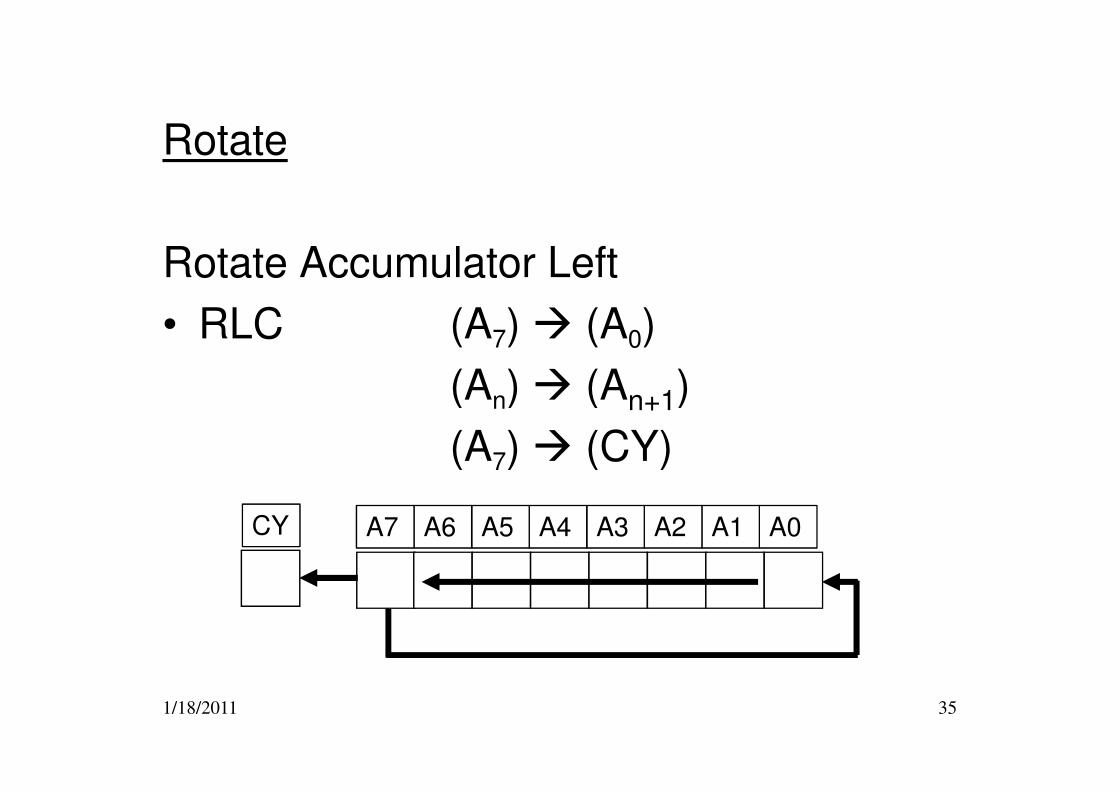
Rotate
Rotate Accumulator Left
• RLC (A7) � (A0)
(An) � (An+1)
1/18/2011 35
(An) � (An+1)
(A7) � (CY)
A0A1A2A3A4A5A6A7CY
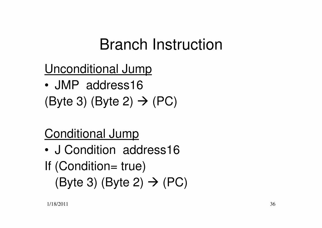
Branch Instruction
Unconditional Jump
• JMP address16
(Byte 3) (Byte 2) � (PC)
1/18/2011 36
Conditional Jump
• J Condition address16
If (Condition= true)
(Byte 3) (Byte 2) � (PC)
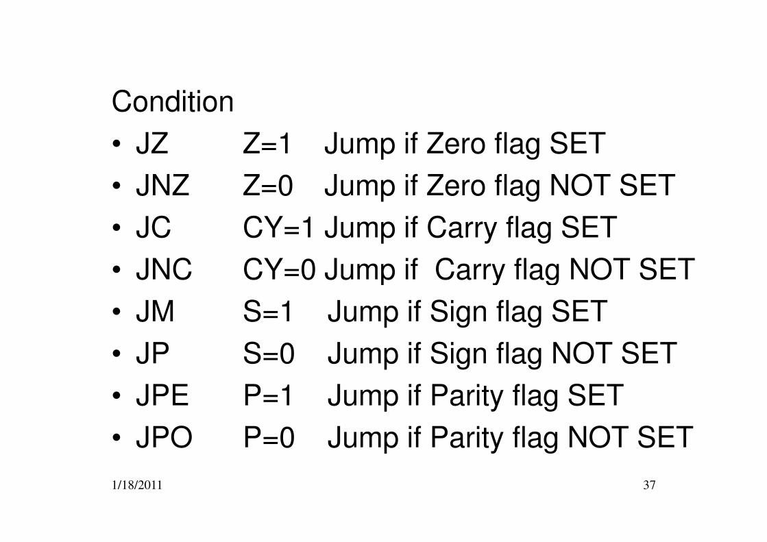
Condition
• JZ Z=1 Jump if Zero flag SET
• JNZ Z=0 Jump if Zero flag NOT SET
• JC CY=1 Jump if Carry flag SET
• JNC CY=0 Jump if Carry flag NOT SET
1/18/2011 37
• JNC CY=0 Jump if Carry flag NOT SET
• JM S=1 Jump if Sign flag SET
• JP S=0 Jump if Sign flag NOT SET
• JPE P=1 Jump if Parity flag SET
• JPO P=0 Jump if Parity flag NOT SET
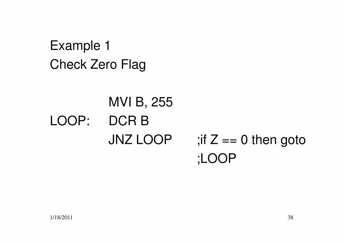
Example 1
Check Zero Flag
MVI B, 255
LOOP: DCR B
1/18/2011 38
LOOP: DCR B
JNZ LOOP ;if Z == 0 then goto
;LOOP
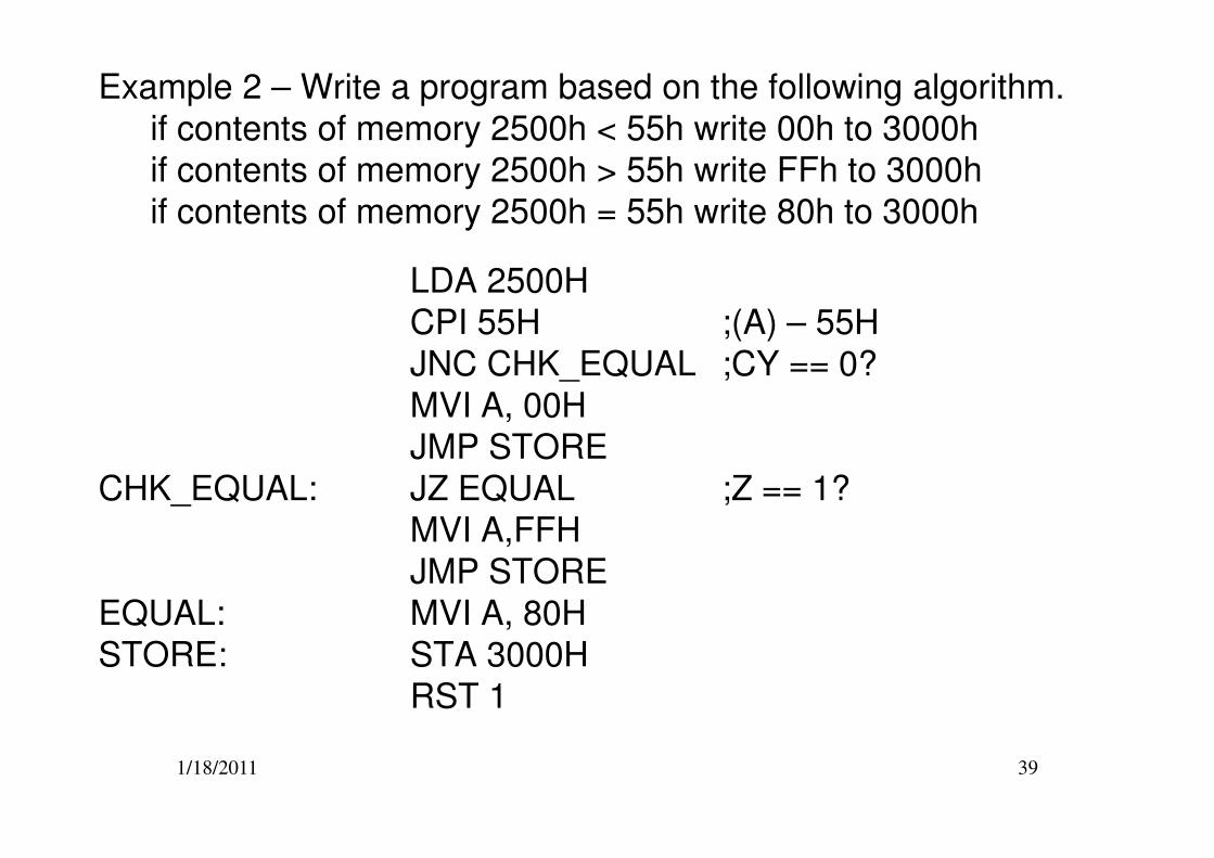
Example 2 – Write a program based on the following algorithm.
if contents of memory 2500h < 55h write 00h to 3000h
if contents of memory 2500h > 55h write FFh to 3000h
if contents of memory 2500h = 55h write 80h to 3000h
LDA 2500H
CPI 55H ;(A) – 55H
JNC CHK_EQUAL ;CY == 0?
MVI A, 00H
JMP STORE
1/18/2011 39
JMP STORE
CHK_EQUAL: JZ EQUAL ;Z == 1?
MVI A,FFH
JMP STORE
EQUAL: MVI A, 80H
STORE: STA 3000H
RST 1
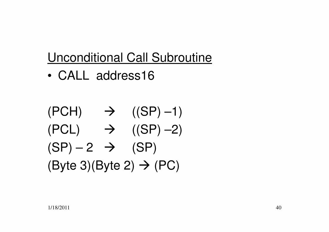
Unconditional Call Subroutine
• CALL address16
(PCH) � ((SP) –1)
1/18/2011 40
(PCH) � ((SP) –1)
(PCL) � ((SP) –2)
(SP) – 2 � (SP)
(Byte 3)(Byte 2) � (PC)
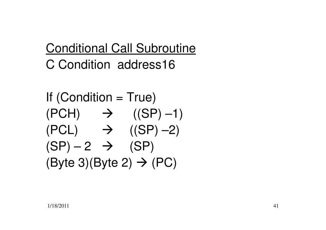
Conditional Call Subroutine
C Condition address16
If (Condition = True)
(PCH) � ((SP) –1)
1/18/2011 41
(PCH) � ((SP) –1)
(PCL) � ((SP) –2)
(SP) – 2 � (SP)
(Byte 3)(Byte 2) � (PC)

• CZ Z=1 Call if Zero flag SET
• CNZ Z=0 Call if Zero flag NOT SET
• CC CY=1 Call if Carry flag SET
• CNC CY=0 Call if Carry flag NOT SET
• CM S=1 Call if Sign flag SET
1/18/2011 42
• CM S=1 Call if Sign flag SET
• CP S=0 Call if Sign flag NOT SET
• CPE P=1 Call if Parity flag SET
• CPO P=0 Call if Parity flag NOT SET
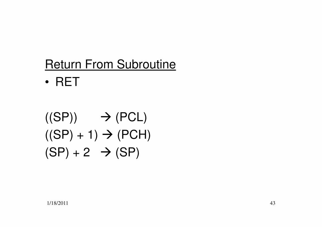
Return From Subroutine
• RET
((SP)) � (PCL)
1/18/2011 43
((SP)) � (PCL)
((SP) + 1) � (PCH)
(SP) + 2 � (SP)
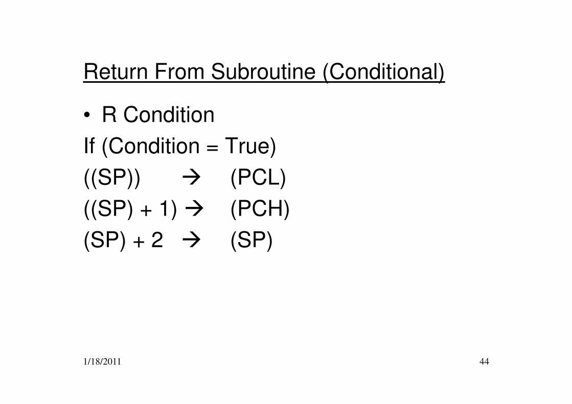
Return From Subroutine (Conditional)
• R Condition
If (Condition = True)
((SP)) � (PCL)
((SP) + 1) � (PCH)
1/18/2011 44
((SP) + 1) � (PCH)
(SP) + 2 � (SP)
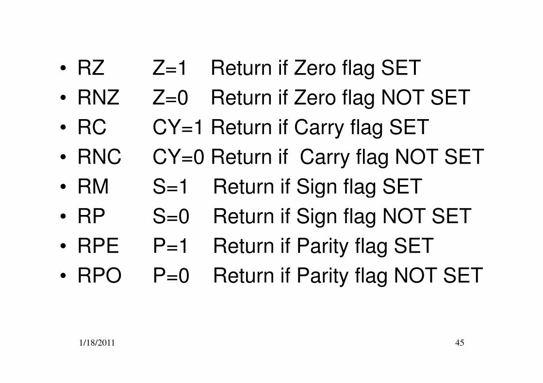
• RZ Z=1 Return if Zero flag SET
• RNZ Z=0 Return if Zero flag NOT SET
• RC CY=1 Return if Carry flag SET
• RNC CY=0 Return if Carry flag NOT SET
• RM S=1 Return if Sign flag SET
1/18/2011 45
• RM S=1 Return if Sign flag SET
• RP S=0 Return if Sign flag NOT SET
• RPE P=1 Return if Parity flag SET
• RPO P=0 Return if Parity flag NOT SET
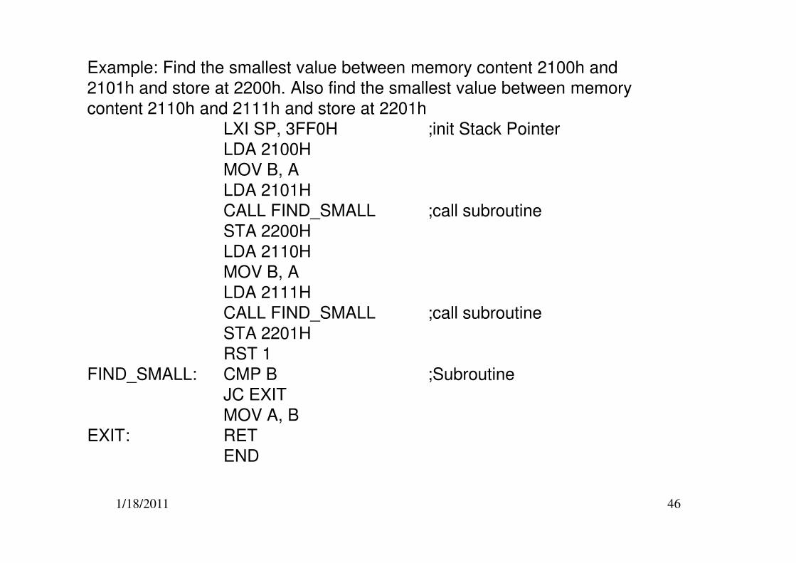
Example: Find the smallest value between memory content 2100h and
2101h and store at 2200h. Also find the smallest value between memory
content 2110h and 2111h and store at 2201h
LXI SP, 3FF0H ;init Stack Pointer
LDA 2100H
MOV B, A
LDA 2101H
CALL FIND_SMALL ;call subroutine
STA 2200H
LDA 2110H
MOV B, A
1/18/2011 46
LDA 2111H
CALL FIND_SMALL ;call subroutine
STA 2201H
RST 1
FIND_SMALL: CMP B ;Subroutine
JC EXIT
MOV A, B
EXIT: RET
END
I/O,Stack, Machine Control
Instruction
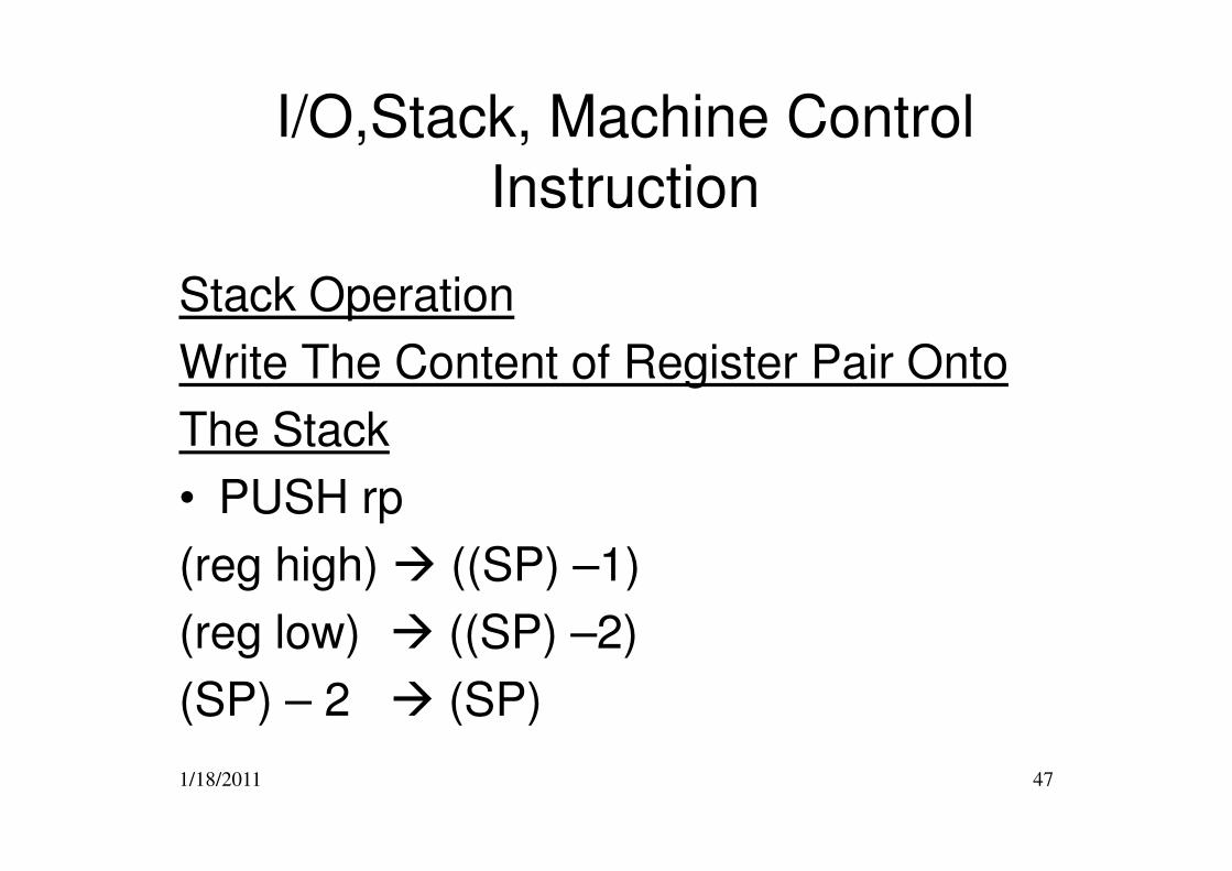
Stack Operation
Write The Content of Register Pair Onto
The Stack
1/18/2011 47
The Stack
• PUSH rp
(reg high) � ((SP) –1)
(reg low) � ((SP) –2)
(SP) – 2 � (SP)
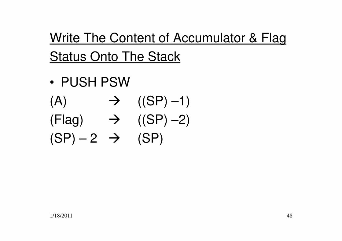
Write The Content of Accumulator & Flag
Status Onto The Stack
• PUSH PSW
(A) � ((SP) –1)
(Flag) � ((SP) –2)
1/18/2011 48
(Flag) � ((SP) –2)
(SP) – 2 � (SP)
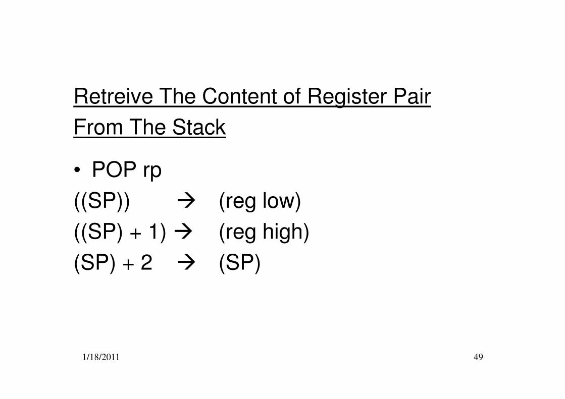
Retreive The Content of Register Pair
From The Stack
• POP rp
((SP)) � (reg low)
1/18/2011 49
((SP)) � (reg low)
((SP) + 1) � (reg high)
(SP) + 2 � (SP)
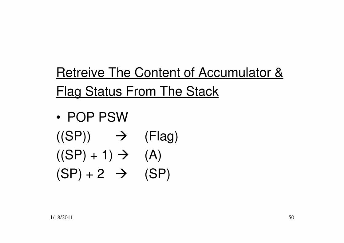
Retreive The Content of Accumulator &
Flag Status From The Stack
• POP PSW
1/18/2011 50
• POP PSW
((SP)) � (Flag)
((SP) + 1) � (A)
(SP) + 2 � (SP)
STACK OPERATION
Lecture 2
(Revision)
1/18/2011 51
(Revision)
How the Stack Works
• The stack is a reserved area of memory. It operates as a last-in first-out bank of registers.
• The memory locations, which constitute the stack, are used to store binary information temporarily during program execution.
• The stack can be located anywhere in read/write memory, but is
1/18/2011 52
• The stack can be located anywhere in read/write memory, but is usually defined such that it neither interferes with the program memory space or the data memory space.
• The start address of the stack is specified at the initialisation stage of the program by loading the 16-bit CPU register, called the stack pointer, with the desired address of the start of the stack.
– e.g LXI SP, data 16
How the Stack Works
• Data from CPU register pairs are stored in the stack area of memory when the processor executes a push rp instruction.
• The contents of the program counter is automatically stored in the stack area of memory whenever the processor executes a call or restart (rst n) instruction.
1/18/2011 53
call or restart (rst n) instruction.
• Data stored in the stack area of memory are returned to processor register pairs when the processor executes a pop rpinstruction.
• Data is automatically transferred from the stack area of memory to the program counter whenever the processor executes a return (ret) instruction.
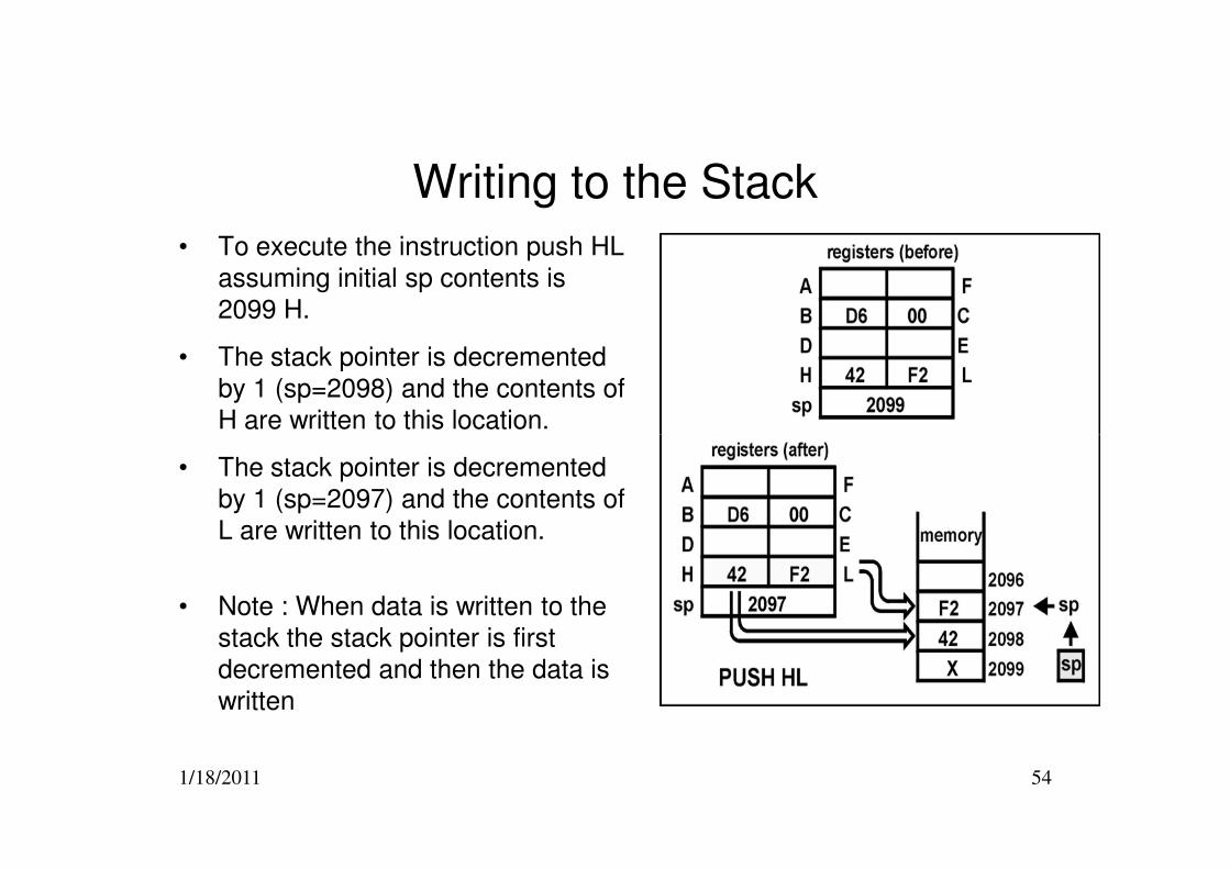
Writing to the Stack
• To execute the instruction push HL
assuming initial sp contents is
2099 H.
• The stack pointer is decremented
by 1 (sp=2098) and the contents of
H are written to this location.
1/18/2011 54
• The stack pointer is decremented
by 1 (sp=2097) and the contents of
L are written to this location.
• Note : When data is written to the
stack the stack pointer is first
decremented and then the data is
written
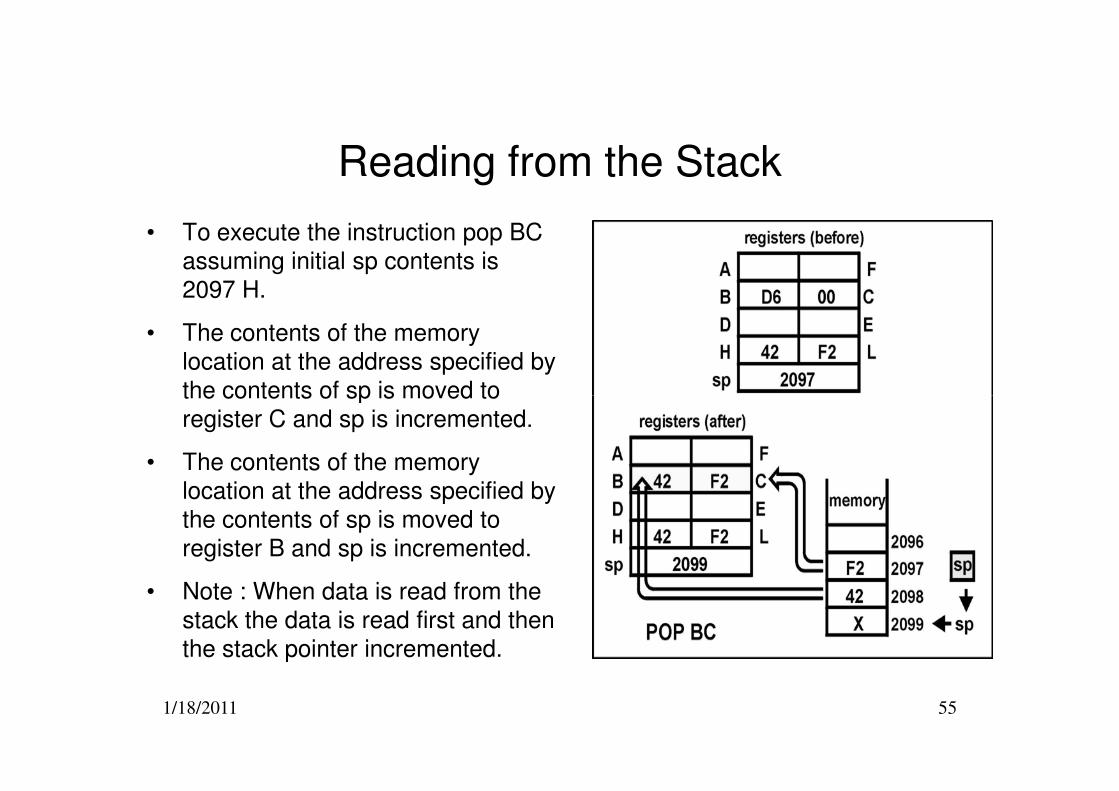
Reading from the Stack
• To execute the instruction pop BC
assuming initial sp contents is
2097 H.
• The contents of the memory
location at the address specified by
the contents of sp is moved to
1/18/2011 55
the contents of sp is moved to
register C and sp is incremented.
• The contents of the memory
location at the address specified by
the contents of sp is moved to
register B and sp is incremented.
• Note : When data is read from the
stack the data is read first and then
the stack pointer incremented.
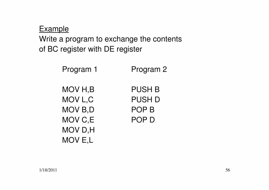
Example
Write a program to exchange the contents
of BC register with DE register
Program 1 Program 2
MOV H,B PUSH B
1/18/2011 56
MOV L,C PUSH D
MOV B,D POP B
MOV C,E POP D
MOV D,H
MOV E,L
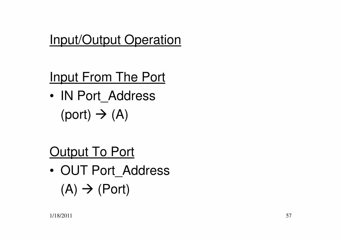
Input/Output Operation
Input From The Port
• IN Port_Address
(port) � (A)
1/18/2011 57
(port) � (A)
Output To Port
• OUT Port_Address
(A) � (Port)
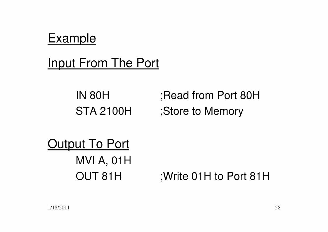
Example
Input From The Port
IN 80H ;Read from Port 80H
STA 2100H ;Store to Memory
1/18/2011 58
STA 2100H ;Store to Memory
Output To Port
MVI A, 01H
OUT 81H ;Write 01H to Port 81H
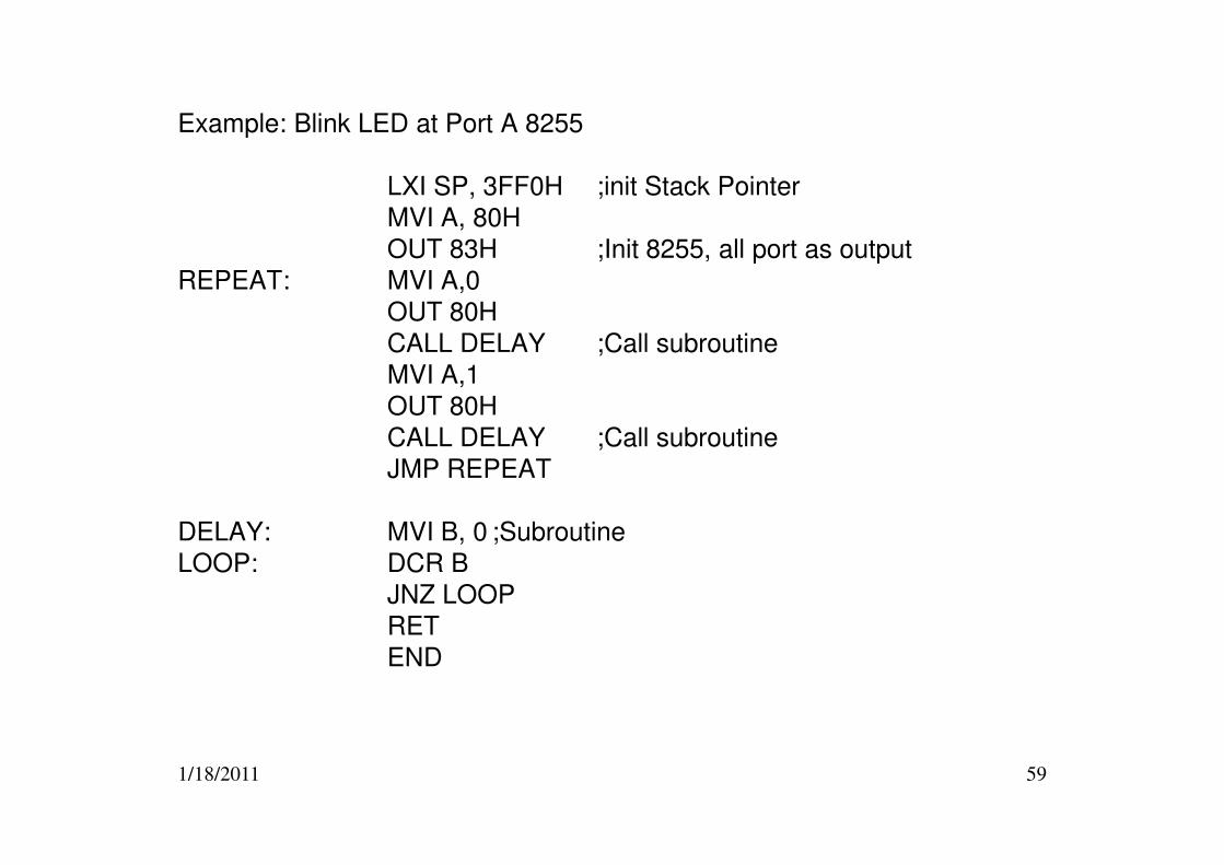
Example: Blink LED at Port A 8255
LXI SP, 3FF0H ;init Stack Pointer
MVI A, 80H
OUT 83H ;Init 8255, all port as output
REPEAT: MVI A,0
OUT 80H
CALL DELAY ;Call subroutine
MVI A,1
OUT 80H
CALL DELAY ;Call subroutine
1/18/2011 59
CALL DELAY ;Call subroutine
JMP REPEAT
DELAY: MVI B, 0 ;Subroutine
LOOP: DCR B
JNZ LOOP
RET
END
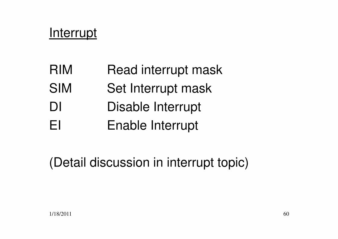
Interrupt
RIM Read interrupt mask
SIM Set Interrupt mask
DI Disable Interrupt
EI Enable Interrupt
1/18/2011 60
EI Enable Interrupt
(Detail discussion in interrupt topic)
NEXT WEEK
ASSEMBLY LANGUAGE PROGRAMMING
1/18/2011 61
PROGRAMMING