introduction to. a metallic apparatus for sending and receiving electromagnetic waves. a usually...
TRANSCRIPT

INTRODUCTION
TO

• A metallic apparatus for sending and receiving electromagnetic waves.
• A usually metallic device (as a rod or wire) for radiating or receiving radio waves.
• A transitional structure between free-space and a guiding structure.
What is an antenna?

Prominent Definition Of an Antenna
The antenna can be defined as,
“A truncated transmission line with output impedance equal to the impedance of the
free space i.e. 377 Ω”
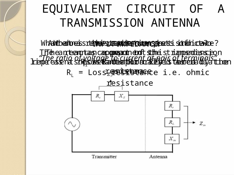
EQUIVALENT CIRCUIT OF A TRANSMISSION ANTENNA
INPUT IMPEDANCE:
“The ratio of voltage to current at pair of terminals”
Antenna resistance consists of two components: Rr = Radiation Resistance
RL = Loss resistance i.e. ohmic resistance
What is the radiation resistance?The antennas appear to the transmission line as a
resistance Rr called as radiation resistance.
What does the reactance part indicate?The reactance part of this impedance represents power
temporarily stored by the antenna.

MAJOR TYPES OF ANTENNAE
• Wire antennas
• Aperture antennas
• Reflector antennas
• Patch antennas
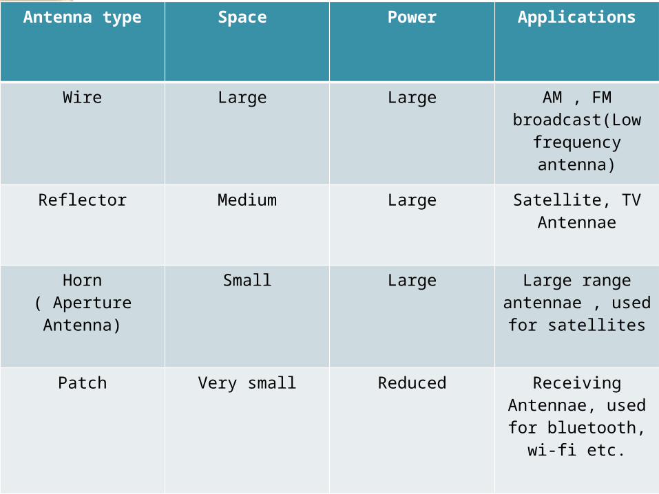
Antenna type Space Power Applications
Wire Large Large AM , FM broadcast(Low
frequency antenna)
Reflector Medium Large Satellite, TV Antennae
Horn( Aperture Antenna)
Small Large Large range antennae , used
for satellites
Patch Very small Reduced Receiving Antennae, used
for bluetooth, wi-fi etc.
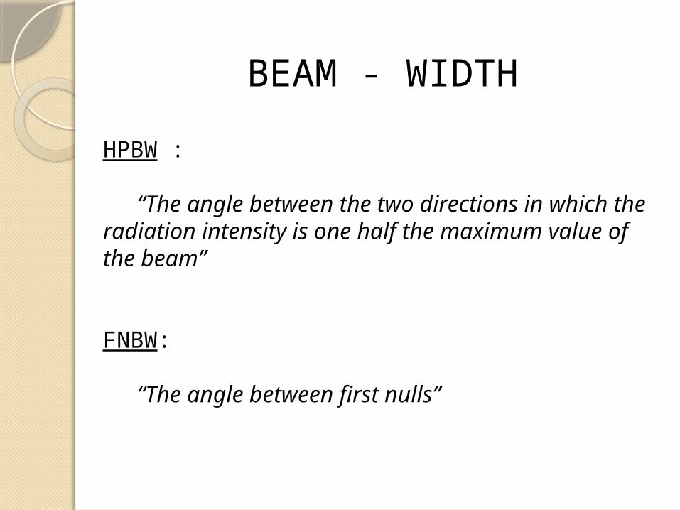
BEAM - WIDTH
HPBW :
“The angle between the two directions in which the radiation intensity is one half the maximum value of the beam”
FNBW:
“The angle between first nulls”
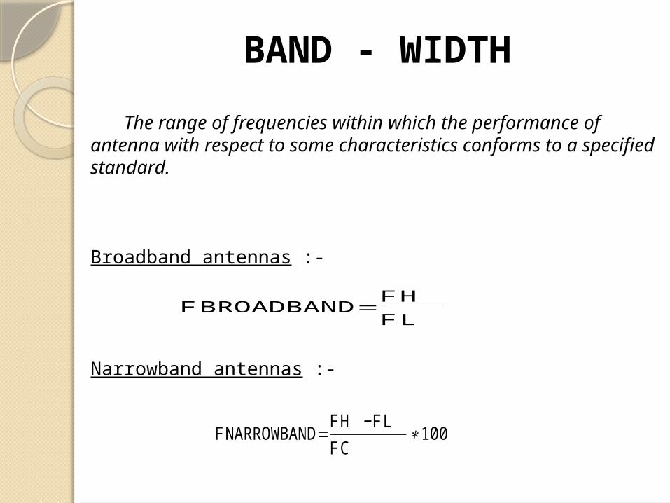
BAND - WIDTH
The range of frequencies within which the performance of antenna with respect to some characteristics conforms to a specified standard.
Broadband antennas :-
Narrowband antennas :-
F BROADBAND=F H F L
F NARROWBAND=F H −F L FC
∗100
Polarisation
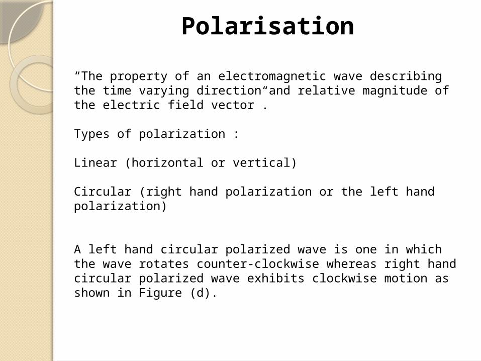
“The property of an electromagnetic wave describing the time varying direction and relative magnitude of the electric field vector”.
Types of polarization : Linear (horizontal or vertical)
Circular (right hand polarization or the left hand polarization)
A left hand circular polarized wave is one in which the wave rotates counter-clockwise whereas right hand circular polarized wave exhibits clockwise motion as shown in Figure (d).

Linearly polarized waveIf the path of the electric field vector is back and forth along a
line, it is said to be linearly polarized.
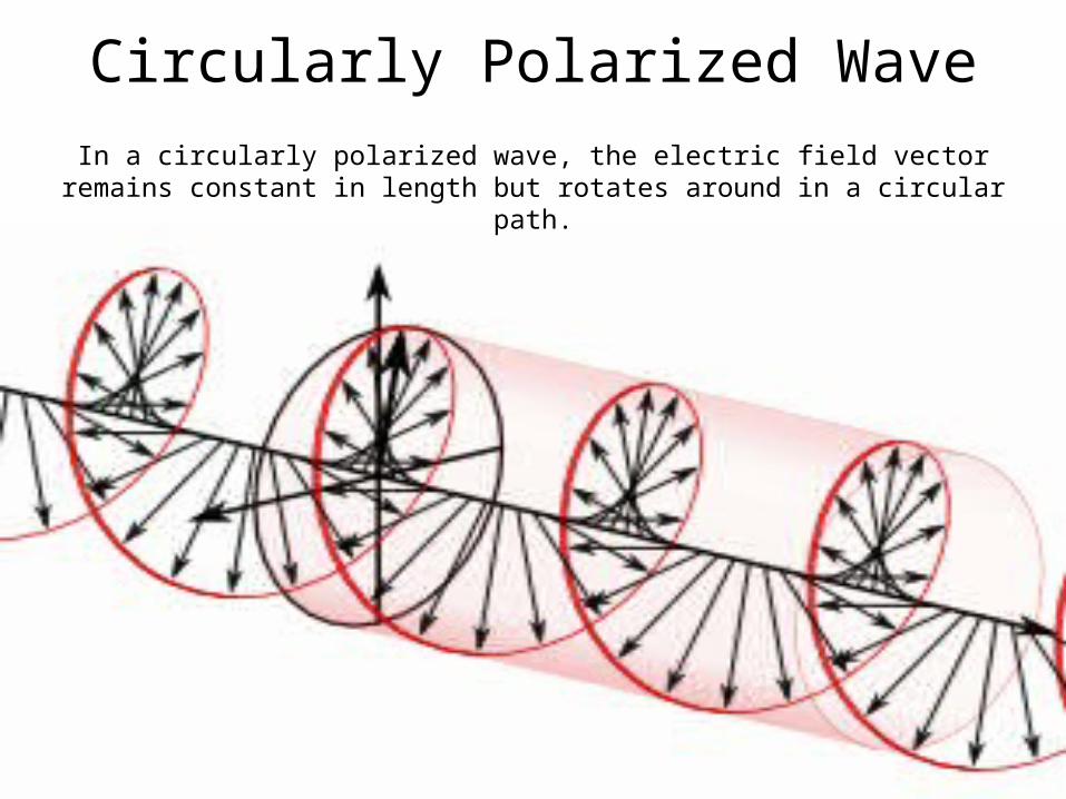
Circularly Polarized WaveIn a circularly polarized wave, the electric field vector remains constant in length but
rotates around in a circular path.

Antenna aperture
The area or part of the antenna which extracts power from the wave, that is, which actually comes in contact of EMW falling on it.
The total power is extracted from a passing wave being proportional to the aperture or area of its mouth.
Antenna efficiency :
Eap =

Directivity“ The property of radiating more strongly in some directions than in
others is called the directivity of the antenna”
It can also be called as the ratio of the maximum power density to its average value over a sphere as observed in the far field of an antenna.
where,U is the radiation intensity of the antenna;
UI is the radiation intensity of an isotropic source;
P is the total power radiated.
DIRECTIVITY =

GAIN
“ The gain of an antenna is an actual or realized quantity which is less than the directivity”
Gain can be measured by comparing the maximum power density of the antenna of known gain.
Thus,
GAIN =
GAIN = 4
Wire Antennae
• Dipole
• Monopole
• Yagi-Uda
• Helix

Hertz antenna or a half-wave dipole antenna :
“An antenna having a physical length that is one-
half wavelength of the applied frequency”
Hertz antennas are not found at frequencies below 2MHz
A Dipole Antenna

17
A Dipole Antenna
Dipole Antenna
The dipole antenna is connected to an alternating AC voltage source which causes current to flow from one side of the antenna to the other.
When the cycle is completed, direction of current reverses.

18
Dipole antenna
ForceField
Imbalance of electrons create a force field i.e. an electromagnetic (EM) wave.
EM wave consists of :
Electric field E(volts/meter),
Magnetic field H (amps/meter).

19
Dipole antenna
ForceField
The E produced by antenna is equal to the ratio of the difference in voltage potential of the legs of the antenna to the distance in meters between the ends.
A displacement current is present along with the E field and is a function of the capacitive reactance between the legs of the antenna.
This displacement current creates an inductive (i.e., magnetic) H field in amps/m which is at right angles to the E field.
20
Dipole antenna
ForceField
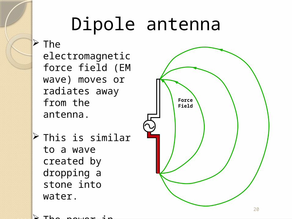
The electromagnetic force field (EM wave) moves or radiates away from the antenna.
This is similar to a wave created by dropping a stone into water.
The power in the field decreases as the square of the distance from the antenna.
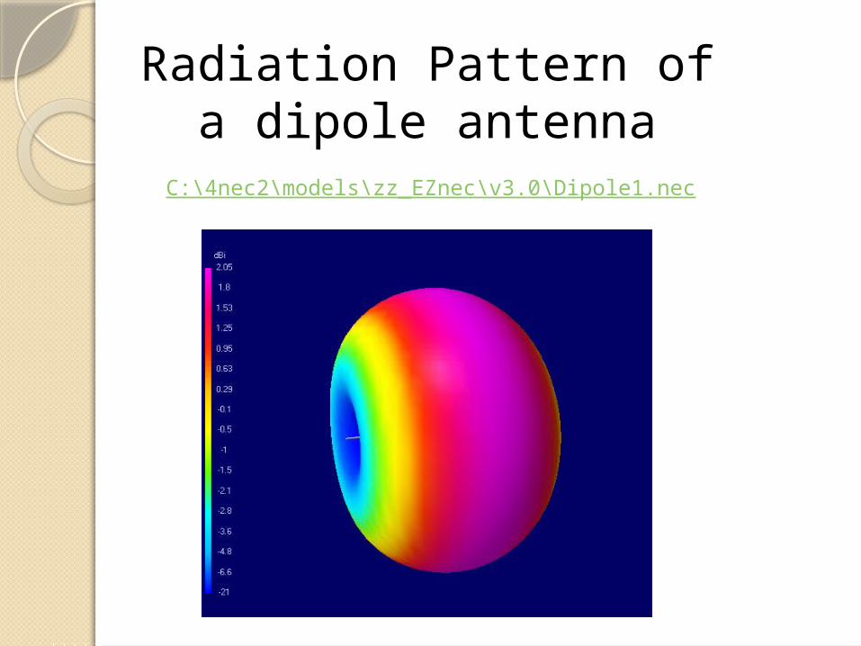
Radiation Pattern of a dipole antenna
C:\4nec2\models\zz_EZnec\v3.0\Dipole1.nec
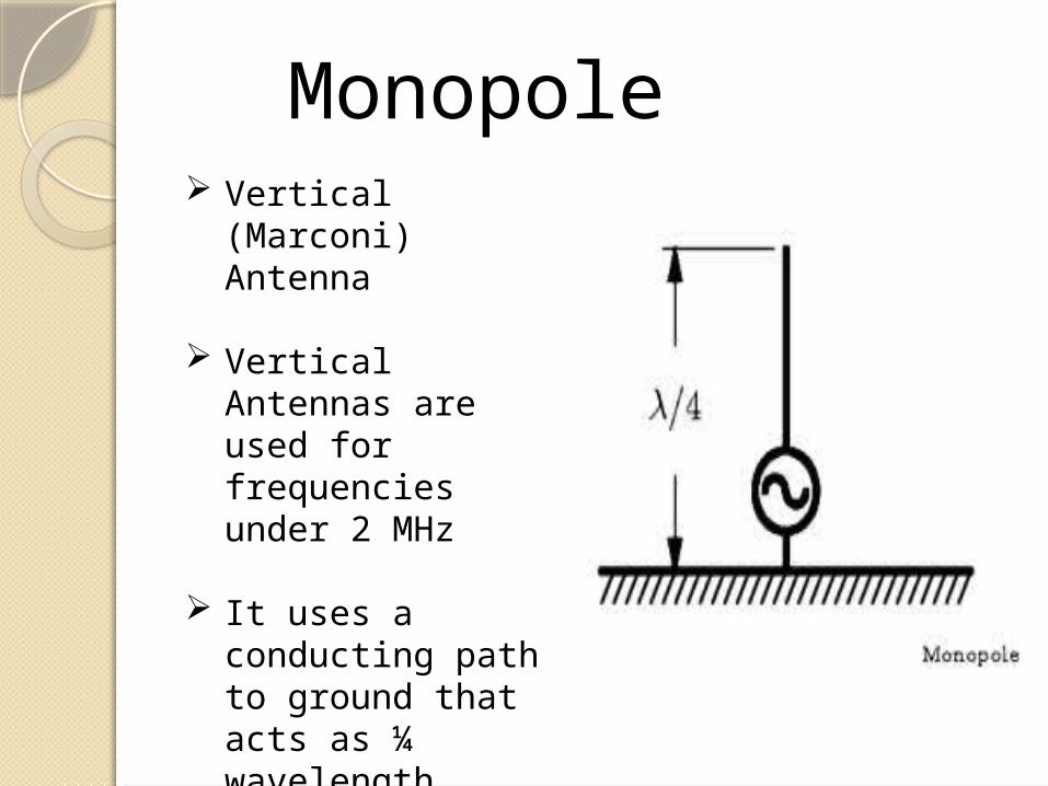
Monopole Vertical (Marconi)
Antenna
Vertical Antennas are used for frequencies under 2 MHz
It uses a conducting path to ground that acts as ¼ wavelength portion the antenna above the ground.

Evolution of monopole from dipole

Working of a monopole antenna
A monopole antenna is a type of radio antenna formed by replacing one half of a dipole antenna with a ground plane at right-angles to the remaining half.
If the ground plane is large enough, the monopole behaves like a dipole, as if its reflection in the ground plane formed the missing half of the dipole

Radiation Pattern of Monopole
C:\4nec2\models\HFsimple\_new.nec


Limitations of monopoles
Needs perfect ground.
Doesn’t work satisfactorily in bad weather conditions .
Doesn’t have large range.
Operate satisfactorily for low frequencies only.

Yagi – Uda Antenna

The Yagi-Uda Antenna is a “Directional antenna”
Invented by,
1) Dr.Hidetsugu Yagi [Tohoku Imperial University ]
2)Dr. Shintaro Uda.
Yagi-Uda Antenna

Antenna Principles
Direct signal in one direction
Only the driving element is connected directly to the feeder
The other elements couple to the transmitter power through the local electromagnetic fields which induce currents in them.

How does a Yagi - Uda antenna work ?
A Yagi-Uda antenna is a linear array of parallel dipoles.
Yagi unit consists of , 1. Driver or driven element, 2. Reflector, 3. Director.
Driven element (Dipole or Folded dipole) is energized with transmission line.
Parasite elements excite from near field coupling by the driven element.

Gain is related to boom length and number of directors.
Typical Gain : 5 to 15 dB (Addition of directors up to 5 or 6 provides significant increase in gain. )
Stacking (Horizontal or vertical) : To increase gain
Polarization : Linear (Horizontal or Vertical)
Yagi specifications

Radiation Pattern of Yagi - UdaD:\College Sat\College Sat\Antennas Section\YagiS
\144-5Yagi.nec

Advantages Highly Directional antenna.
Simple to build.
Low cost.
Light Weight.
High gain.
Less critical tuning.
Wider bandwidth .
Disadvantage The Yagi Antenna design is obtrusive.

Applications :
Television antenna set.
Amateur radio operators (HAMS) for communication.
On frequencies from short wave, through VHF/UHF and microwaves band.
Satellite Tracking.
Radar.
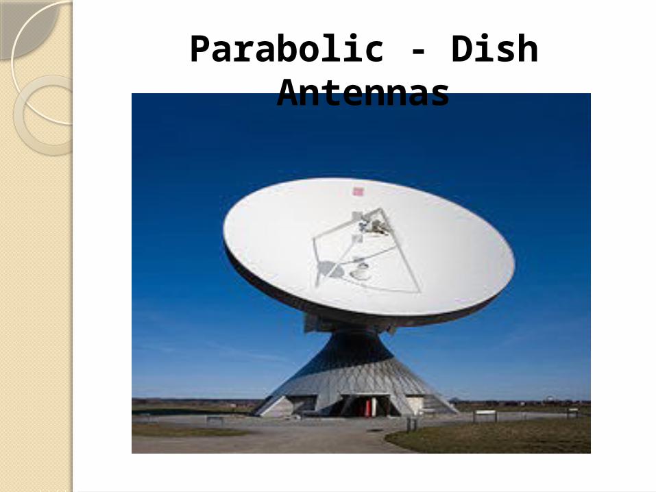
Parabolic - Dish Antennas
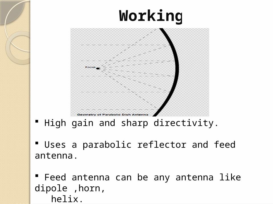
Working
High gain and sharp directivity.
Uses a parabolic reflector and feed antenna.
Feed antenna can be any antenna like dipole ,horn, helix.
Reflector provides high gain because like mirror of reflecting telescope.
Parabolic dish antennas are not used at lower frequencies such as VHF region because size of dish will be very large.
Gain can be limited by size of the reflector.
Polarization : Takes polarization of feed antenna.
Typical gain : 20 dB to 30 dB.

40
Methods of feeding parabolic reflectors
Dual offsetFront – fed reflectors Offset reflectors Cassegrain fed

Advantages Highly Directional.
High gain.
Disadvantages Can not be used at VHF frequency.
Less accuracy , sometimes parabolic surfaces are rough.
Use other antenna as feed.
Highly expensive.
Applications
Radio , satellite T.V broadcasting.
Data communication.
Radar in UHF and SHF bands.
Earlier applications included ground-based and airborne radar and radio astronomy.


This is the biggest antenna in the world
It is built into the mountain side of Arecibo Puerto Rico.
The feed antenna is suspended by steel cables strung from 300-feet towers, an array of antennas hangs above an aluminum bowl 1,000 feet in diameter that gazes into space.
This antenna is actually the most accurate
meteorite detection system known to man.
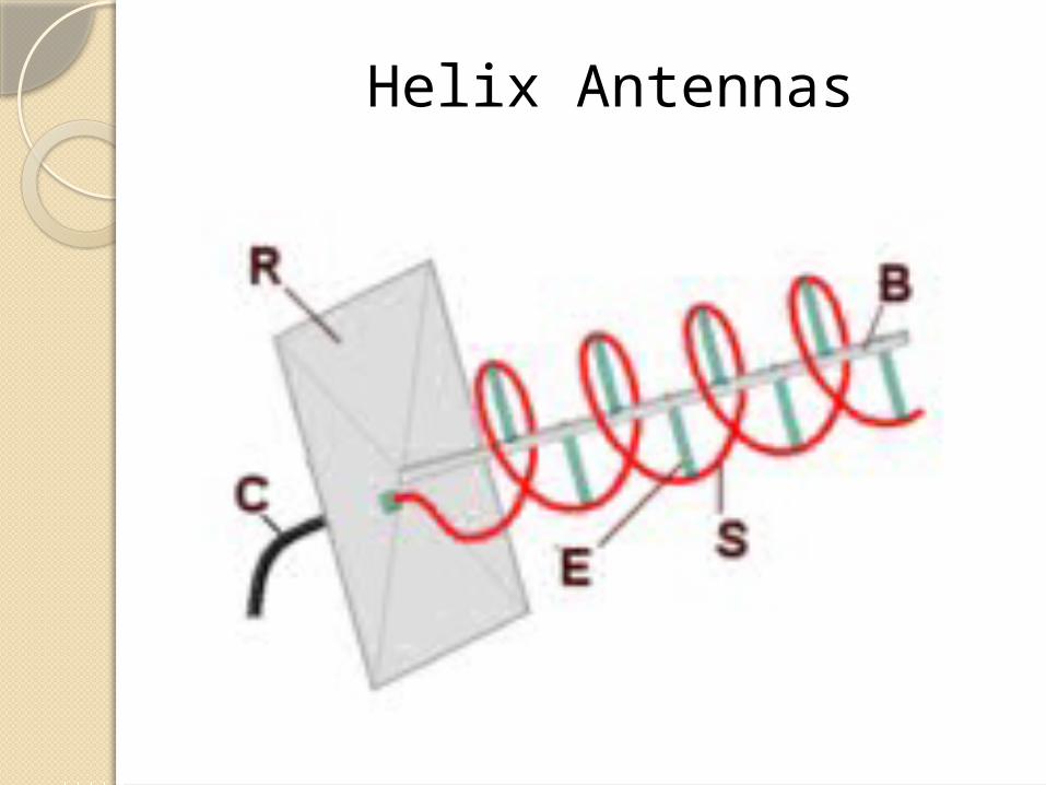
Helix Antennas

Helix Antenna
Wire is wounded in the form of HELIX.
Helix is broadband UHF and VHF antenna to provide circular polarization.
Fed by co-axial cable.

Working Operates in two modes :
1) Normal (Broadside),
2) Axial (End-Fire).
Helix antenna mounted over Ground plane which makes radiation unidirectional.

Normal Mode
Radiation is max. in direction perpendicular to axis of helix.
Polarization : nearly circular .
Dimension of helix are very small compared to wavelength.
Narrow B/W and low radiation efficiency.
Not used practically.

Radiation is max. in direction along axis of helix.
It is circularly polarized i.e receives signals with arbitrary polarization.
Typical gain : 10 dB.
Polarization : Circular
Frequency limit : VHF and UHF.
Axial Mode
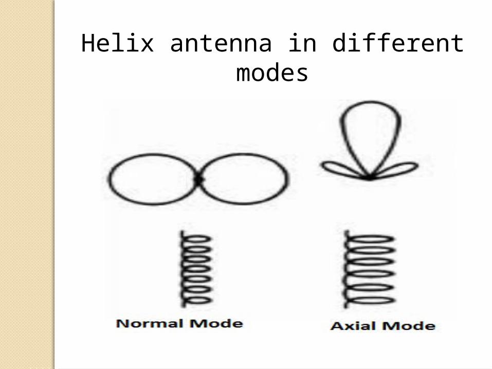
Helix antenna in different modes

D:\College Sat\College Sat\Antennas Section\YagiS\helix.nec
Radiation Pattern of Helix antenna in Axial mode

Advantages : (Axial mode) Wide Bandwidth.
Circular polarization.
Highest Directivity.
High Radiation efficiency.
Disadvantages Very Expensive
Hard to Construct.

Application
Handheld satellite communication device such as radios, mobile.
Global positioning system.
For tracking in satellite communication.

THANK YOU!!!