introduction to 3d graphics (part 3) · introduction to 3d graphics (part 3) john k. bennett iwks...
TRANSCRIPT

Introduction to 3D Graphics(Part 3)
John K. Bennett
IWKS 3400/5400 – CSCI 2940
Spring 2019Note: There is a bit of math in this lecture, but you can use the techniques described without complete mastery the math.

Lighting Models
• Want to simulate ‘real-world’ lighting• Want to compute lighting fast (i.e., in real-time)• Need to model: Different kinds of light sources: Sun, Fire,
Light-bulbs, ... Different types of materials: dull, shiny, ... Different light source colors Different material colors
...Put all of these together to get a lighting model

Light Sources

Light Intensity And Color
Intensity or brightness of lightFor uncolored light, it’s a numerical value in [0,1]
• 0 = no light• 1 = maximum brightness
Color of light is an RGB (Red-Green-Blue) value3 intensity values between 0 and 1,
e.g., {0.5, 0.4, 0.2}
Lighting Components
• Diffuse
• Ambient
• Specular
• Emissive
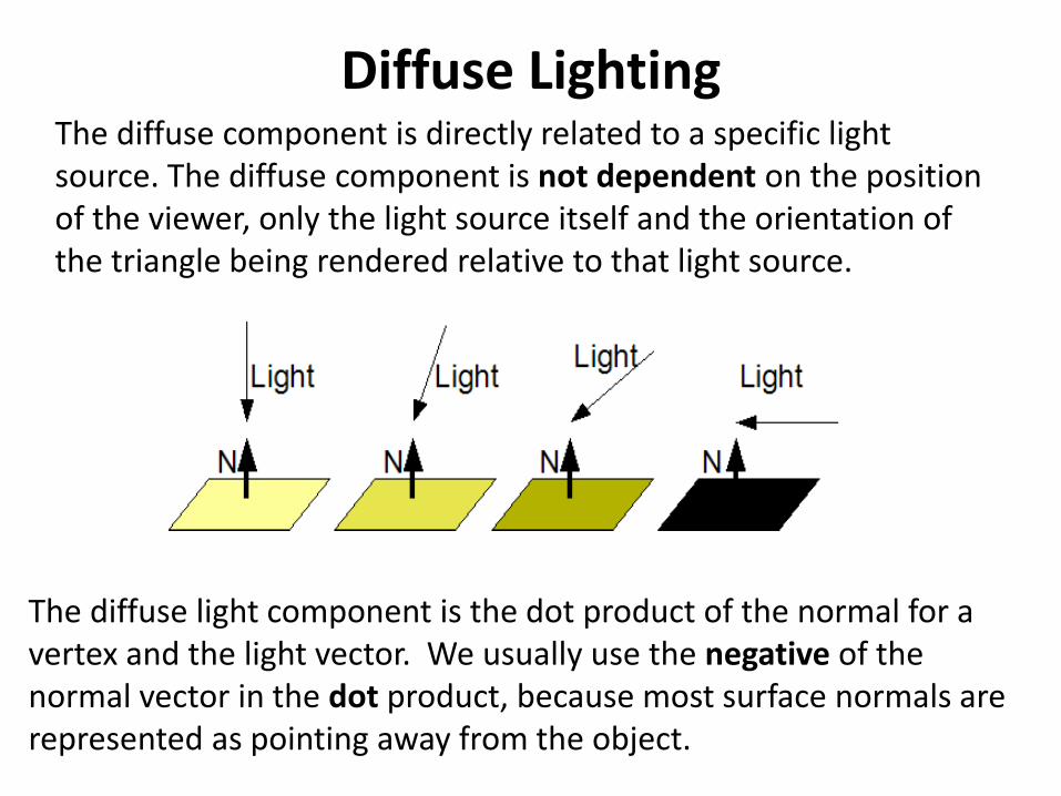
Diffuse LightingThe diffuse component is directly related to a specific light source. The diffuse component is not dependent on the position of the viewer, only the light source itself and the orientation of the triangle being rendered relative to that light source.
The diffuse light component is the dot product of the normal for a vertex and the light vector. We usually use the negative of the normal vector in the dot product, because most surface normals are represented as pointing away from the object.

Dot ProductA ● B = |A| x |B| x cos θwhere |A| = length of Vector AIf |A| and |B| both = 1, A ● B = cos θ

Diffuse Lighting
Lambert’s Law: For surfaces that are ideally diffuse, i.e. noshininess, the intensity or brightness of reflected light is,
= normal, = light vector, θ = angle between and
= ● = cos θ

Calculating Diffuse Lighting1. Determine the direction of the light relative to the pixel:
float3 LightDir = normalize(PixelPos3D – LightPos3D);
2. Compute the diffuse lighting effect:
diffuseLight = dot(-LightDir, normalize(PixelNormalVector));
3. Map result to[0,1] range:
diffuseLight = saturate(diffuseLight);
4. Incorporate a lighting strength factor:
diffuseLight *= xLightPower;
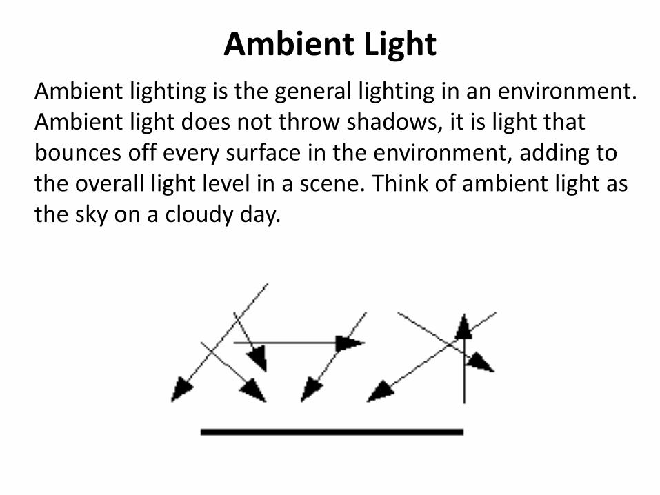
Ambient LightAmbient lighting is the general lighting in an environment. Ambient light does not throw shadows, it is light that bounces off every surface in the environment, adding to the overall light level in a scene. Think of ambient light as the sky on a cloudy day.
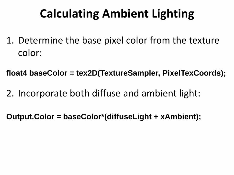
Calculating Ambient Lighting
1. Determine the base pixel color from the texture color:
float4 baseColor = tex2D(TextureSampler, PixelTexCoords);
2. Incorporate both diffuse and ambient light:
Output.Color = baseColor*(diffuseLight + xAmbient);

Specular LightingSpecular lighting effects occur where the object reflects the light source towards the eyes of the viewer. The difference between specular lighting and diffuse lighting is that the position of the viewer is important when calculating specular lighting. To compute specular highlights, we mirror the direction of the light (L) over the normal (N) of the pixel in question, and compare this vector to the eye vector (R). If both are almost the same, the pixel is situated in a specular highlighted area.

Calculating Specular Lighting1. Use the HLSL reflect intrinsic function to get R by calculating the
direction of the light, reflected over the normal vector:
float3 reflectionVector = -reflect(LightDirection, normalVector);
2. Determine how nearly this reflected vector is the same as the eyeVector by taking their dot product (the dot product will be 1 if they are equal, and 0 if they are perpendicular):
float specular = abs(dot(normalize(reflectionVector), normalize(eyeVector)));
3. Only consider specular values that are higher than ~ 0.95. By taking the specular to a very high power, only those numbers very close to 1 will remain (consider: 1256 = 1; but 0.9256 = 1.93233498 × 10⁻¹²).
specular = pow(specular, 256);
Power : 1, 10, 50
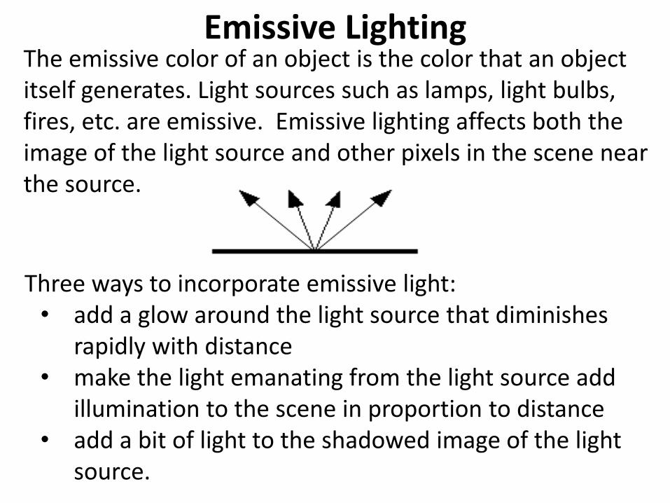
Emissive LightingThe emissive color of an object is the color that an object itself generates. Light sources such as lamps, light bulbs, fires, etc. are emissive. Emissive lighting affects both the image of the light source and other pixels in the scene near the source.
Three ways to incorporate emissive light: • add a glow around the light source that diminishes
rapidly with distance• make the light emanating from the light source add
illumination to the scene in proportion to distance• add a bit of light to the shadowed image of the light
source.
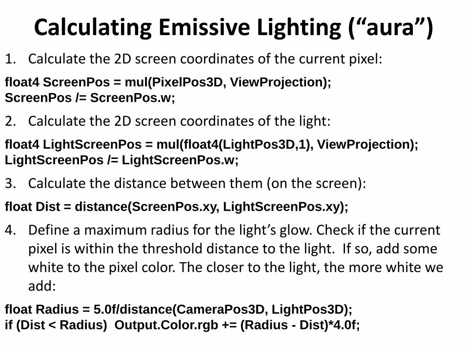
Calculating Emissive Lighting (“aura”)1. Calculate the 2D screen coordinates of the current pixel:
float4 ScreenPos = mul(PixelPos3D, ViewProjection);
ScreenPos /= ScreenPos.w;
2. Calculate the 2D screen coordinates of the light:
float4 LightScreenPos = mul(float4(LightPos3D,1), ViewProjection);
LightScreenPos /= LightScreenPos.w;
3. Calculate the distance between them (on the screen):
float Dist = distance(ScreenPos.xy, LightScreenPos.xy);
4. Define a maximum radius for the light’s glow. Check if the current pixel is within the threshold distance to the light. If so, add some white to the pixel color. The closer to the light, the more white we add:
float Radius = 5.0f/distance(CameraPos3D, LightPos3D);
if (Dist < Radius) Output.Color.rgb += (Radius - Dist)*4.0f;
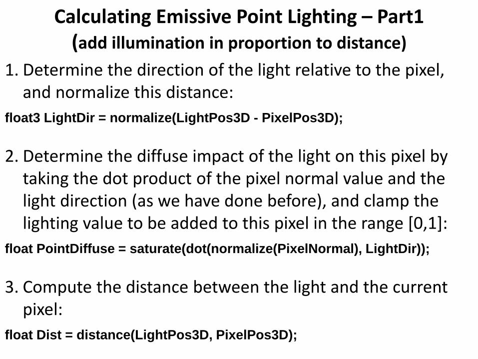
Calculating Emissive Point Lighting – Part1(add illumination in proportion to distance)
1. Determine the direction of the light relative to the pixel, and normalize this distance:
float3 LightDir = normalize(LightPos3D - PixelPos3D);
2. Determine the diffuse impact of the light on this pixel by taking the dot product of the pixel normal value and the light direction (as we have done before), and clamp the lighting value to be added to this pixel in the range [0,1]:
float PointDiffuse = saturate(dot(normalize(PixelNormal), LightDir));
3. Compute the distance between the light and the current pixel:
float Dist = distance(LightPos3D, PixelPos3D);

Calculating Emissive Point Lighting – Part2(add illumination in proportion to distance)
4. Compute the rate at which each light will fall off with respect to distance using the formula:
Katt = 1 - (d/a)f
Katt is the brightness factor to apply to current pixeld is the distance between the pixel and the light sourcea is the distance at which the light should stop affecting objectsf is the falloff exponent that determines the shape of the exponential falloff curve.
float Att = 1 - pow(clamp((Dist / a), 0, 1), f);
5. Add the diffuse and attenuation factors for the light to the scene.
Output.Color += (PointDiffuse * Att);
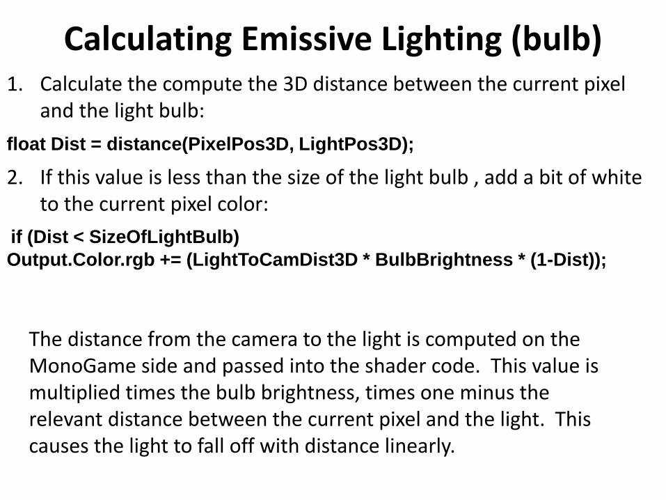
Calculating Emissive Lighting (bulb)1. Calculate the compute the 3D distance between the current pixel
and the light bulb:
float Dist = distance(PixelPos3D, LightPos3D);
2. If this value is less than the size of the light bulb , add a bit of white to the current pixel color:
if (Dist < SizeOfLightBulb)
Output.Color.rgb += (LightToCamDist3D * BulbBrightness * (1-Dist));
The distance from the camera to the light is computed on the MonoGame side and passed into the shader code. This value is multiplied times the bulb brightness, times one minus the relevant distance between the current pixel and the light. This causes the light to fall off with distance linearly.

Putting It All Together
Total intensity (color) at any point
Remember, it is an approximation to the real-worldOther models exist!

Where to Calculate: VS vs. PS?
Where do we evaluate the lighting equation?
Cheap approach: Evaluate on every vertex of the mesh. Interpolate the rest of the triangle.
More accurate approach: Per-pixel lighting

Pixel Shader Interpolation
If the vertex density is too small, this technique will create visible artifacts, and the vertex lighting technique will accentuate rather then hide the edges in the 3D model :

Interpolation – Gouraud Shading
First, evaluate lighting RGB value at each vertex

Interpolative or Incremental Shading

Interpolation – Phong Shading
First, interpolate normals
Then, evaluate lighting equation at each point usinginterpolated normal:More accurate and avoids artifacts
(weighted by the length of the normal vectors)

Phong Shading

SHADERS
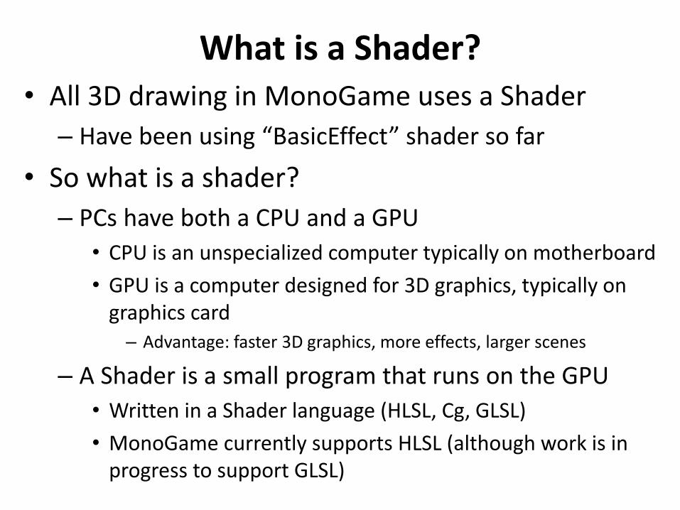
What is a Shader?• All 3D drawing in MonoGame uses a Shader
– Have been using “BasicEffect” shader so far
• So what is a shader?
– PCs have both a CPU and a GPU
• CPU is an unspecialized computer typically on motherboard
• GPU is a computer designed for 3D graphics, typically on graphics card
– Advantage: faster 3D graphics, more effects, larger scenes
– A Shader is a small program that runs on the GPU
• Written in a Shader language (HLSL, Cg, GLSL)
• MonoGame currently supports HLSL (although work is in progress to support GLSL)

Shader Languages• Currently 3 major
shader languages– Cg (Nvidia)
– HLSL (Microsoft)
• Derived from Cg
– GLSL (OpenGL)
• Main influences are – C language
– pre-existing Shader languages developed in university and industry
– All shader languages are quite similar
HLSL(Microsoft, 2002)
GLSL (OpenGL ARB, 2003)
ARB Vertex/Fragment (OpenGL ARB, 2002)
Source: http://http.developer.nvidia.com/CgTutorial/cg_tutorial_chapter01.html (Modified with information on HLSL and GLSL)
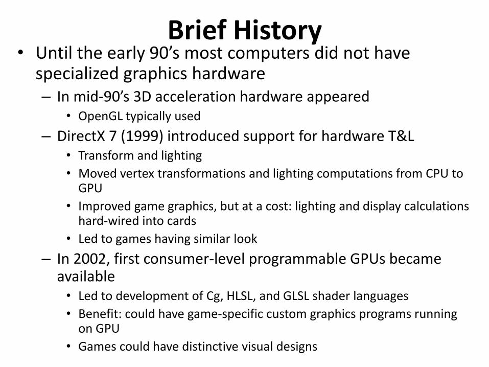
Brief History• Until the early 90’s most computers did not have
specialized graphics hardware– In mid-90’s 3D acceleration hardware appeared
• OpenGL typically used
– DirectX 7 (1999) introduced support for hardware T&L• Transform and lighting
• Moved vertex transformations and lighting computations from CPU to GPU
• Improved game graphics, but at a cost: lighting and display calculations hard-wired into cards
• Led to games having similar look
– In 2002, first consumer-level programmable GPUs became available
• Led to development of Cg, HLSL, and GLSL shader languages
• Benefit: could have game-specific custom graphics programs running on GPU
• Games could have distinctive visual designs

Types of Shaders• Shaders (GPU programs) are specialized into three
(primary) different types:– Vertex Shaders
• Executed once per vertex in a scene.
• Transforms 3D position in space to 2D coordinate on screen
• Can manipulate position, color, texture coordinates
• Cannot add new vertices
– Pixel Shaders (fragment shaders)• Calculates the color of individual pixels
• Used for lighting, texturing, bump mapping, etc.
• Executed once per pixel per geometric primitive
– Geometry Shaders (new in DirectX v10)• Can add/remove vertices from a mesh
• Can procedurally generate geometry, or add detail to shapes
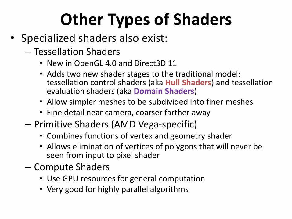
Other Types of Shaders• Specialized shaders also exist:
– Tessellation Shaders• New in OpenGL 4.0 and Direct3D 11 • Adds two new shader stages to the traditional model:
tessellation control shaders (aka Hull Shaders) and tessellation evaluation shaders (aka Domain Shaders)
• Allow simpler meshes to be subdivided into finer meshes• Fine detail near camera, coarser farther away
– Primitive Shaders (AMD Vega-specific)• Combines functions of vertex and geometry shader• Allows elimination of vertices of polygons that will never be
seen from input to pixel shader
– Compute Shaders• Use GPU resources for general computation• Very good for highly parallel algorithms

Shader Basic Control Flow
• C#/MonoGame program sends vertices and textures to the GPU– This “vertex stream” is the
input for the vertex and pixel shader
• Shader executes vertex shader– Once per vertex
• Shader executes pixel shader– Once per pixel in each
primitive object
VertexShader
PixelShader
GPUCPU
C#/MonoGameprogram
vertices, textures
display
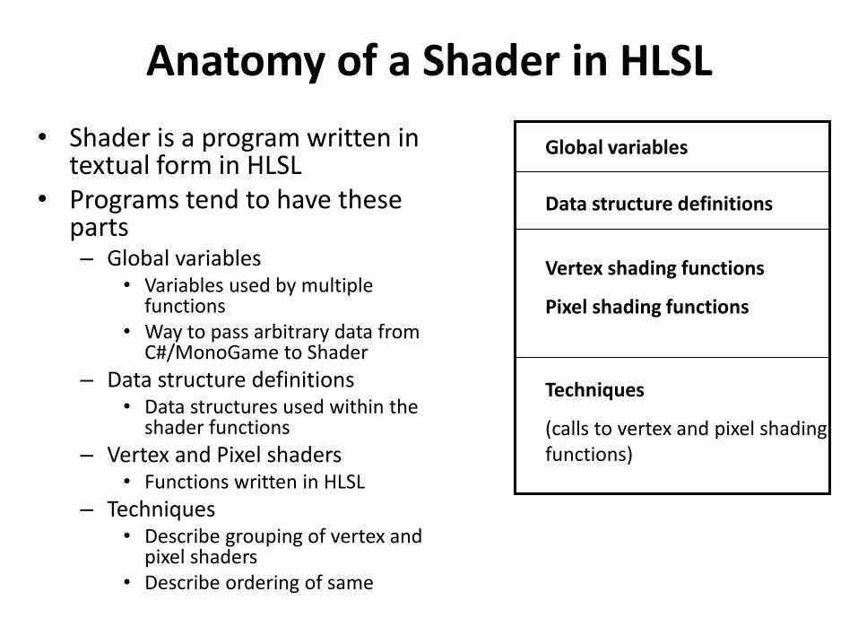
Anatomy of a Shader in HLSL
• Shader is a program written in textual form in HLSL
• Programs tend to have these parts– Global variables
• Variables used by multiple functions
• Way to pass arbitrary data from C#/MonoGame to Shader
– Data structure definitions• Data structures used within the
shader functions
– Vertex and Pixel shaders• Functions written in HLSL
– Techniques• Describe grouping of vertex and
pixel shaders• Describe ordering of same
Global variables
Data structure definitions
Vertex shading functions
Pixel shading functions
Techniques
(calls to vertex and pixel shading functions)
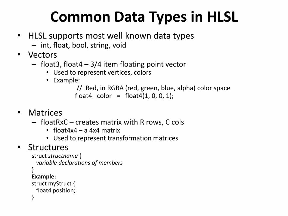
Common Data Types in HLSL• HLSL supports most well known data types
– int, float, bool, string, void
• Vectors– float3, float4 – 3/4 item floating point vector
• Used to represent vertices, colors• Example:
// Red, in RGBA (red, green, blue, alpha) color spacefloat4 color = float4(1, 0, 0, 1);
• Matrices– floatRxC – creates matrix with R rows, C cols
• float4x4 – a 4x4 matrix • Used to represent transformation matrices
• Structuresstruct structname {
variable declarations of members}Example:struct myStruct {
float4 position;}

Passing Information to/from a Shader• There are two ways information is passed into a Shader
1. Directly set global variables
• In C#/MonoGame:
• effect.Parameters[“HLSL_global_variable_name”].SetValue(value)
• Example:
HLSL: float4x4 World; The global variable
C#/MonoGame: effect.Parameters[“World”].SetValue(Matrix.Identity);
2. Semantics
• “Magic” variables
• Names and meaning are hard-wired by HLSL language specification
• Examples:
– POSITION0: a float4 representing the current vertex
» When the HLSL program is executing, before each Vertex shader is called, POSITION0 is updated with the next vertex
– COLOR0: a float4 representing the current pixel color

Example Shader
Example Shader from Chapter 13 of Learning XNA 4.0, Aaron Reed, O’Reilly, 2009.
float4x4 World;
float4x4 View;
float4x4 Projection;
struct VertexShaderInput
{
float4 Position : POSITION0;
};
struct VertexShaderOutput
{
float4 Position : POSITION0;
};
VertexShaderOutput
VertexShaderFunction(VertexShaderInput input) {
VertexShaderOutput output;
float4 worldPosition = mul(input.Position, World);
float4 viewPosition = mul(worldPosition, View);
output.Position = mul(viewPosition, Projection);
return output;
}
Global variables
Data structures
Vertex Shader
Computes final output position (x,y,z,w) from input position
Semantic

Example Shader (cont’d)
Compile Vertex and Pixel
shaders using Shader version 5.0
float4 PixelShaderFunction() : COLOR0
{
return float4(1, 0, 0, 1);
}
Technique Technique1
{
pass Pass1
{
VertexShader = compile vs_5_0
VertexShaderFunction();
PixelShader = compile ps_5_0
PixelShaderFunction();
}
}
Pixel Shader function
Makes every pixel red
Define a technique combining the vertex and pixel shaders
Shader contains a single pass
An output semantic
This is the “technique name”
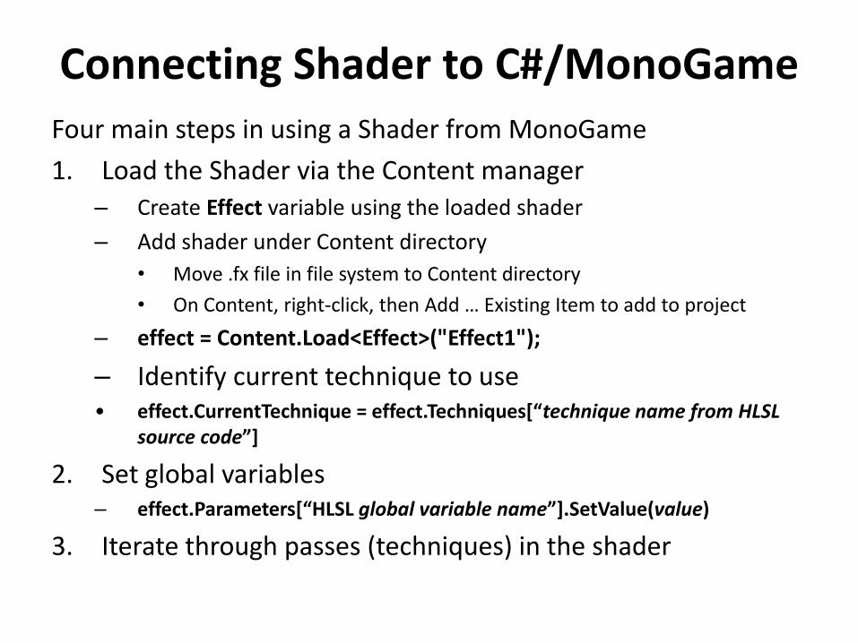
Connecting Shader to C#/MonoGameFour main steps in using a Shader from MonoGame
1. Load the Shader via the Content manager– Create Effect variable using the loaded shader
– Add shader under Content directory
• Move .fx file in file system to Content directory
• On Content, right-click, then Add … Existing Item to add to project
– effect = Content.Load<Effect>("Effect1");
– Identify current technique to use• effect.CurrentTechnique = effect.Techniques[“technique name from HLSL
source code”]
2. Set global variables– effect.Parameters[“HLSL global variable name”].SetValue(value)
3. Iterate through passes (techniques) in the shader

Example: Connecting Shader to C#/MonoGame
Effect effect;
effect = Content.Load<Effect>("Effect1")
effect.CurrentTechnique = effect.Techniques[“Technique1”];
effect.Parameters[“World”].SetValue(Matrix.Identity);
effect.Parameters[“View”].SetValue(camera.view);
effect.Parameters[“Projection”].SetValue(camera.projection);
foreach (EffectPass pass in effect.CurrentTechnique.Passes){
pass.Apply();device.SetVertexBuffer(vertexBuffer);device.DrawPrimitives(PrimitiveType.TriangleStrip, 0, 10);
}
Create effect, load it via Content manager
Set current technique
Set global variables in HLSL code
Iterate through passes inside current technique

Vertex Shader Capabilities
Source: https://en.wikipedia.org/wiki/High-Level_Shading_Language
VS 5.1 = Shader Model 5.1, GCN* 1.0, Fermi**+, Kepler** and Maxwell** 1, DirectX*** 12 (11_0 and 11_1) with WDDM**** 2.0VS 6.0 = Shader Model 6.0, GCN 2.0+ and Maxwell*** 2+, DirectX 12 (12_0 and 12_1) with WDDM 2.1VS 6.1 = Shader Model 6.1, GCN 2.0+ and Maxwell 2+, DirectX 12 (12_0 and 12_1) with WDDM 2.3
* Graphics Core Next (AMD)** Nvidia GPU Microarchitectures*** Microsoft Low-Level Graphics APIs**** MS Windows Display Driver Model (higher level)

Pixel Shader Capabilities
Source: https://en.wikipedia.org/wiki/High-Level_Shading_Language
PS 5.1 = Shader Model 5.1, GCN 1.0 and Fermi+, DirectX 12 (11_0 and 11_1) with WDDM 2.0.PS 6.0 = Shader Model 6.0, GCN 2.0+ and Maxwell 2+, DirectX 12 (12_0 and 12_1) with WDDM 2.1.PS 6.1 = Shader Model 6.1, GCN 2.0+ and Maxwell 2+, DirectX 12 (12_0 and 12_1) with WDDM 2.3.